Robotic Pet Teardown
By Bryan Bergeron
As soon as Christmas passed, I ordered one of the pets for $19 on Amazon — a 50% savings from pre-Christmas prices. The teardown — shown here in Figures 1-8 — was trivial compared to the task of extracting the toy from the theft-proof packaging. It revealed a clean, modular design, relatively well planned circuit board (only two wire jumpers), and excellent attention to the user interface. If you’re interested in peeking inside your own Zhu Zhu, all you’ll need for the operation is a small Phillip’s head screwdriver.
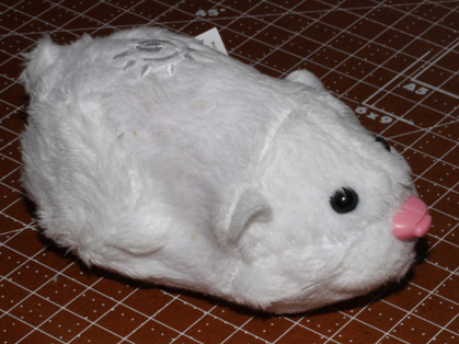
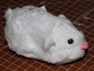
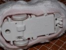
Figure 1 shows the life-sized robot hamster intact and upright. You can just make out the momentary contact button embedded in the nose. The buttons accessed through the head and rear are less obvious. Figure 2 shows the underside of the robot, with the front of the robot to the right. Note the moveable studs to either side of the fixed, center stud on the far right side of the figure. The robot uses these two switches — referred to as data readers by the manufacturer — to detect patterns in the floors of the various Zhu Zhu environments. Depending on the pattern, the robot might move ahead a few inches and then go to sleep, for example.
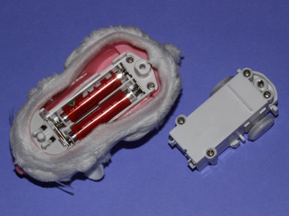
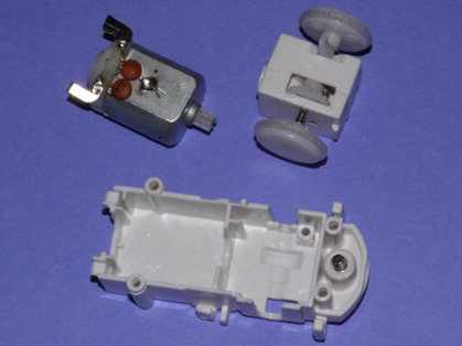
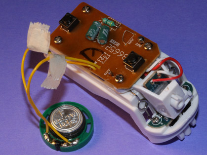
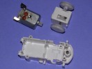
Figure 3 shows the drive module removed from the shell. In this figure, the fur-covered shell is upside down and the nose of the robot is pointing down and left. The rectangular drive module is shown upright, also aligned to the lower left corner of the figure. The components of the drive module — a DC motor and gear box — are shown in Figure 4. The only electrical connection to the drive module is the pair of contacts soldered directly to the DC motor. Each terminal is bypassed to the casing of the motor with a ceramic disc capacitor.
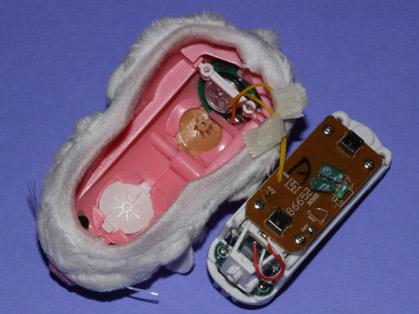
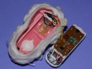
The control logic and sensors are contained in a second module connected to the fur-covered shell. Figure 5 shows the module separated from the shell. You can see the two momentary contact buttons on the top side of the circuit board on the right, and the eight ohm, 1/4W speaker in the rear of the robot shell. The white and tan plastic discs on the shell interface with the two momentary switches on the top of the circuit board. Figure 6 shows details of the nose button assembly. The masking tape is used to hold the twisted wires together and to provide insulation. I would have preferred a soldered connection, but I suppose masking tape is adequate for the low-power audio signal.
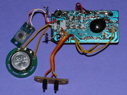
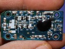
Figure 7 shows the underside of the control circuit board and a view of the two data readers (bottom, left) and the elastomeric nose button (middle, left). A close-up of the control circuit board with the wires removed is shown in Figure 8. The board is populated with SMT components: seven transistors, a voltage regulator, a diode, seven resistors, and two capacitors. The top side of the board holds two leaded electrolytic capacitors and a leaded 1/8W resistor. The heart of the board — the microcontroller — is hidden under the blob of black epoxy.
In case you simply must see what’s under the blob, there are two approaches that I’ve used with good success. The first is to heat the epoxy with a hot air gun and then gently tear at the epoxy with tweezers. When hot, the epoxy has a consistency of putty. The other approach is to use an epoxy solvent — which produces great results. The problem with an epoxy solvent is toxicity – so much so that I advise against it unless you have access to a hooded laboratory work environment and know how to use it. The microcontroller provides the digital to analog conversion for the goofy words and constant chattering of the robot, as well as the switching logic.
Touch the back button and the robot activates and moves about for four minutes before returning to sleep or standby mode. Touch the back button when the robot is active and it goes to sleep. The head button also has dual functionality: it’s a backup button when the robot is on the move and a talk button when in sleep mode.
On my to-do list is installing the circuit board on my Traxx R/C truck, hopefully resulting in a semi-autonomous, cat-size robot pet. I plan to install a Mosfet switch between the truck’s NiMH battery pack and the motors, and drive the Mosfet with the output of the circuit board. I’ll also extend the nose switch to several switches on the bumper of the Traxx truck. The larger issue is how to best cover the robot so that it doesn’t damage itself or the environment. Perhaps a skunk or cat hand puppet will do the trick.
If you manage to successfully repurpose the Zhu Zhu brain, please share your story. NV


Comments