I like to look at patents from the past, and often wonder what the inventor would have done with modern day hardware. I was recently looking at Tesla patents that describe the infamous Tesla coil and wondered how Mr. Tesla would have implemented his concept of wireless energy transmission if he had access to 21st century electronic parts like transistors and dielectrics. I have always wanted to build a Tesla coil, but have been put off by the tedium of tweaking spark gaps and dealing with dangerously high voltages. I decided to try building something loosely based on the original Tesla coil using much lower and safer input voltages that could at least be powerful enough to enjoy Tesla effects such as wirelessly lighting nearby CFLs (compact fluorescent lamps) and to study the concept. This article is a review of how I went about building my own version of a solid-state tabletop Tesla-like coil using common off-the-shelf parts. It won't exactly light a city, but it is a lot of fun to play with.
What Makes This Design So Different?
I am not going to try and cover a detailed explanation and theory behind this technology. Instead, I will ask that you visit any of the many Internet sites that cover the specifics. Suffice it to say that in a conventional Tesla coil, the primary and secondary inductors share the same axis and are located close to one another. In this manner, the magnetic field produced by one inductor can generate a current in the other.
The schematic in Figure 1 shows the basic components of a Tesla coil.
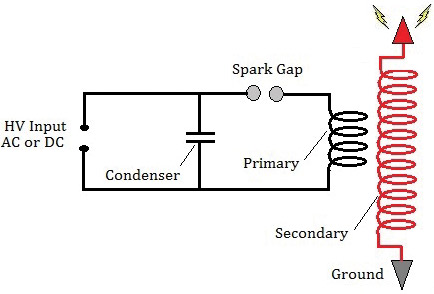
FIGURE 1.
The primary oscillator (or tank circuit) consists of a flat spiral inductor with only a few turns, a capacitor, a voltage source to charge the capacitor, and a switch or spark gap to connect the capacitor to the inductor. The secondary oscillator contains a large tightly wound inductor with many turns, and a capacitor formed by the earth on one end and an output terminal (usually a sphere or toroid) on the other.
A high voltage power supply charges up a capacitor. When the capacitor reaches a high enough voltage, the spark gap fires. The spark gap is like a switch in that it conducts when the voltage gets high and turns off when the voltage gets low. When the spark gap fires, the energy stored up in the capacitor dumps into a 1:100 step-up transformer. The primary is about 10 turns of heavy wire. The secondary is about 1,000 turns of thin wire. With this ratio, if you feed in 10,000 volts, you get out 1,000,000 volts. It all happens at a rate of over 120 times per second, often generating multiple discharges in many directions.
The BaTESLA coil does not rely on a tank circuit for the oscillations and — perhaps best of all — it features auto-tuning. With my design, the PIC generates the frequency and applies it to the primary coil by way of an NPN power transistor which limits the max potential based on the characteristics of the device. Common bipolar power transistors are rated anywhere between 100 to 200 volts. I have found that driving the primary at a high frequency using voltages from as low as a 12V source produces the Tesla-like effects mentioned previously.
More recent designs of the Tesla coil are solid-state devices that utilize power MOSFET transistors or IGBT (Insulated Gate Bipolar Transistor) devices that can create very high potentials without the need for electromechanical devices to transfer power to the primary. These designs are very costly, extremely complex, and very dangerous to work with.
The difficulty of any Tesla design has to involve making the primary and secondary coils resonate. This is where the design described in this article parts company with the older and even most of the contemporary designs. Instead of experiencing the burden of tweaking your design to resonate, my method uses a simple microcontroller to do most of the dirty work.
The software that works with the design automatically adjusts the frequency and duty cycle that produce the greatest output on the secondary coil. This auto-tuning feature allows for a much shorter design time, and will work with practically any coil sizes and ratio of primary to secondary coil windings. The design presented here can easily be modified to generate much higher power levels.
All of the designs produce copious amounts of RF energy which can wreak havoc with nearby unshielded sensitive electronic circuits. This circuit is designed to demonstrate the induction effect without presenting a hazard to nearby electronics, and is unlikely to harm you. Please exercise caution operating this circuit if you have been fitted with a pacemaker or if you have any implanted metallic structures.
Overview of the Circuit
The heart of our circuit is the PIC microcontroller. The schematic shown in Figure 2 is the actual circuit, including the auto tuner.
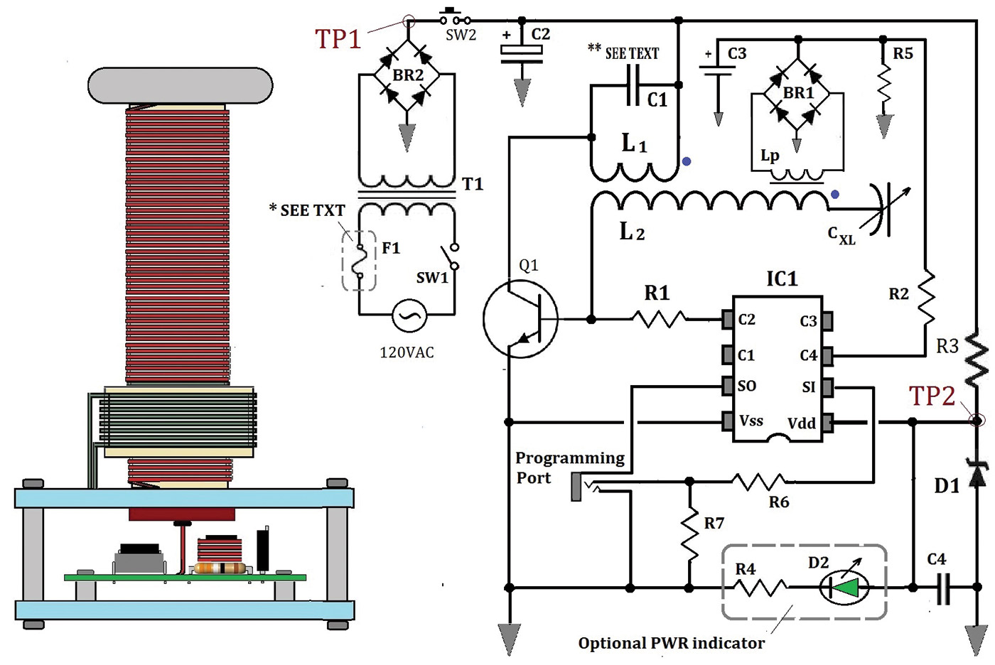
FIGURE 2.
The coils used are fairly simple to construct, but will be the most time-consuming part of the project. The inner diameter of the secondary coil transmitter should not be less than the one used in this project for best performance, and the length should be approximately eight times the inner diameter of the coil. The metallic structure attached to the end of the secondary coil L2 serves as a capacitor and is used to form the LC circuit of the secondary. If you deviate from the design presented here, you will need to experiment in order to discover the proper characteristics of this element.
Constructing the Coils
The secondary coil is wound using 30 AWG wire. The choice of diameter for the coil will dictate how long a single wire must be to create an adequate number of windings for the desired induction effect. If we use too small a diameter, the coil becomes quite tall. With too large a diameter tube, the wire length becomes unreasonable. I have found that tubes with diameters from 1.5 to three inches will allow approximately 450 windings with a length of about eight inches. With a 1.5 inch diameter, 450 windings will require close to 200 ft of enameled magnet wire.
Hobby electronic stores sell small spools of magnet wire at the lengths required for this project. The tube I used for the secondary coil for the prototype was sold as a container for multiple spools of thread, but any similar size tube (such as PVC pipe) will work just fine.
Begin construction by taping one end of the wire to the form approximately one half to one inch from the end, leaving a six inch length of wire. Wind the turns with tension applied such that the windings are not loose and spaced as close together as possible as shown in Figure 3.
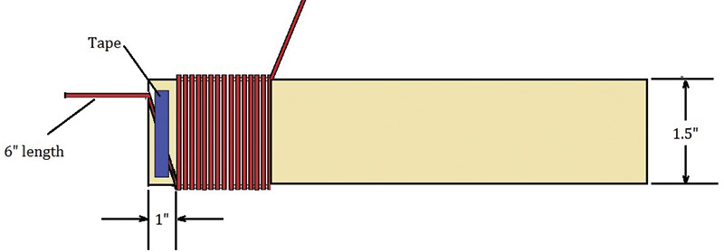
FIGURE 3.
Cut small segments of tape ahead of time to use for any breaks in the winding process. When finished winding the secondary coil, tape the end winding in the same way as the beginning winding. Remove any temporary tape used in between the first and last winding, and spray the coil with an aerosol clear acrylic and let it dry. (Most acrylic sprays require about 30 minutes of dry time.) Drill three small holes at either end of the tube to create a strain relief that will allow connection of stranded wire to the magnet wire as shown in Figure 4.
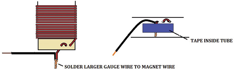
FIGURE 4.
The primary coil is very easy to construct. Surface area is the most important metric which can be accomplished using either large diameter insulated wire or copper tubing. The position of the primary can be at any point around the secondary.
Looking at the schematic, you can see that the primary and secondary coils are polarized. If you wind the secondary in a clockwise manner, the primary coil will need to be wound clockwise also for induction to occur. Look in the PVC section of your local hardware for primary coil forms. A good choice for the form would be an expansion or reducing coupling of about two to three inches. Wrap two to three turns of wire used for 120V power cord around the form as shown in Figure 5.
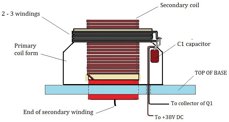
FIGURE 5.
How Does the Self-Tuning Work?
The coil pair is made to resonate by the oscillating DC potential applied to the primary coil. This is accomplished through the collector connection made to one end of the primary to the circuit input power supply. Power is created by regulating the output of a 24 volt transformer, and is used to power the primary coil. The base of the driving transistor is switched on and off by pulse width modulation (PWM) using the C2 pin on the PIC. A simple program running on the PIC sweeps a frequency range as it samples the output of a small ferrite core inductor mounted under the secondary.
Current is induced in the small pickup coil which is located within the EM field of the secondary, acting as a power receiver as shown in Figure 6.
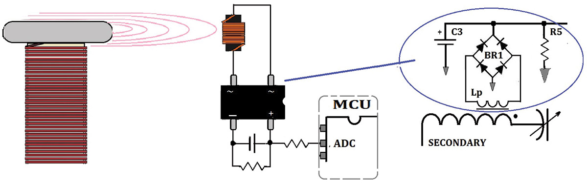
FIGURE 6.
Feedback from the voltage that develops on the small inductor is fed to an ADC (analog-to-digital controller) pin on the controller. The supply voltage acts as a reference to the incoming value and divides this analog voltage into a digital range from zero to 255. If the supply is three volts, an incoming voltage of 1.5 volts reads 127, or half the reference voltage. As soon as the regulated output from the receiver reaches the same or greater value of the potential applied to run the microcontroller, it locks on to that frequency. If you construct the coils close to the specifications given, the primary will induce a great deal of power with a considerable bandwidth of about 3 kHz or greater on either side of the resonant frequency. You should notice wireless power to the CFL starting as low as 700 kHz and as high as 3 MHz.
Circuit Construction
The entire circuit can be made to easily fit on a raised platform that supports the primary and secondary coils. To construct a design like the one shown here, you will need the following pieces of hardware and tools. Start the design by cutting a 3.5 inch square piece of prototyping board and drill 1/8” holes in the corners as shown in Figure 7.
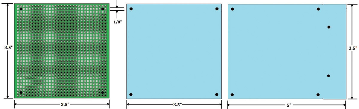
FIGURE 7.
The base for the design is made from 1/8” Lexan or similar plastic material. Cut two pieces of the Lexan into one 3.5” square and one 3.5” x 5” size, and drill 1/8” holes in the corners by using the printed circuit board (PCB) as a guide. Using eight one inch threaded aluminum standoffs, mock assemble the PCB and Lexan squares as shown in Figure 8 to make sure everything aligns properly.
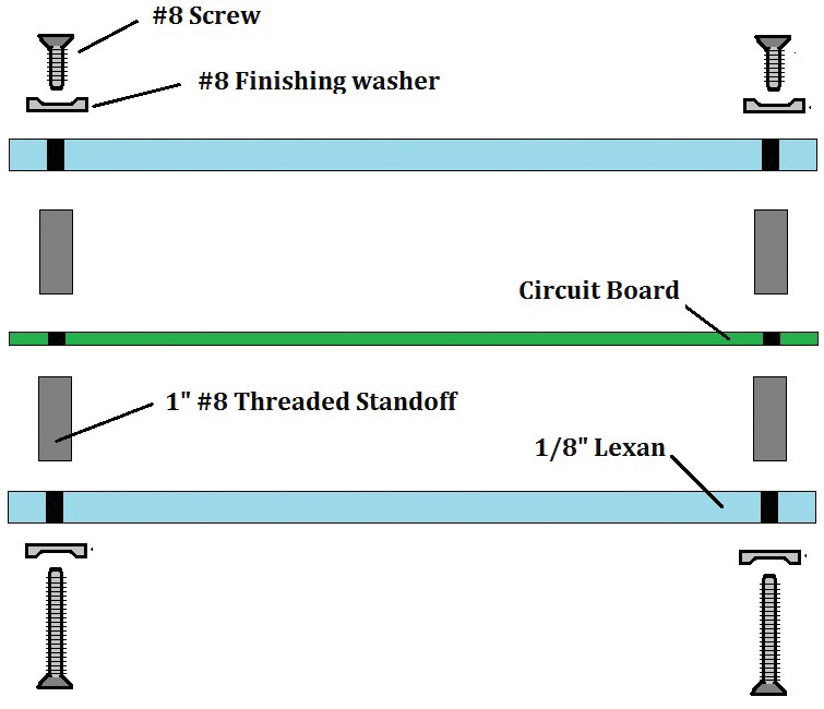
FIGURE 8.
The one most important consideration is the inclusion of the power supply. I designed the prototype for this design with an onboard transformer which requires tall enough standoffs that provide clearance. I also made provisions for an off-board supply by using a rectified input jack as noted in the schematic. This allows you to experiment with different supplies to the circuit. The tube for the secondary coil is mounted to the upper Lexan piece by gluing one of the end caps to the 1.5” hole cut in the plastic as shown in Figure 9.
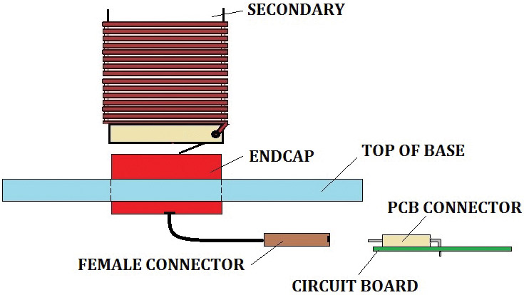
FIGURE 9.
Drill a small hole in the bottom of the tube cap and feed the six inch length of wire through it for connection to the PCB. I used a SIP male and female connector pair for convenient connection to the circuit board. I constructed the toroid for the coil from the bottom of two soda cans. To create the toroid, saw one inch of the bottom of two aluminum cans and sand off the labels from both halves along with the plastic coating from the insides. Drill a hole in the center of both bottoms; when the cans are fitted together, you should be able to test connectivity from top to bottom using a multimeter. Cut a corresponding hole in the center of the other tube end cap and assemble the two bottom halves of the cans as shown in Figure 10.
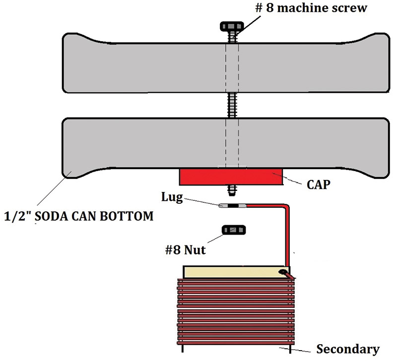
FIGURE 10.
A solder lug is a convenient way to make the connection to the end of the coil. After connecting the toroid, check for connectivity from the bottom wire of the secondary to the top of the toroid. The resistance should be the same as the ohm value of just the coil by itself. You can attach a wire or metal piece with sharp edges to the top-most point on the toroid to provide a breakout point for corona discharge if you like (illustrated in Figure 11). If you construct the primary to secondary geometry correctly, the corona should self-discharge without a nearby ground path.
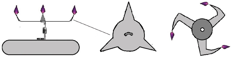
FIGURE 11.
Try attaching thin pieces of aluminum or tin geometries that have intentionally designed sharp points for the best corona effects. Use wire or a stiff lead component to elevate the metal shape. The intensity of the corona is a function of the capacitance of your toroid. A pinwheel design using a circular array of points will actually spin as charge leaves the sharp edges.
Constructing the Printed Circuit Board
The parts layout for the PCB is not critical. If you mount the 25V transformer on the base, you may want to contour the PCB for it to fit as shown in Figure 12.
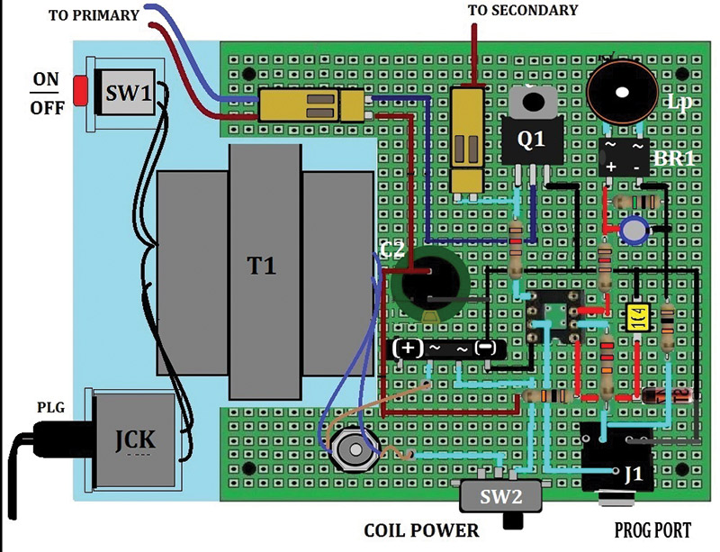
FIGURE 12.
The power jack located in the lower left corner of the PCB is a parallel connection to the 25V AC output of the transformer. It can be used for an alternate input voltage source.
The 120V input to the transformer connects to the circuit using a molded two-pin connector. The RF may interfere with programming, so you may want to open the +V supply to the coil using an optional SPST switch shown in the schematic. This allows a programming voltage to be present on the controller, but disables the coil output. The C4 capacitor that connects across the coil should be placed as close as possible to the primary. This large capacitor can be integrated into the coil form used for the primary. This high voltage capacitor is important and for best operation, it should be able to withstand a minimum of 1,600V potential.
The capacitor is constructed from metalized polypropylene and is specially designed for horizontal resonance circuits for color TVs and monitors. These capacitors can be hard to find and expensive to buy, and are best salvaged from the circuit boards of a monitor or TV.
How to Demonstrate It
A high voltaic potential will accumulate on the capacitive structure on the end of the secondary coil. By convention, it is usually constructed in the shape of a sphere or toroid to avoid sharp edges. Most all Tesla coils demonstrate beautiful electrical arcs or coronas that are discharged from the toroid by using some kind of breakout point. The size of the toroid you construct will make a difference in how the electricity is discharged. If you use a smaller toroid, electricity will be discharged more rapidly, but the arcs will not be as long. If you use a larger toroid, electricity will be discharged less rapidly, but the arcs will be much longer.
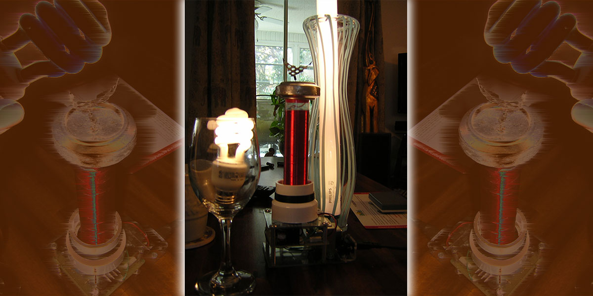
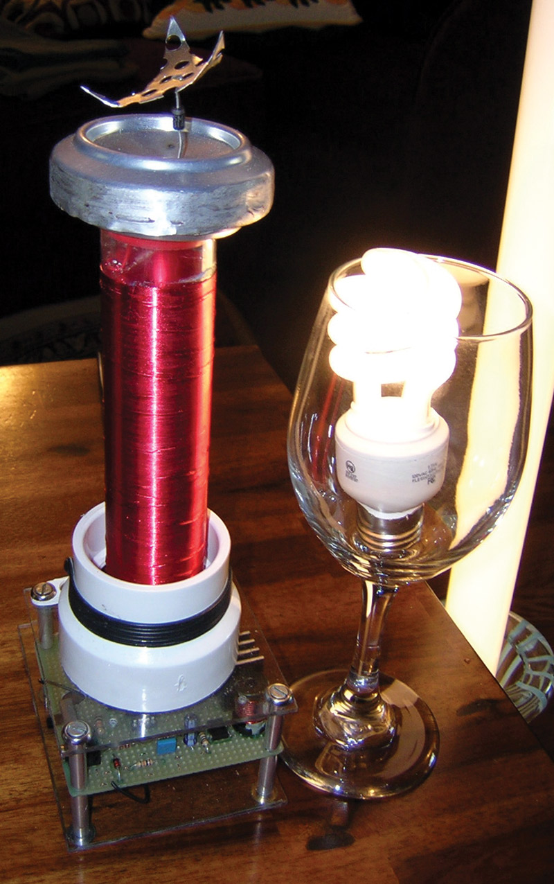
The next most popular demonstration would be the wireless lighting of gas filled tubes such as flourescent or even neon. I have purposely kept the power low on this design for safety, but you should be able to see one to three inch coronas from the toroid if you attach a breakout point. With as little as 12V input to the primary, a five foot CFL glows very brightly, drawing as little as only 100 mA. At 30 volts, the coronas are very pronounced and make a hissing sound, and just begin to influence nearby electronics. There is little risk of an electric shock but there may be a risk of RF burns from nearby metals. The material is not heating but is actually arcing to the skin at high frequencies.
Software
The code driving the coil is the small Basic program in Figure 13.
setfreq m32 ‘remark setfrequency 32 Mhz
b2 = 3 : b4 = 8 ‘remark set intial values for b2 and b4 (2 Mhz, 50% duty)
symbol FRQ = b2: symbol DUTY = b4 ‘remark symbolize variables FRQ and DUTY
Do while b0<255 ‘remark loop until voltage on pickup coil is maximum
readadc c.4,b0 ‘remark read the voltage on pickup coil
Gosub TESLA ‘remark jump to PWMOUT routine
Loop
TESLA:
DUTY = DUTY + 1 ‘remark increment DUTY cycle
FRQ = FRQ + 1 ‘remark increment FREQUENCY
PauseUs 1200
PWMout 2, FRQ, DUTY ‘remark frequency generated on pin C.2
PauseUs 1200
If b0>150 then TESLA ‘remark If voltage on pickup-coil is MAX, repeat loop
return
FIGURE 13.
Voltage Check
1) The first voltage point indicated as TP1 on the schematic should be approximately 38V DC. If no voltage is present, check that there is 120V AC on the primary side of the transformer. If the 120V AC is present, check for continuity to the AC terminals of the bridge rectifier marked ~. There should be an AC voltage of approximately 24V AC. If this voltage is present, check for continuity to the electrolytic C2. If the capacitor is connected correctly, the rectifier may be defective.
2) The second voltage point labeled TP2 should measure about 3.7V DC that powers the 08M2. If no voltage is present, check the orientation of the zener diode Z1. If the diode is installed correctly, check that resistor R3 is connected to the +V DC potential on TP1.
Conclusion
Even though the design has been intentionally engineered to be safe, there is always the potential for electric shock. If you are unsure about working with any portion of the circuit, please seek help with the design from a more experienced person. I hope this project will spark your interest. NV
PARTS LIST
| ITEM |
QTY |
DESCRIPTION |
|
| SW1 |
1 |
Toggle Switch |
|
| SW2 |
1 |
Slide Switch |
|
| T1 |
1 |
25V Transformer |
|
| Q1 |
1 |
TIP3055 NPN |
|
| HS |
1 |
TO-220 Heatsink |
|
| R1,2 |
2 |
120 ohm 1/4W |
|
| R3 |
1 |
10K ohm one watt |
|
| R4 |
1 |
220 ohm 1/4W |
|
| R5 |
1 |
1 megohm 1/4W |
|
| R6 |
1 |
10K ohm 1/4W |
|
| R7 |
1 |
22K ohm 1/4W |
|
| F1 |
1 |
0.5 amp Fast Blow |
|
| FH |
1 |
Fuse Holder |
|
| IC1 |
1 |
08M2 PICAXE |
|
| ICS |
1 |
Eight-pin IC Socket |
|
| D2 |
1 |
3 mm Green LED |
|
| Lp |
1 |
1,000 µH Choke |
|
| BR1 |
1 |
Bridge Rectifier |
|
| BR2 |
1 |
Bridge Rectifier |
|
| J1 |
1 |
Programming Jack |
|
| Z1 |
1 |
4.7V Zener Diode |
|
| PCB |
1 |
Gen Purpose PCB |
|
| C2 |
1 |
100 µF 200V Cap |
|
| C3 |
1 |
1 µF 50V Electrolytic |
|
| C4 |
1 |
.01 µF Capacitor |
|
| JCK |
1 |
120V Power Jack |
|
| PLG |
1 |
120V Power Cord |
|
| C1 |
1 |
1 µF Metallized Polypropylene Film Capacitor (see text) |
| Misc. Hardware: |
| 1/8” Lexan material |
| 200’ 30 AWG Magnet Wire |
| L3 Coil Form 2-3” diameter non-metallic tube |
| L2 Coil Form 1.5” diameter non-metallic tube with caps |
| Threaded Standoffs with associated mach screws |