LEARN HOW THE NUMBERS ‘1’ AND ‘0’ CHANGED THE WORLD
This article was written specifically for the newcomer to the field of digital electronics. If you’ve always wanted to know how the digital world works, then keep reading. You don’t need to know calculus, algebra, or any complex formulas to finish this article. The only requirements are an interest in digital electronics and a desire to learn. Since you’re reading this paragraph, obviously you’re at least a bit curious about the digital world. Fortunately, curiosity is half the battle to enlightenment.
Analog vs. Digital
The world of electronics is a lot easier to understand if we start by dividing it into two distinct categories: the “analog” world and the “digital” world. The analog world generally refers to any natural phenomenon that varies its own properties over a period of time. Take the outside temperature, for example. We notice that it changes rather slowly throughout the day, and at any instant we can measure how hot or cold it really is by using a simple thermometer.
The same changing properties can be observed, measured, and recorded in other natural phenomenon such as barometric pressure, wind speed, solar radiation, etc. If you were to record and graph each of the above events over a 24 hour period, you would notice one similar characteristic: the physical properties of each phenomenon change over time.
In each case, if you connect all the dots on a graph, the results will always form some type of “analog signal” (wave) like these examples:
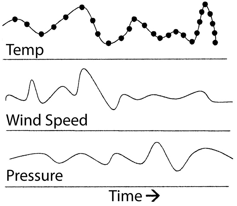
It’s the job of the analog electronics engineer to deal with many of these thermal, magnetic, optical, acoustical, biological, chemical, or electrical “signals” by designing the appropriate analog sensors and control circuitry.
The Digital World
Digital electronics, on the other hand, are a completely different type of animal altogether. How is the digital world different from the analog world? Well, in the digital realm (i.e., digital electronic circuits), there are only two “states” that are important: ON or OFF. For example, when you flip the light switch on in your bathroom, you know there are only two possible positions the light switch can be in (yep, ON or OFF). It’s of no real concern to you that there could be 110, 113, 120, or 125 volts (i.e., fluctuating analog “signal”) running through the electrical wiring connected to the light switch.
The important thing to remember is switching the light on not only performed some useful work (light up the bathroom), but it also conveyed some real basic digital information as well — that the light was ON and not OFF. This ON/OFF code is exactly how the world of digital electronics operates. As you will see later, this ON/OFF switching is the same logic used to build the digital electronic circuits inside your laptop computer, GPS device, and smartphone. Take a look at Figure 1 so the difference between analog and digital worlds is clear in your mind.

FIGURE 1.
Figure 1a is a graph showing how electricity (voltage level) in your home changes over the course of 12 hours. At one point during the 12 hours, we can see that the voltage level at 2:00 pm was 110 volts. At 4:00 pm, it changed to 120 volts. In Figure 1b, on the other hand, we have a light switch that can be turned ON or OFF during the day. Notice that in Figure 1b, the light switch was turned ON at 2:00 pm and then turned OFF at 4:00 pm. Then, again it was turned ON at 7:00 pm and then turned OFF at 9:00 pm.
In this example, it doesn’t matter much what voltage level is present throughout the electrical circuit (105V, 110V, 115V, 120V). What is important here is the “information” conveyed in Figure 1b — whether or not the switch was ON or OFF. This “instantaneous” ON/OFF electrical switching is commonly referred to as a “digital” signal.
[Author’s note: Not to confuse you, but — and this is very important — digital electronic circuits run on 1.5-15 volts of Direct Current (DC) — not the 110 volts Alternating Current (AC) that comes out of the wall outlet in your home. The AC voltage level in Figure 1b was only used to show how a digital signal looks (square wave) when compared to an analog signal (i.e., the fluctuating wave in Figure 1a).]
Digital — On or Off
To see how a light switch can transmit digital information, let’s suppose that you told a friend on the phone that if she happens to drive by your house later and notices that your porch light is OFF, you’ve got company — don’t come over. However, if the porch light is ON, she should drop in. As you can see, this little “code” allows you to use one light to convey two messages. Now, let’s take this idea a little further and use two lights.
If you tell your friend when she sees the bedroom light OFF and the porch light OFF, it means that your parents are still at home — so, again, don’t come over. However, if the bedroom light is ON and the porch light is OFF — stop over. Also, if she sees that the bedroom light is OFF and the porch light is ON, it means you’ll meet her at the pizza shop.
Then finally, if the bedroom light is ON and the porch light is ON, you’ll meet her later at Sue’s house. Notice that this time, with only ‘two’ lights (switched ON or OFF), you transmitted ‘four’ messages (see Figure 2).
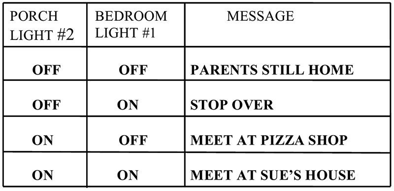
FIGURE 2.
The question here is: How many messages can you signal to your friend if you used four lights instead of two? Check out Figure 3 for the answer.
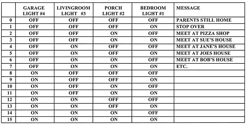
FIGURE 3.
Since there are four lights and only two “states” or positions the light switch can be in (ON or OFF), there’s a maximum of 16 messages (2 to the 4th power or 24 = 2x2x2x2) that you can relay to your friend. Obviously, with 16 messages, you and your friend would need a list of instructions to decode each sequence of lights.
Notice in our previous example how information was conveyed (transmitted) by using a simple light switch that was limited to only two positions or “logic states” (ON or OFF). Once again, it didn’t matter how much electricity was flowing in the porch, bedroom, garage, or living room light circuits.
The two most important factors to remember here are whether or not the lights were ON or OFF, and in what sequence or position the lights were in.
As you can see, digital electronics are based on a “switching logic” (ON or OFF). On the other hand, analog electronics are more concerned with a fluctuating (constantly changing) electrical quantity like voltage and/or current. If necessary, refer to Figure 1 again so the difference between digital and analog signals is clear in your mind. This is a very important concept to understand, so don’t continue reading until you make the distinction between analog and digital information/signals.
Binary System
In our previous examples, we saw how the digital electronics world operates by limiting itself to two states. The binary (bi = two) numbering system also deals with two states, or numbers: 1 and 0. As you will see, binary numbers are very important and useful in the realm of digital electronics.
Now, suppose we take our previous four light example (Figure 3) and instead of using an ON or OFF code, we substitute a ‘1’ for ON and a ‘0’ for OFF. Figure 4 shows how our message chart looks after this change.
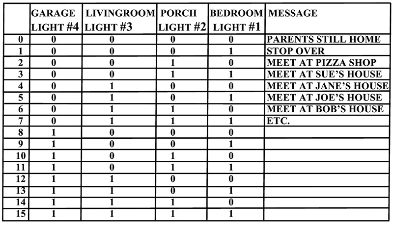
FIGURE 4.
It may appear to you that the ON and OFF arrangement in Figure 3 and the 1 and 0 layout in Figure 4 were picked at random. The fact is that the ones and zeros you see in Figure 4 just happen to be the way you count in ‘binary.’ (Remember, the binary numbering system is based on the number ‘two:’ 20 = 1, 21 = 2, 22 = 4, 23 = 8, 24 = 16, etc., and our decimal numbering system is based on the number ‘ten:’ 100 = 1, 101 = 10, 102 = 100, 103 = 1000, 104 = 10,000, etc.)
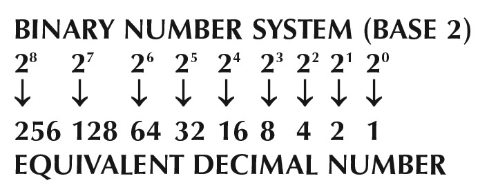
Here’s how the binary number system works:
For example, let’s convert the binary number 1101 from the list in Figure 4 to its decimal (base 10) equivalent:
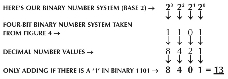
In this example, the binary number 1101 is equal to he decimal number 13.
There are four key points to learn from this example:
- Notice how the ‘decimal’ numbers 1, 2, 4, and 8 ‘double’ in value for each increase in power in the binary number system (i.e., Binary 20 = Decimal 1; Binary 21 = Decimal 2; Binary 22 = Decimal 4; Binary 23 = Decimal 8, etc.).
- Notice that each binary number 1 or 0 holds a “position” or “weight” in the binary numbering system. In other words, in the digital world, 0 is just as important as 1.
- Notice that each position in the binary numbering system equals an exact decimal number value (1, 2, 4, 8, 16, 32, 64, etc.).
- Notice that you only add the decimal number values together whenever there is a 1 in the binary number.
Let’s convert one more binary number into a decimal number before moving on. Convert 1010110 to a decimal number:
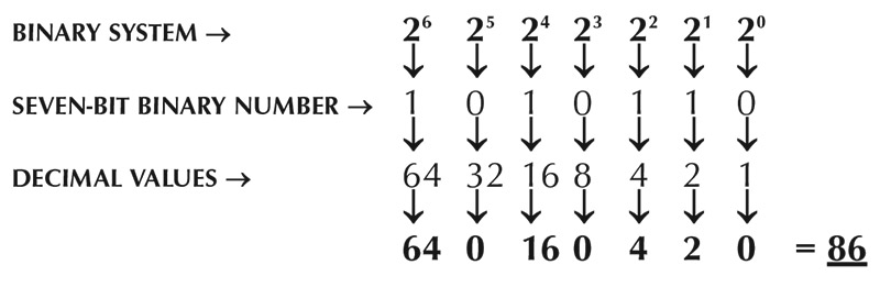
Once again, notice that although each zero in the binary number 1010110 holds a place and is very important, its decimal value is ignored when we add all the decimal numbers together (total = 86).
These examples should give you an idea as to how the list of binary numbers in Figure 4 was created. Originally, we used ON and OFF light switches to transmit coded messages (Figure 3). Now, instead of messages, we can convert binary numbers into their decimal equivalent.
If you’re asking yourself what this has got to do with digital electronics, you’ve asked a very important question. If you remember what we said about digital logic (that it is a switching logic — ON or OFF), you can probably see that transmitting these binary ones and zeros over an electrical wire is just a matter of “switching” an electrical voltage ON and OFF (five volts = 1, zero volts = 0). Remember, you can only do two things with electricity: you can switch it ON or you can switch it OFF.
For example, let’s say we wanted to send the decimal numbers 72, 69, 76, and 80 from a computer in one office to a computer in another office. All we need to do is change each decimal number 72, 69, 76, and 80 into a binary number, convert these binary ones and zeros into an electrical signal (five volts = 1, zero volts = 0), and then send this digital code over an electrical wire (see Figure 5).

FIGURE 5.
If you study Figure 5 for a while, the answer to your original question (What has the binary numbering system got to do with digital electronics?) will become apparent. Figure 5 shows how decimal numbers 72, 69, 76, and 80 and their binary equivalent are transformed by the computer into a digital signal (zero volts and five volts) and then are transmitted over an electrical wire. The digital electronic circuitry inside computer #2 converts the voltage levels (zero volts and five volts) into binary ones and zeros, and then displays (LCD monitor) that information in alphanumeric characters so we can understand the original message.
As you might have suspected, the numbers 72, 69, 76, and 80 in the example above were not picked out of the air. If you look at any American Standard Code for Information Interchange (ASCII) table, you’ll see that the number 72 = H, 69 = E, 76 = L, and 80 = P is a code for the word HELP.
What’s important about this example is the fact that we can transform the word HELP into decimal numbers, then into a binary code of ones and zeros, and finally into digital voltage levels that can travel over an electrical wire. Just think about it. This all started by flipping a bathroom light switch ON and OFF!
Now that you know the digital world is controlled by binary numbers (1 or 0), it’s time to use this binary system to build some digital logic gates. You’ll really see how important binary numbers are to digital circuits after reading the next section.
Digital Logic Gates: The Building Blocks of All Digital Electronic Circuits
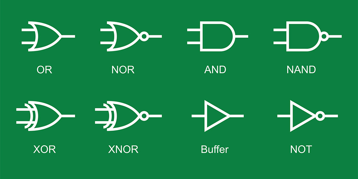
Understanding digital logic gates is a major prerequisite to learning how all digital electronic circuits work. Basically, there are three types of electronic “logic gates:” the AND gate, the OR gate, and the NOT gate. (Actually, there are a few more types of gates, which we will cover later in this article.) Just remember, logic gates are the main building blocks of all digital logic circuits.
The AND Gate
Let’s analyze the AND gate in Figure 6 first. Take a look at the logic symbol for an AND gate in Figure 6a.
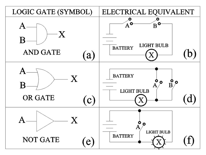
FIGURE 6.
It has two inputs (A and B) and one output (X). The AND gate operates (logically) in the following way: If there is a binary 1 on input A and a binary 1 on input B, the binary output (X) will equal 1. If input A has a 1 and input B has a 0, output (X) equals a 0. In turn, if input B has a 1 and input A has a 0, then the output (X) will be a 0. Lastly, if input A has a 0 and input B has a 0, then output (X) will also be a 0.
Okay now, let’s build an electrical circuit that mimics this AND gate logic. Take a look at the electrical circuit in Figure 6b. We have a nine volt battery, a light bulb, and two switches. Notice that if we close switch A, the light will NOT turn “ON” because switch B is open (i.e., the electric light is not connected to the battery).
If switch B is closed and switch A is open, the light remains OFF. Notice that the only time the light will turn ON is when switch A ‘AND’ switch B are closed.
Now, look at Figure 7b and you should see that our old friend the AND logic gate operates in the same way as our electrical light circuit in Figure 7a. You can see this very important point by looking at the two logic tables in Figure 7.
Notice in Figure 7b that the ones (1) in the logic truth table match (same position) the “closed” switches in the circuit truth table of Figure 7a.
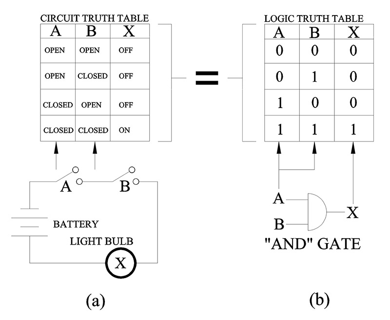
FIGURE 7.
It’s important that you understand how the AND gate logic symbol in Figure 7b and the electrical circuit in Figure 7a are related. Notice in Figure 7b how the binary number system comes into play here. The only time output (X) equals a 1 is when both A and B inputs are also a 1. The only time the light turns on in Figure 7a is when both A and B switches are closed.
Okay, the question here is what happens if we change the ones and zeros in Figure 7 into digital electronic signals (1 = five volts, 0 = zero volts)? Look at Figure 8 and you’ll get the answer to this question.
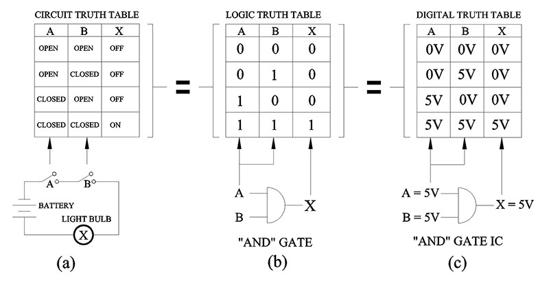
FIGURE 8.
Looking at Figure 8c, you can see that although we changed the binary ones and zeros to five volts and zero volts, the truth tables are all the same. This means that the electrical circuit with two switches A and B (Figure 8a) operates like the AND gate logic truth table in Figure 8b and Figure 8c.
You’re probably asking yourself, “Do I need all these truth tables, AND gates, and 1 and 0 logic to understand digital electronics?” The answer to that question is YES! The entire digital world is based on knowing what the input and output values will be for any digital logic circuit.
For example, look at the 7400 integrated circuit (IC) in Figure 9. You can purchase this IC on the Internet and verify that it works exactly like the truth tables we’ve constructed.
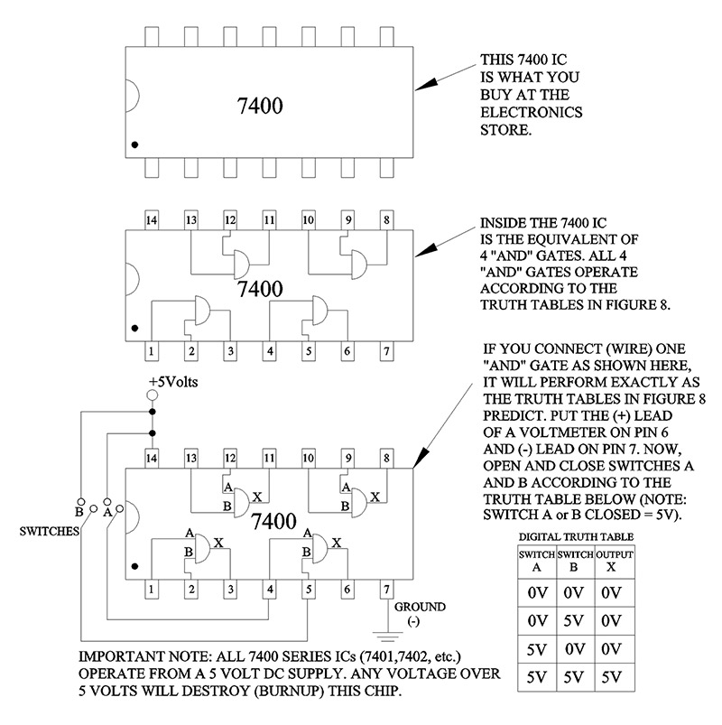
FIGURE 9.
Built into the 7400 IC is the same AND gate we’ve been talking about in Figure 7 and Figure 8.
If you connect the 7400 IC as shown in Figure 9, you can prove to yourself that the five volt and zero volt truth table in Figure 8c are correct. More importantly, though, you’ll see how digital logic gates and truth tables are used to create digital electronic circuits.
Now that you understand how an AND gate works, let’s use this electronic AND gate in a real world application. Let’s say we have an elevator with two doors that absolutely must be closed before the elevator starts to move up or down. Each door has an electrical switch (A and B) that is connected to an AND gate.
The output (X) of the AND gate is connected to an electric motor that moves the elevator up or down.
Our job is to make sure that the only time the elevator is allowed to move is when both doors are completely closed. Let’s set up a truth table for what we want the elevator to do (see Figure 10). Notice how we created the table in Figure 10. We determined how the output (X) (motor ON or motor OFF) should respond according to the position of each door (OPENED or CLOSED).
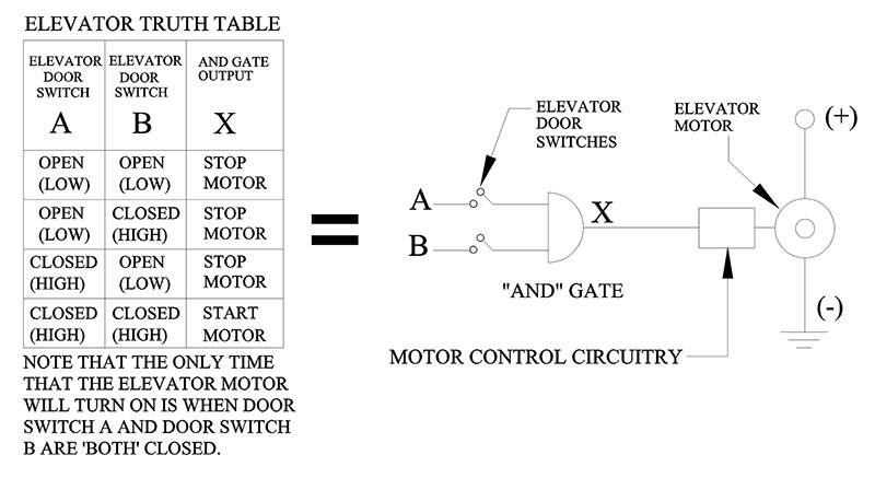
FIGURE 10.
Also notice (Figure 11) that the elevator truth table is the same as the AND gate truth table and our logic (binary) truth table.
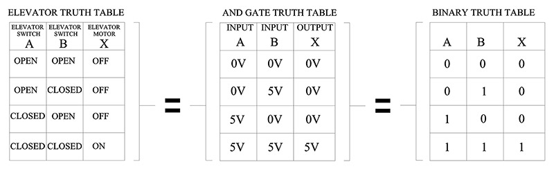
FIGURE 11.
It should be apparent by now that the AND gate and its truth table can be used to design and build digital electronic circuits that have real world practical applications.
Now, let’s look at our next gate: the “OR” gate.
The OR Gate
As mentioned earlier, the AND gate is one of the three basic logic gates (AND, OR, NOT). Let’s see how the OR gate differs from the AND gate.
Looking at the electrical circuit in Figure 12, you’ll notice that two switches (A, B) are connected in parallel. Notice that if switch A is CLOSED, it will complete the electrical circuit and light (X) will turn ON.
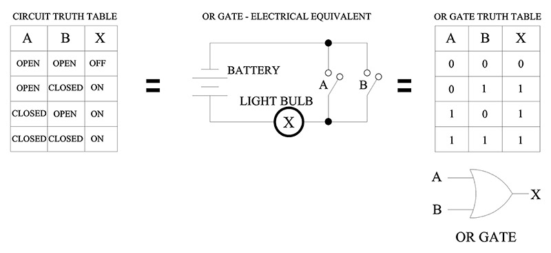
FIGURE 12.
Now, if switch A is OPEN and switch B is CLOSED, the light will also turn ON. If both switches are CLOSED, the light is also ON. Notice that as long as one switch (A OR B) is CLOSED, the light will turn ON.
The only time the light turns OFF is when both switches are OPEN. Study Figure 12 until you see how the OR Gate Truth Table matches the Electrical Circuit Truth Table.
Let’s take a look at a practical application for the OR gate. An OR gate circuit can be used to protect a house from a burglar. Figure 13 shows a simple alarm system based on the OR gate.
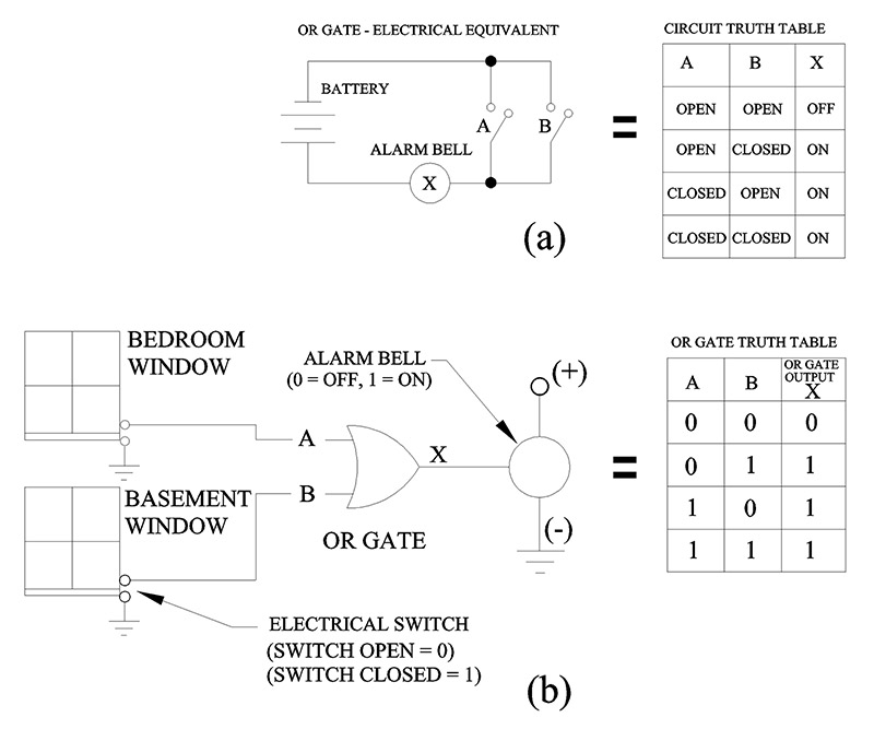
FIGURE 13.
It’s easy to see in Figure 13b that if the bedroom switch (A) is CLOSED (window is open) “OR” the basement window switch (B) is closed, the alarm will sound. Notice in the OR gate truth table (Figure 13b) that switch A OR B can turn the alarm ON.
As you can see, the OR gate logic truth table can be used to design a burglar alarm system just as the AND gate logic truth table was used to start and stop an elevator motor.
Take a look now at Figure 14 so you can see the difference between an AND gate and an OR gate.
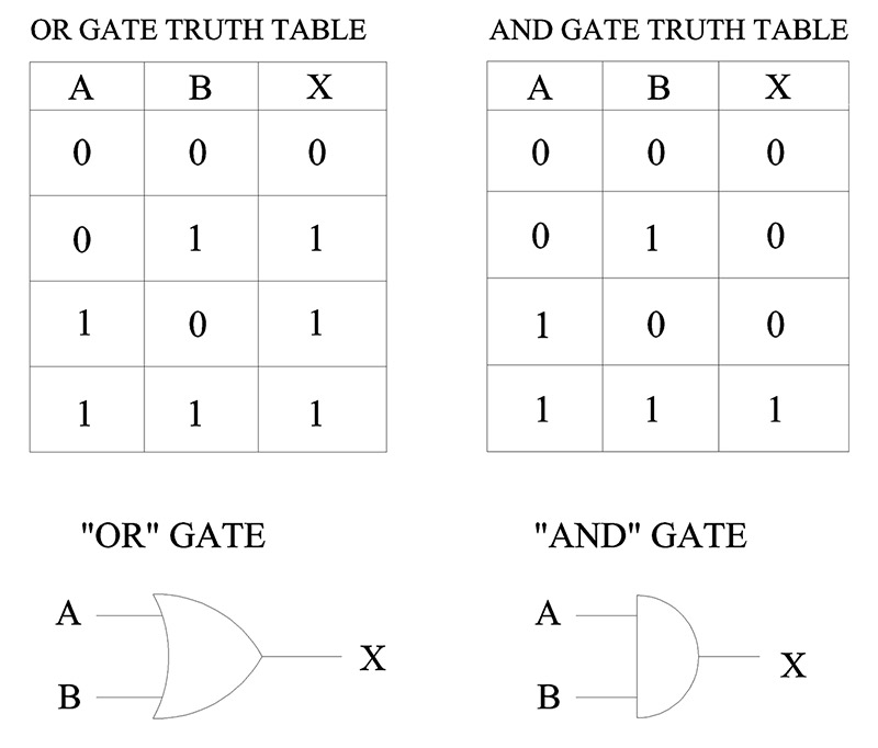
FIGURE 14.
Notice the major difference between the OR gate and the AND gate. The OR gate will output a one (1) when either input A OR B is a 1, whereas the AND gate will only output a 1 when both inputs A AND B are a 1.
The NOT Gate (Inverter)
Let’s turn our attention to the last of the three basic gates: the NOT gate (see Figure 15).
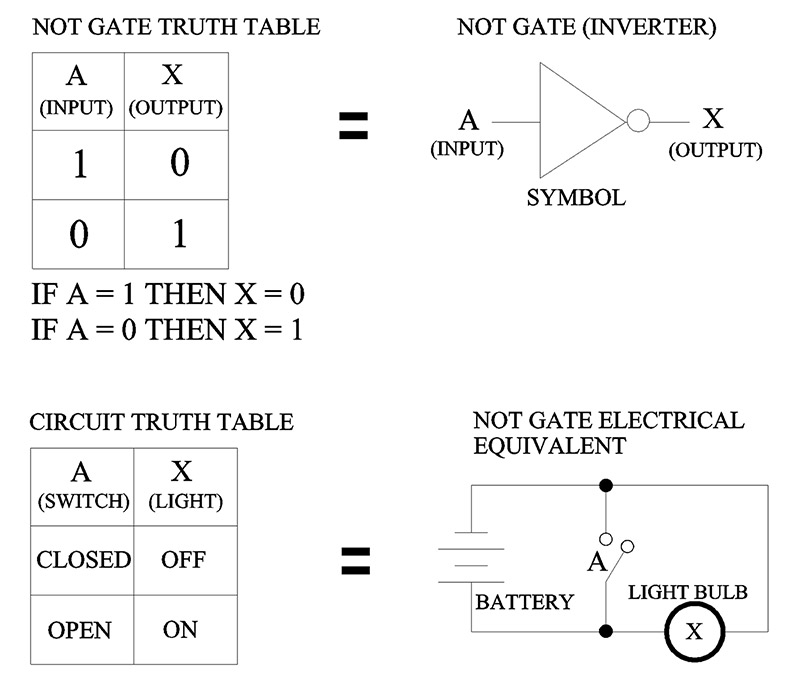
FIGURE 15.
The NOT gate is commonly called an “inverter.” It has one input (A) and one output (X). If the input to a NOT gate (A) is a 1, the output will be a 0. Conversely, if the input to a NOT gate (A) is a 0, then the output will be a 1. You can see now why they call the NOT gate an ‘“inverter.”
To get a better understanding of how the NOT gate works, look at the electrical circuit in Figure 15. Here, if switch A is CLOSED, the electrical current from the battery will bypass the light; consequently, the light will not have enough current to turn ON.
However, if the switch (A) is OPEN, the light will remain ON because the electrical current bypasses the switch and travels directly to the light. The NOT gate is used extensively in digital logic circuits.
Next, you’ll see how it can change the AND gate and the OR gate into NAND and NOR gates.
Inventory
It’s time to take inventory of just how much we’ve learned so far. You might not have realized it, but some very important concepts were tackled. You started with a simple bathroom wall switch that turned a light ON or OFF. You transformed these ON and OFF digital signals into a binary code of 1 and 0. You learned about AND, OR, and NOT logic gates and their associated truth tables.
Finally, you converted all those ones and zeros into electrical circuits with real world applications. Good work!
The NAND, NOR, EX-OR, and EX-NOR Gates
In the previous section, I mentioned how important the NOT gate was in digital electronic circuits. Now, you’ll see how the NOT gate is used to create both NAND and NOR gates. In addition, we’ll cover two other special gates used throughout the digital electronic world: EX-OR and EX-NOR gates.
The NAND Gate
Let’s start with the NAND gate. The NAND (Not AND) gate is basically an AND gate with a NOT gate (inverter) connected to its output (see Figure 16).
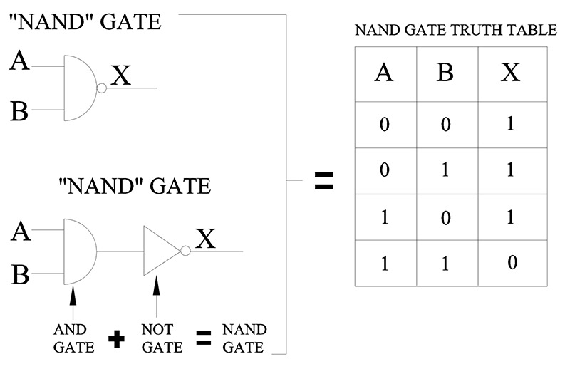
FIGURE 16.
Notice the circle at the output (X) of the NAND gate in Figure 16. This circle is the standard symbol in digital electronics to indicate inversion (NOT = INVERTER). It is equal in logic to the NOT gate with its triangle and circle symbols.
So, from now on, anytime you see a circle on the input or output of an gate, it means that you should invert the signal or logic (1 to 0, 0 to 1, zero volts to five volts, five volts to zero volts, HIGH to LOW, LOW to HIGH).
As you can see in Figure 16, the truth table shows that the only time the output of a NAND gate will be 0 (or LOW) is when both inputs A and B are a 1 (HIGH). Also notice in the truth table that any 0 (LOW) on input A or B will make the output (X) a 1. In other words, any 0 (LOW) on the input of a NAND gate will produce a 1 (HIGH) at the output (X).
Like the AND and OR gates discussed previously, let’s use the NAND gate in a practical real world application. Suppose we build a NAND gate electrical circuit that monitors two outdoor security lights so that if either light goes out (OFF), an alarm sounds. Once again, the first thing we do is set up a truth table for our light circuit (see Figure 17).
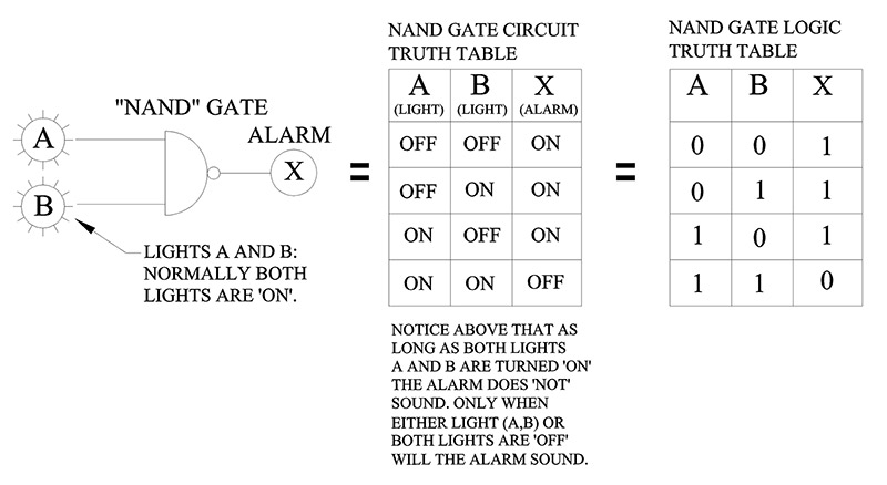
FIGURE 17.
Notice again in the truth table, that if ‘either’ light A or light B turns OFF, the alarm will turn ON. You should also see that the alarm will remain OFF only as long as ‘both’ lights are ON.
The importance of truth tables in designing electronic circuits cannot be overstated. In any digital electronic circuit that employs logic gates (AND, NOT, OR, NAND, etc.), you must define what you want the circuit to do. Obviously, the best way to see what the input and output logic of your circuit will be is to set up a truth table.
Let’s move on to our next gate now: the NOR gate.
The NOR Gate
Once again, the truth table in Figure 18 tells us exactly how the NOR gate works. The only time the output (X) of a NOR gate will equal a 1 is when ‘both’ inputs A and B are 0. Another way to say it is when both inputs to a NOR gate are 0 (LOW), the output of a NOR gate will be 1 (HIGH).
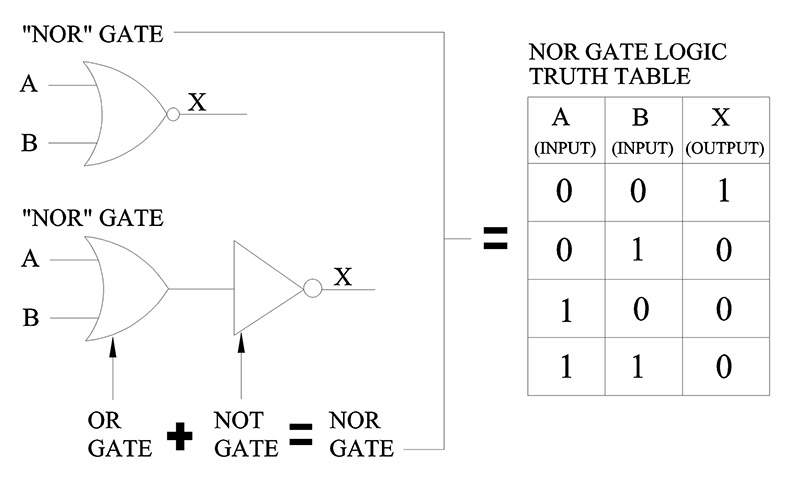
FIGURE 18.
Of course — like our other gates — there is another way to look at the truth table. Notice that if ‘either’ input A or B to the NOR gate is a 1, the output (X) is a 0. We can also say that any 1 on either input (A or B) of a NOR gate will produce a 0 (LOW) at its output (X).
Let’s move on to the next gate: the EX-OR.
The EX-OR Gate
Look at Figure 19c and you’ll notice that the light will turn ON when switch A is in the 0 position and switch B is in the 1 position. The reverse is also true.
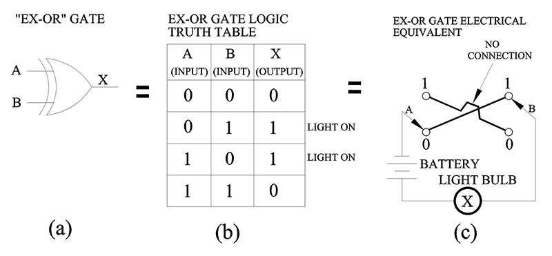
FIGURE 19.
The circuit will be complete (light ON) when switch B is in the 0 position and switch A is in the 1 position. At no time will the light come ON if switch A or switch B are in the same position (1, 1 or 0, 0).
Here’s another way to say it: Either 1 or 0, but not both. Let’s now discuss EX-NOR gates.
The EX-NOR Gate
As you can see in Figure 20c, the light will only turn ON when switch A and switch B are both in either the 1 position or the 0 position.
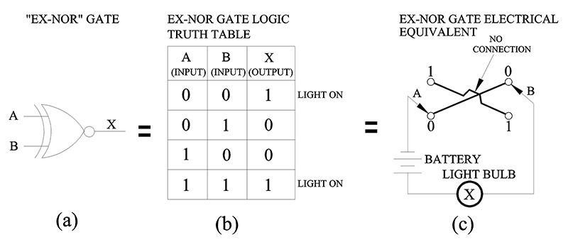
FIGURE 20.
In other words, you have an output (light ON) when ‘both’ switch A and switch B are in the same position, but not when A and B are either 1, 0 or 0, 1.
You can say it like this: both but not either or.
The EX-OR and the EX-NOR gates are used extensively in digital circuits. One application of the EX-NOR — used quite frequently in communications — is to verify that two binary numbers are equal.
Remember, we can change binary numbers into decimal numbers, and through the use of EX-NOR gates compare two decimal numbers by comparing their binary equivalent.
For example, if we needed to compare two binary numbers like 10 and 01 to verify that they are equal, we could use the EX-NOR gate circuit in Figure 21.
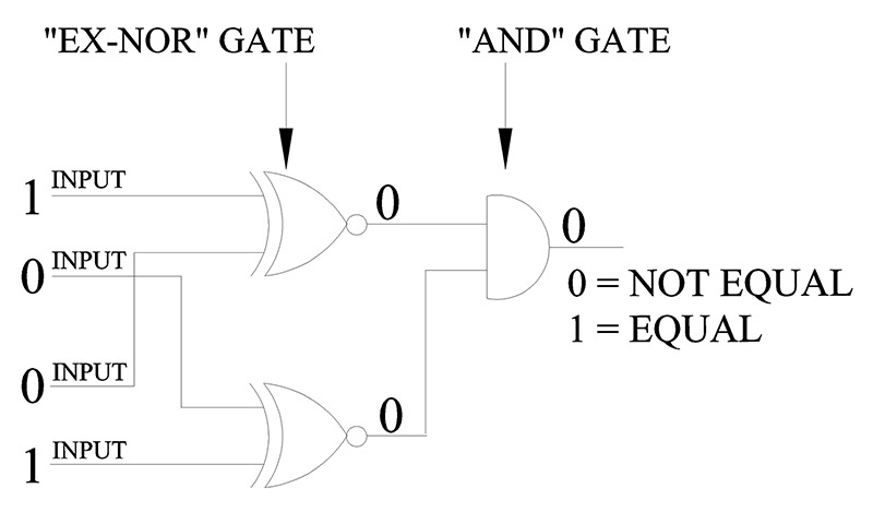
FIGURE 21.
Binary 1, 0 and 0, 1 presented to the inputs of both EX-NOR gates produces a 0 at the output of the AND gate. Therefore, 1, 0 and 0, 1 are not equal binary numbers.
Now, try 1, 0 and 1, 0 at the inputs of both EX-NOR gates. The output of the AND gate will equal a 1, thereby signaling that both binary numbers are equal.
Well, that about wraps it up. I hope you enjoyed learning about the digital world. NV