In a previous article, I developed microcontroller-based hardware and software to control a matrix of 8x8 RGB LEDs. I thought since I still had that hardware laying around, I would use it as a test bed for experimenting with Bluetooth. I had never done anything with Bluetooth before, so I thought it was about time I did.
As you may know, Bluetooth is a standard for the short-range wireless interconnection used in cell phones, computers, and other electronic devices. According to Wikipedia, “It was originally conceived as a wireless alternative to RS-232 data cables.” Of course, today, Bluetooth is used for many purposes, including:
- Hands-free control and use of cell phones.
- Streaming of music for the home, in cars, and even for wireless headphones.
- Streaming of data for file transfers between phones and PCs, and PC to PC.
- For wireless keyboards, mice, and printers.
- For wireless tethering, where “tethering” is the act of sharing a device’s network connection with another device. Most tethering is done via Wi-Fi, but it can also be done with Bluetooth. An advantage of Bluetooth tethering is that it requires much less power than the equivalent Wi-Fi connection.
- And yes, streaming of serial data as an alternative to RS-232 cables.
It is this last purpose that we will be experimenting with in this article.
Abbreviated Bluetooth History
In the early 1990s, a group of engineers at the Swedish company, Ericsson developed the technology that would later be called Bluetooth. The name came from a Danish king who in English is called Harold Bluetooth. Harold united warring factions in his kingdom, just as Bluetooth technology united technology companies in their pursuit of a short-range data communication standard. No one company owns the Bluetooth technology. A Special Interest Group (SIG) of technology companies work together to maintain, extend, and promote Bluetooth. As mentioned, the original intent of Bluetooth was for the replacement of RS-232 cables, but we all know Bluetooth is much more than this.
The original Bluetooth technology is today referred to as classic Bluetooth because of the arrival in 2011 of Bluetooth LE, or Bluetooth Low Energy (BLE). BLE shares many of the same attributes of classic Bluetooth, but is targeted for the type of applications that require extreme low energy usage. In fact, energy so low that a coin battery like a CR-2032 could power a BLE device for five to 10 years.
Classic Bluetooth was designed to continuously stream data, whereas BLE was designed for periodic or episodic data transfer as would be required for remotely located sensors, for example.
A downside of BLE is that it only supports data rates up to around 100 Kbps whereas classic Bluetooth devices can communicate up to 2 Mbps. The new Bluetooth 4.2 revision blurs the lines between classic and low energy Bluetooth even further.
Bluetooth Usage
Bluetooth (BT) devices must go through the process of “pairing” before they can be used together. Not all BT devices will pair together, however. For example, it wouldn’t make sense to connect a BT mouse to a BT headset, although you should be able to pair a BT headset to a BT phone, or a BT mouse to a BT enabled computer.
Each BT device has one or more use “profiles” which describe the types of services they can provide. Devices that are meant to pair together share the same profile. A current iPhone, for example, has seven different BT profiles but curiously lacks the SPP (or Serial Port Profile) we require for our use here. The SPP defines how to set up virtual serial ports and connect two BT enabled devices. Since it has been determined that two BT devices are compatible for connection, a passkey will be required to complete the pairing. Passkeys are generally simple numeric strings like 0000 or 1234. The Bluetooth module used for our experiments uses 1234 for its passkey, though this can be changed for security reasons. Yes, I was quite surprised when I found out that I couldn’t use my iPad for these experiments because it doesn’t support the SPP profile. Luckily, my Nexus 7 Android tablet does.
Bluetooth Connected Hardware
As I mentioned, I wanted to use the 8x8 RGB LED matrix hardware I developed previously for my Bluetooth experiments. As you may recall, this hardware used a Teensy 3.1 microcontroller (from pjrc.com) to control an LED matrix using multiplexing. My thought was I would get an inexpensive Bluetooth module and connect it to the Teensy, then use my Nexus 7 tablet to control things. This actually worked out to be much easier than expected.
Since I was going to use Bluetooth as “a replacement for an RS-232 cable,” I had to choose a Bluetooth module that could do so. Looking around on the Internet, I came across the HC-05 serial Bluetooth module (Figure 1).
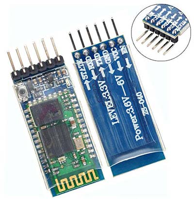
FIGURE 1. The HC-05 serial Bluetooth module.
I subsequently got one for $8 (with free shipping) on eBay. The HC-05 module is capable of being a Bluetooth master or a Bluetooth client; we will only be using it as a client. Only four connections are required to use the HC-05 module in its simplest configuration, with power and ground being two of them. The two remaining signals — RXD (receive data) and TXD (transmit data) — are connected to the Teensy 3.1 microcontroller as shown in the schematic in Figure 2. The TXD signal from the HC-05 is connected to the Teensy’s RX1 signal (pin 0), and the HC-05’s RXD signal is connected to the Teensy’s TX1 (pin 1). The other HC-05 pins are not required for our use here.
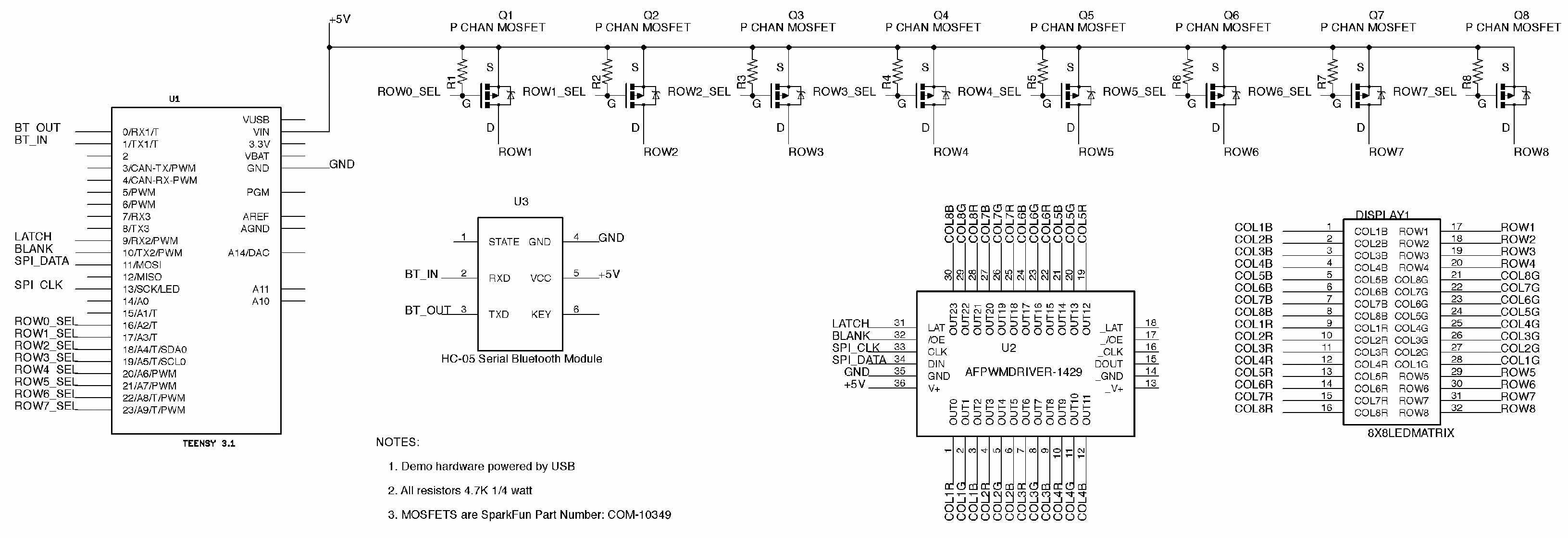
FIGURE 2. Schematic shows connection between a HC-05 serial Bluetooth module and the microcontroller hardware developed in a previous article.
A red LED will begin blinking as soon as power is applied to the HC-05 module. This indicates the module is operational, but not yet paired with another Bluetooth device. NOTE: We will be using the HC-05 with its default configuration. If you are interested in changing its configuration, please consult the following: www.instructables.com/id/Modify-The-HC-05-Bluetooth-Module-Defaults-Using-A/?ALLSTEPS.
Software
There are two parts to the software that need to be discussed: the software on the device we will be using to control the LED matrix; and the software which will run in the Teensy 3.1 that receives commands from the controlling device and executes them.
If you go to the Google Play app store, you can find many apps that support the Bluetooth SPP profile. There are too many to list here of both the free and paid varieties. The app I decided to install on my Nexus 7 is a freebie called “Bluetooth SPP Tools Pro” (https://m.apkpure.com/bluetooth-spp-tools-pro/mobi.dzs.android.BLE_SPP_PRO) which was written by a fellow named Jerry Li. This app is more than capable of controlling the LED matrix remotely.
When first started, this app will scan for any Bluetooth devices in the area and (with our hardware connected and running) it will find the HC-05 device. The first time the HC-05 is detected, you will have to enter the “1234” passkey to complete pairing. If you look at the flashing red LED on the HC-05 module, you will see that the cadence of the flashing changes when the device is paired.
On the screen presented after pairing, you select the mode you wish to use for communication with a remote BT device. I chose to use the Keyboard mode which provides an array of 12 buttons that are configured to send BT commands when clicked. I configured the buttons as shown in Table 1 (the top line of text is the button label/name and the bottom line is the command string that will be sent when the button is clicked).
Mood Light
mood@ |
Random Patterns
rand@ |
Sequential Patterns
seq@ |
Off
off@ |
Speed
speed@ |
Off
off@ |
Hue
hue@ |
Saturation
sat@
|
ValueOK
val@ |
Message 1
msg This is a test message @ |
Message 2
msg Hello Nuts and Volts @ |
Message 3
msg Hello World @ |
TABLE 1.
The buttons are configured by clicking the three vertical dots at the top right of the window and then selecting the Button set menu item. Then, when you click a button, you get a screen asking for the BTN Name (which is the top line above) and BTN Down into which you input the bottom line. When you are finished configuring the buttons, click the dots again, but this time select Button set complete. You should then click Save2File to save your configuration.
Okay, so what do these button commands do? When you click a named button, the string configured for the button is sent wirelessly to the HC-05 module which, in turn, sends it serially to the Teensy 3.1 microcontroller. Code in the Teensy parses the received message string and reacts accordingly. Table 2 describes the effect of each button click.
| Mood Light |
This mode makes the LED matrix function like a mood light. It displays a constant color; the hue, saturation, and value of which can be set with other buttons. If you feel orange in the early evening, you can set the appropriate color for the mood light. |
| Random Patterns |
There are 12 colorful and lively lighting patterns coded into the Teensy software. By clicking this button, these patterns are selected randomly and run for a set period of time until the next pattern is randomly selected. |
| Sequential Patterns |
Clicking this button causes the 12 patterns to be run sequentially. |
| Off |
Clicking this button causes the LED matrix to go off. Clicking any of the top three buttons or the message buttons will cause it to come back on. |
| Speed |
This button controls the speed of the lighting patterns in Sequential Pattern mode. Clicking this button repeatedly causes the speed to increase to maximum, and then return to minimum speed and begin increasing again. Speed is picked randomly in the Random Pattern mode. |
| Off |
I didn’t have any other functions I wanted to implement, so this button also turns the LED matrix off. |
| Hue |
This button changes the hue while in the Mood Light mode. Clicking this button moves the mood light color across the visible spectrum and then starts over again. |
| Saturation |
This button changes the saturation of the LED matrix’s color while in Mood Light mode. Colors with high saturation are pure. As saturation is lowered, the color tends towards white. Like many of the other buttons, the saturation value increases to a maximum, and then resets to minimum and rises again. |
| Value |
This button changes the value of the LED matrix’s color while in Mood Light mode. Colors with a high value are bright, while colors with a low value tend towards black. Like many of the other buttons, value increases to a maximum, and then resets to minimum and rises again. |
| Message 1 |
Pressing this button causes whatever message configured for the button to be displayed on the LED matrix in a scrolling manner using a white font. |
| Message 2 |
Pressing this button causes whatever message configured for the button to be displayed on the LED matrix. |
| Message 3 |
Pressing this button causes whatever message configured for the button to be displayed on the LED matrix. |
TABLE 2.
The software running in the Teensy controller is rather complex and will need to be studied to be understood. The first thing to note is that the BT data from the HC-05 is received on the Teensy’s serial 1 port. I used the SerialEvent library (see https://github.com/duff2013/SerialEvent) to handle this data because it runs completely in the background and only calls the btDataReceived function in the code when string data with the @ delimiter is received. This means the Teensy is fully available for running the patterns and will only be interrupted when BT data is received and in need of processing.
The Teensy code is written as a series of state machines so that the display patterns can run at their full rate while constantly checking for the arrival of BT data. The loop() function in the sketch is looping many times a second, running the top level state machine which, in turn, calls other lower level state machines. This design approach allows the display patterns to be active and lively while still allowing the Bluetooth user interface to be very responsive. Again, study the code if you want to understand it or just use the code as-is and enjoy it. Your choice. To program the Teensy 3.1 controller for this project, you will need to have the Teensyduino environment installed on your development computer.
See http://pjrc.com/teensy/td_download.html for how this is done. You will also need to make sure your Arduino IDE (integrated development environment) is version 1.0.5 or newer.
The code for this project is in the zip file at the end of this article in the downloads. This file should be unzipped and the SerialEvent directory and all of its contents should be moved to your Arduino libraries directory. The BTLEDMatrix8x8 directory from the zip file should be moved into your Arduino project directory. Your Arduino IDE will need to be restarted to see the new library. Once that is done, open the Arduino IDE and using the File/Sketchbook menu selection to navigate to the BTLEDMatrix8x8 sketch. Load it, compile it, and download it to your Teensy controller.
Once operational, pair the HC-05 module on the LED matrix with your BT device, and you will be ready to go.
The Crystal Palace
As I finished writing the software for this article, I was faced with a quandary. I had the LED matrix being successfully controlled via Bluetooth and I was really quite pleased with the result. I could run some very interesting and colorful patterns; I could use the device as a mood light; and I could even display scrolling text messages. What was I to do? Tear down the breadboard I had just finished building to scavenge the parts to use elsewhere, or should I try and figure out a use for the finished product. I, of course, chose the latter.
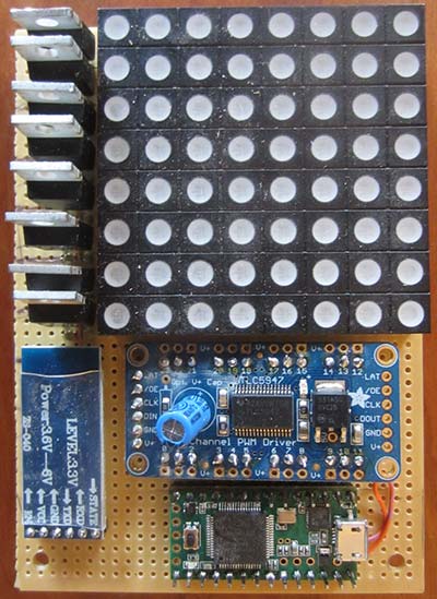
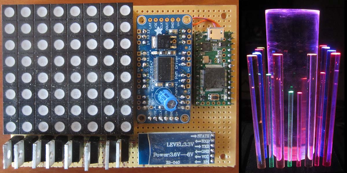
FIGURE 3. The LED matrix hardware with the addition of the HC-05 serial Bluetooth module.
I started thinking about fiber optic displays and how light from a source would travel up a piece of fiber optics and would shine out the other end. I had some clear acrylic rod in the garage, so I took a short piece, sanded its ends to diffuse the light, and placed it vertically on the 8x8 RGB LED matrix. I was pleased to see the light provided by the RGB LED under the rod would shine up through it and brightly illuminate the end, while the rod itself would take on the color very subtly. This really got my juices flowing.
I could mount the LED matrix horizontally and use it as a light source for a group of acrylic rods positioned vertically over it. In other words, the rods would sit directly on the LED matrix.
Next, I needed to determine the arrangement of the rods over the LED matrix. My first thought was one rod for each LED. I could use one diameter of rod of all the same length, or I could vary the lengths to give some up and down motion to the light. I liked the idea of varying the rod length but the uniformity of all the same rod diameters didn’t appeal to me.
In the end, I decided to use a large diameter rod in the center of the display (conveying and mixing the light from many LEDs), and use two different sizes of rods around the perimeter of the LED matrix. I decided on the one LED to one rod relationship around the perimeter. With this arrangement, I would have light from the display patterns moving in both the X and Y directions across the LED matrix, and I would have light moving up and down in the Z direction as well, because of the varying lengths of acrylic rods. In addition, I would have three different sizes of rod ends, like little glowing discs that would be lit from the LEDs below.
When I finally visualized how this thing might look and how it could be built, I immediately flashed back to a Superman movie and his crystal palace hide-away. Thus, the Crystal Palace is the name I gave to this device. So, off I went to Delvie’s Plastics (delviesplastics.com) and ordered 1/8”, 1/4”, and 1-1/2” acrylic rods. Delvie’s has the best prices for plastic I have seen.
However, because you have to buy the rods in quantity, this can be a kind of expensive purchase. The upside is that I have enough material to build many projects that require acrylic rods.
Next up, I had to figure out how to position the acrylic rods accurately over the LED matrix and support them well enough that they stood vertically. Being a wood worker, I decided to mill a piece of 3/4” hardwood with holes for each rod. This worked out well.
Finally, I built an enclosure for my breadboard out of 1/4” MDF and glued the drilled hard wood support on top, after carefully measuring so that the rods would be positioned accurately over their respective LEDs in the matrix. I also cut a square hole in the side of this enclosure for the USB power cable which connects to the Teensy 3.1 microcontroller to pass through. After gluing up the enclosure and doing some finish sanding to round over edges and remove any traces of glue, I painted the enclosure with black sparkle paint. This turned out to be a crude but effective enclosure (Figure 4).
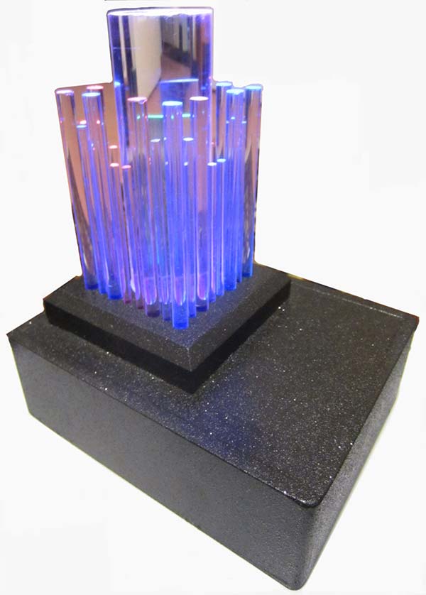
FIGURE 4. The finished Crystal Palace.
You can watch the finished Crystal Palace in operation at www.youtube.com/embed/mtjrkF2MqbM. If I were to build another one of these, I would do some things differently.
First, I would have made the breadboard square and not rectangular by mounting components on both sides of the board. I might even make a PCB (printed circuit board) instead of using point to point wiring next time.
Second, I would probably design the rod support and enclosure in a CAD system and 3D print it for much better positional accuracy.
Finally, I am thinking about making a bigger, better Crystal Palace by using a 32x32 RGB LED matrix like the one I used in my Light Appliance project (see N&V’s October 2014 issue).
Bigger is always better, right? NV
Downloads
Serial Event and BTLED Matrix 8x8, Source Code, Schematics