Recap
In the C theory section of our last episode, we looked at C programming concepts for enums and data structures. In the lab section, we got started with the DS1307 real time clock (RTC) IC. Then, right in the midst of exploring these concepts I stumbled across Fritzing — an open source application that attempts to do for hardware design (electronics computer-aided design) what the Arduino did for software. Fritzing is a very novice-friendly open software package that you can use to design shields for Arduinos. Even though it is still in beta, it has many very interesting and useful features. So, I decided to put our study of time on the shelf and do two workshops on Fritzing, then come back to how C programmers deal with time later.
Fritzing is being developed by the Interaction Design Lab of the University of Applied Sciences Potsdam, Germany. It is open source, so there are contributors from all over the world. You can get more information from www.fritzing.org.
Fritzing
I am constantly reminded about the great variety of skill levels present in readers of my Workshops. Some folks can program circles around me, but wouldn’t know which end of a soldering iron to use if their life depended on it. Others can hand-solder surface-mount parts on PCBs of their own design but can barely use an Internet browser, much less write a program. Most readers are somewhere in between having enough hardware and software knowledge to be dangerous, but still learning both. I’ve been slowly introducing the C programming language software while also applying these concepts to microcontroller hardware projects so that folks from both ends of the spectrum can get some incentive to learn the parts they don’t already know.
This episode will cater a bit to the hardware novice by introducing Fritzing, which can help a beginner get started with hardware design.
First, we will use Fritzing to design a DS1307 RTC circuit we were introduced to in Workshop 48. In this first installment, we will follow Figure 1 to build a circuit on a breadboard that we can use with some Arduino code, then we will convert the breadboard design to a schematic.
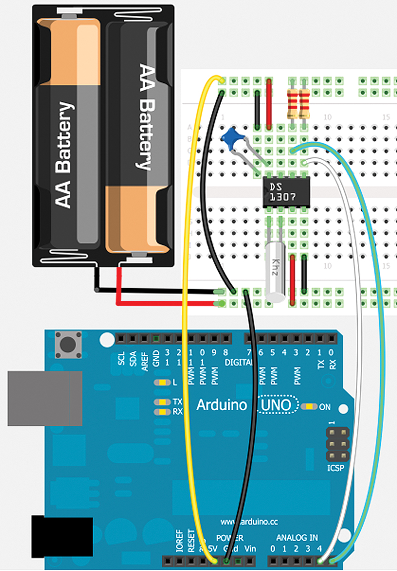
FIGURE 1. Real time clock all wired up.
In Part 2, we will see how to use the breadboard/schematic designs to generate a PCB layout that we can use to have a circuit board fabricated. Essentially, you’ll see the full hardware design cycle from the breadboard prototype to the finished product.
What is Fritzing?
You can get the Fritzing application from www.fritzing.org. They introduce themselves as follows:
Fritzing is an open source initiative to support designers, artists, researchers, and hobbyists to work creatively with interactive electronics. We are creating a software and website in the spirit of processing and Arduino, developing a tool that allows users to document their prototypes, share them with others, teach electronics in a classroom, and to create a PCB layout for professional manufacturing.
I downloaded the 0.74 b April 10, 2012 version and used it in the illustrations here. It is 18.6 MB which isn’t terribly large nowadays, but you’ll probably want a broadband connection to download it. Do note that Fritzing is in beta release and this isn’t even version 1.0 yet; since it is an open source project, it might just stay in beta for a while. The creators are very aware that Fritzing is a work in progress and you should expect some problems, but remember the price is free. If you like this tool and want to see it improved, you could send them a donation at http://fritzing.org/shop/donations.
When you run the program, the first thing you see (shown in Figure 2) — as is so often the case with Microsoft — is a completely useless security warning that — trust me — you can ignore.
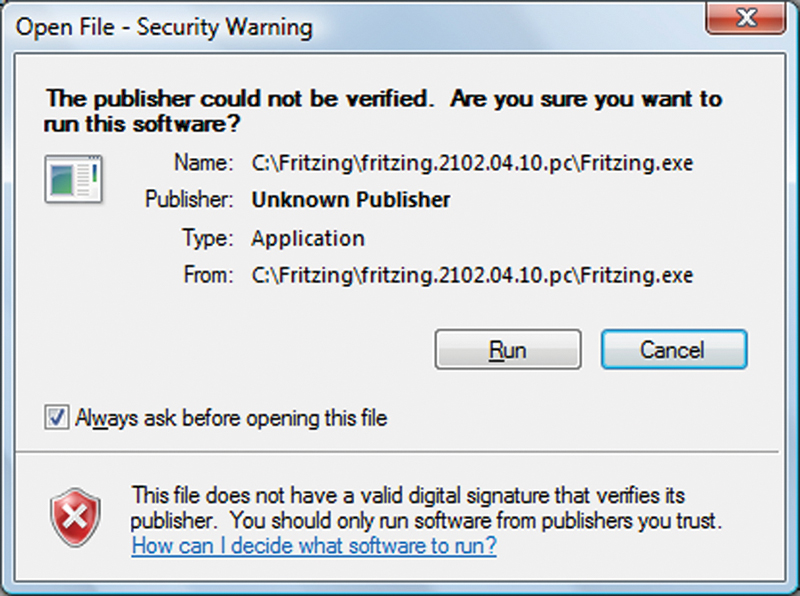
FIGURE 2. Security warning.
After dismissing the stupid security warning, notice the Fritzing splash screen shown in Figure 3.
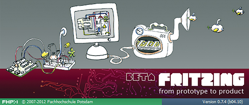
FIGURE 3. Fritzing splash screen.
On the left, you see an Arduino connected to a breadboard; in the middle, you see a computer with the design in Fritzing connected; and then on the right, there’s a replicator that is outputting tiny flying submarines. This cute drawing pretty much covers what the folks at Fritzing think they are about and although they have a long way to go, they at least are making a light-hearted first step in the right direction.
When I first opened Fritzing, it came up in the breadboard view shown in Figure 4.
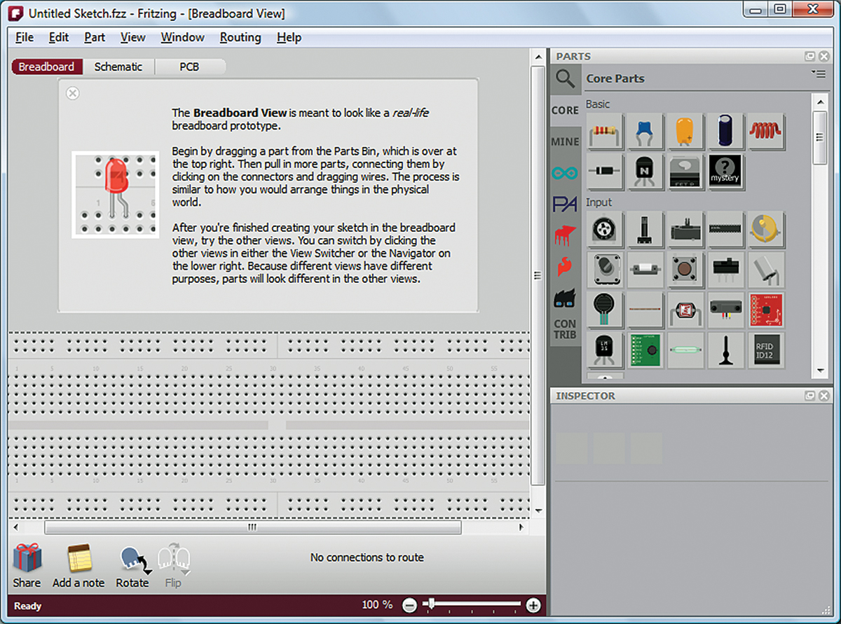
FIGURE 4. Fritzing breadboard view.
Let’s close the breadboard welcome and move the breadboard up and resize the whole window as shown in Figure 5.
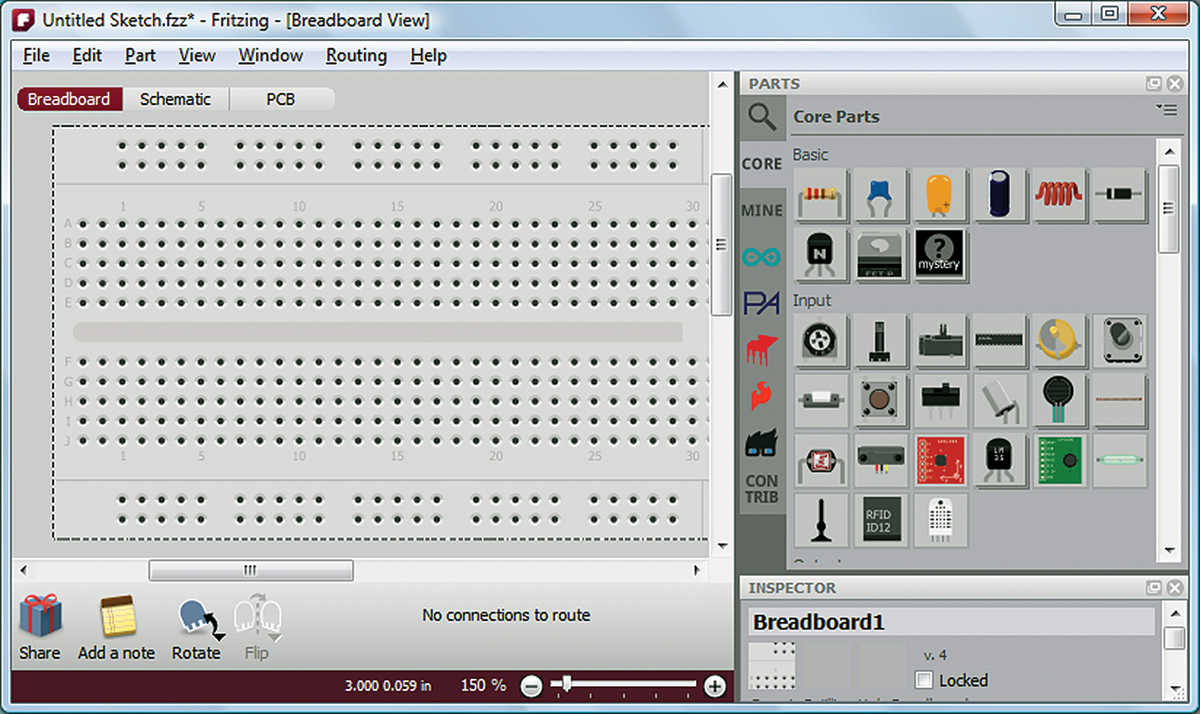
FIGURE 5. Resize.
Now, in the parts window open the core parts and scroll down to the ICs. Hmmm ... they have a DS1302 (as shown in Figure 6), but we are using the DS1307 for our RTC.
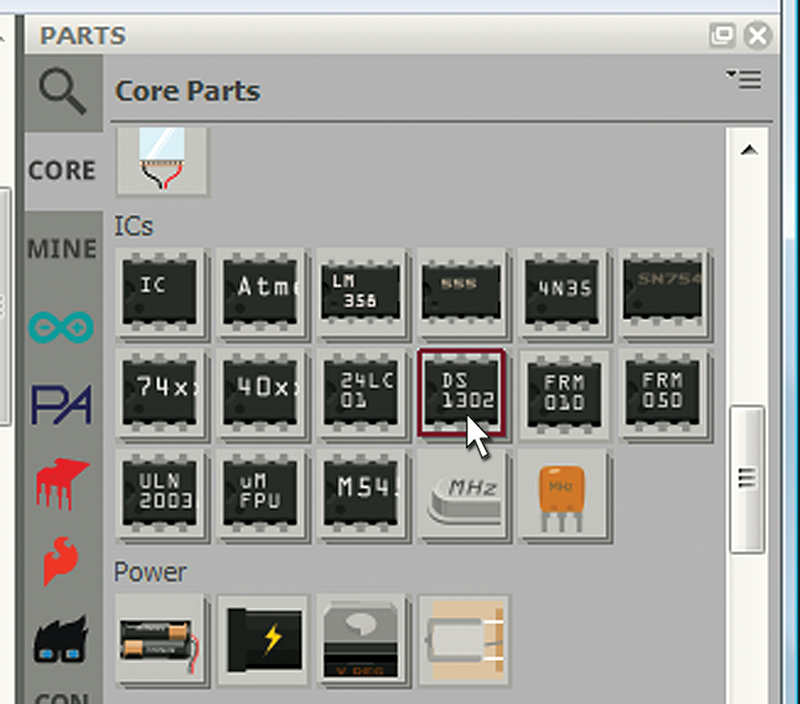
FIGURE 6. Core ICs DS1302.
Do they have the same pinout? I did some Internet searching for the datasheets and discovered the DS1302 and DS1307 aren’t the same. So, let’s see if there is any help for this problem. [NOTE: I found a better way to get the DS1307 and will discuss it later in the article. For now, just think of this section as a generic discussion on how to import a part.] Figure 7 shows the link to Fritzing’s Online Parts Reference.
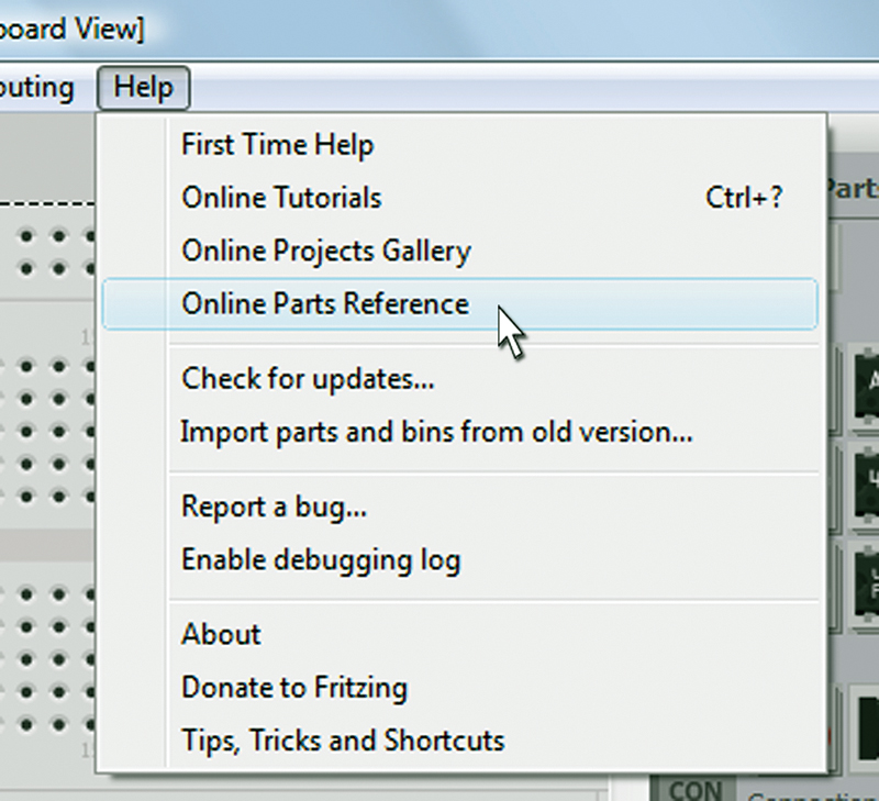
FIGURE 7. Online Parts Reference.
That led to a Fritzing web page that has a link to the Fritzing parts repository that led to the DS1307RTC.fzpz that I downloaded. In Figure 8, I select the import item in the Fritzing Part menu.
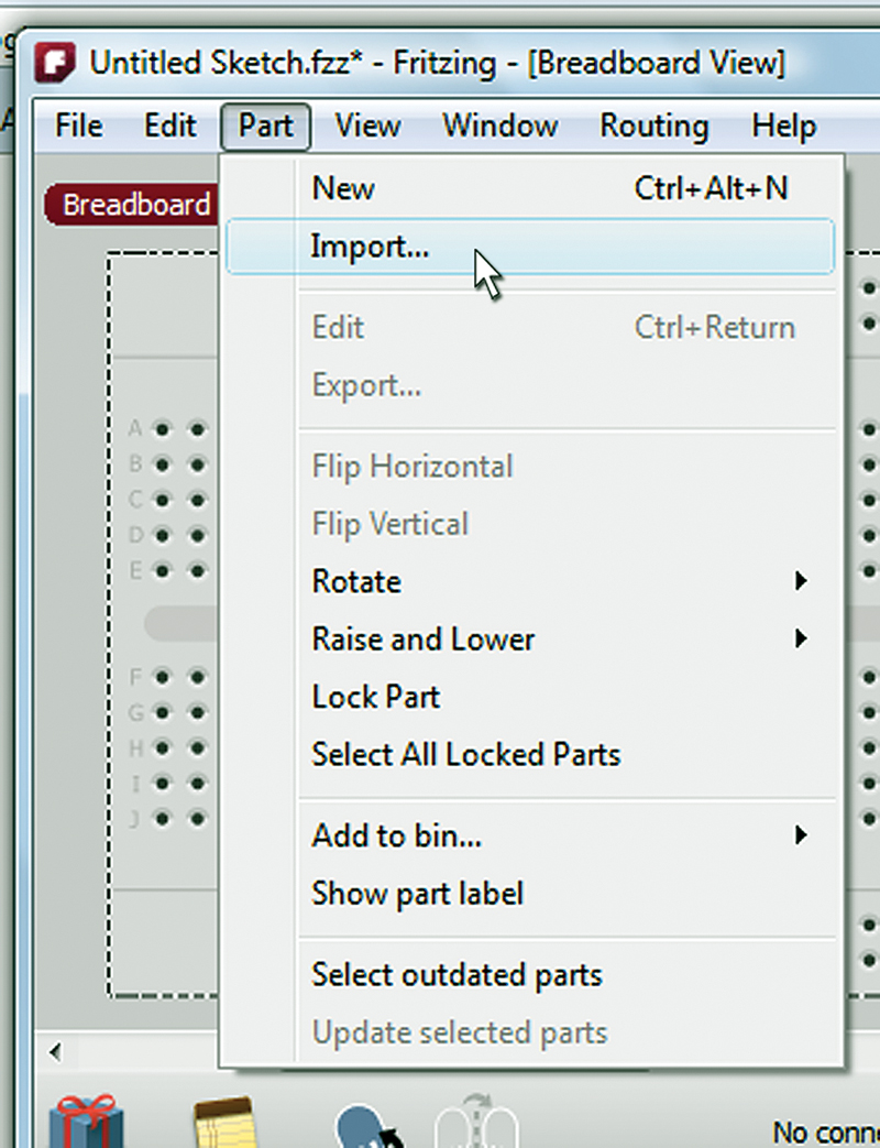
FIGURE 8. Import.
Then, in the directory browser window shown in Figure 9, I select the part to import.
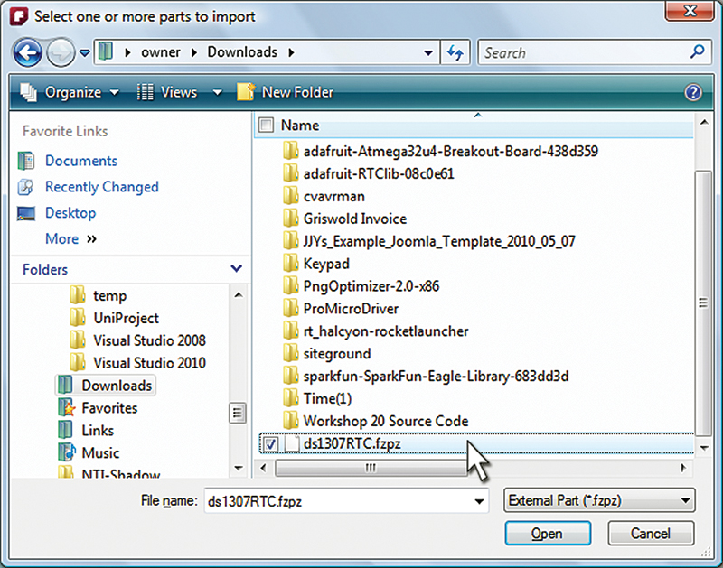
FIGURE 9. Select the part to import.
Next, I searched for the DS1307 using the (magnifying glass denoted) parts search facility shown in Figure 10.
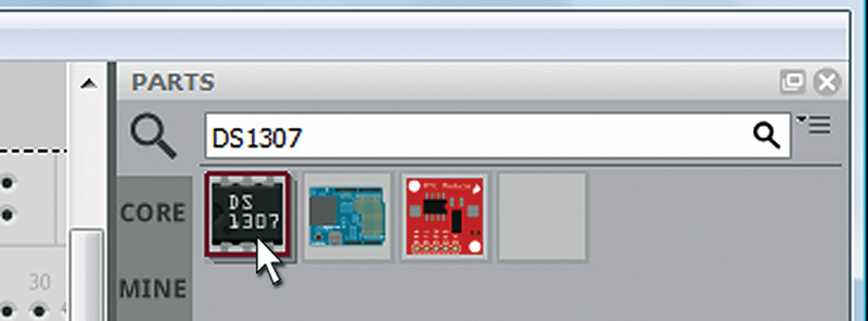
FIGURE 10. Parts search for DS1307.
Then, I clicked on the part and dragged and dropped it on the breadboard as shown in Figure 11.
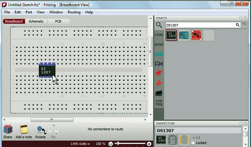
FIGURE 11. Drag it to the breadboard.
Notice how the part locks onto the holes, putting the DS1307 pins into them. When you release the part, the connections are shown in green (see Figure 12).
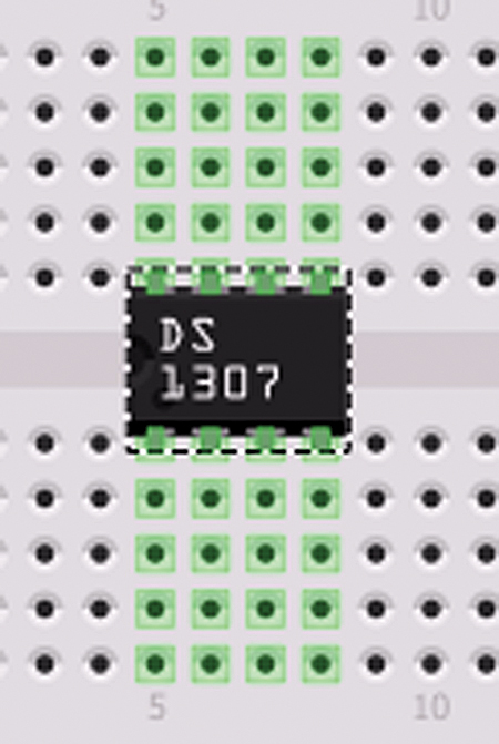
FIGURE 12. Connections shown in green.
What isn’t clearly shown is which pin is pin 1. Figure 13 shows what happens if we let our cursor hover over a pin.
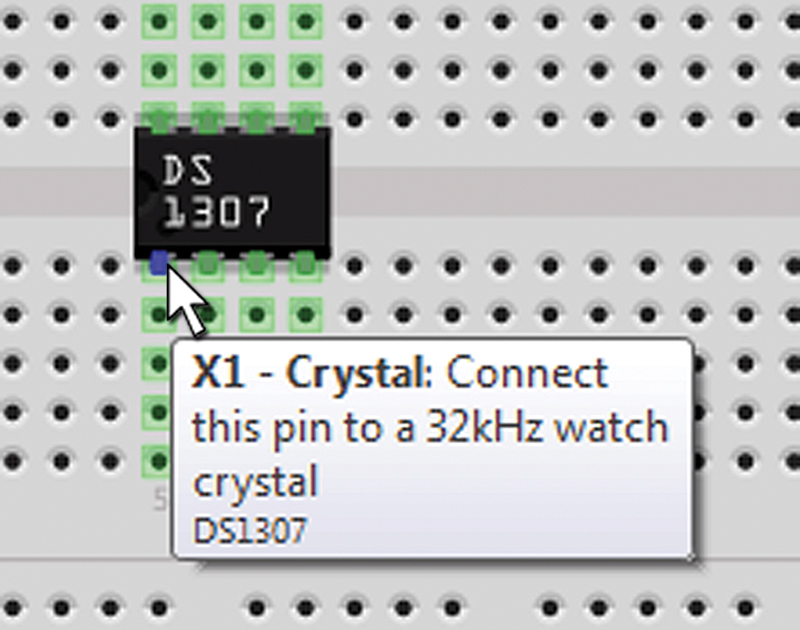
FIGURE 13. Identifying pin numbers.
We see that this is the X1 pin, and the next pin is X2. By referring to Figure 14 which shows an illustration from the DS1307 datasheet, we see that these are pins number 1 and 2.
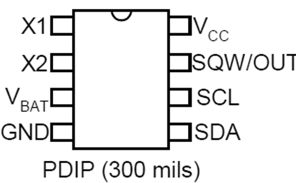
FIGURE 14. DS1307 pins in datasheet.
We can tell this because the drawing has a circle divot on the IC to indicate the end with pin 1, and that pin is always on the left in the depicted orientation.
Next, we consult the datasheet illustration of a typical operating circuit (as shown in Figure 15) to decide what other parts are needed and how we will wire them up.
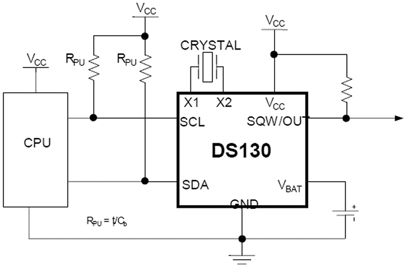
FIGURE 15. Typical operating circuit.
Let’s be honest here. We selected the DS1307 in the first place because there are a bunch of circuits on the Internet that show how other folks have done this design, so we will be highly influenced by those observations. [One thing to note is that I used a 0.1 µF bypass capacitor that isn’t shown in a typical circuit. I do this because I’ve had enough experience to know that these help prevent digital glitches. Although we might get by without it, they are cheap and have proven necessary often enough in the past that I just throw one in for every digital IC and sleep better.]
So, based on Figure 15 and the datasheet specifying the crystal, the next thing I wanted was a 32.768 kHz watch crystal to use on the breadboard. So, I imported “CRYSTAL – kHz.fzpz” as before and it almost killed my Fritzing session! I searched a bit further and found a more recent version of that file and it worked just fine. Lesson: You might have to mess around a bit to find these parts, and they might not work. (This is just one of the joys of open source design.)
Now, notice in Figure 16 that the part selector box shows ‘MHz’ which probably means the author of this part reused an image (since the price is right, we won’t fault him).
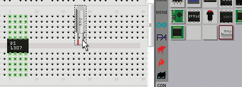
FIGURE 16. Select and move the crystal.
The part itself looks like the watch crystal we will be using, so we drag it over to the DS1307 and drop it onto pins 1 and 2. Unfortunately it covers the IC and blocks most of the breadboard connections for pins 7 and 8, so let’s flip the part around 180º as shown in Figure 17.
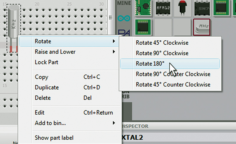
FIGURE 17. Rotate the crystal.
The Inspector Window
Boy howdy! Am I embarrassed! I was writing this tutorial on the fly while learning to use Fritzing, and after all that rigamarole about how to import a DS1307 since they only have a DS1302, I find I was wrong, wrong, wrong! The DS1302 part has a DS1307 variant that you can select in the Inspector window. So, rather than rewrite the whole article and since knowing how to import files is a good thing, I’ll just leave all this import stuff in and tell you how to do it the right way.
You select a DS1302 from the parts bin and drop it on the breadboard, then (as shown in Figure 18a) you open the ‘variant’ dropbox and click on DS1307.
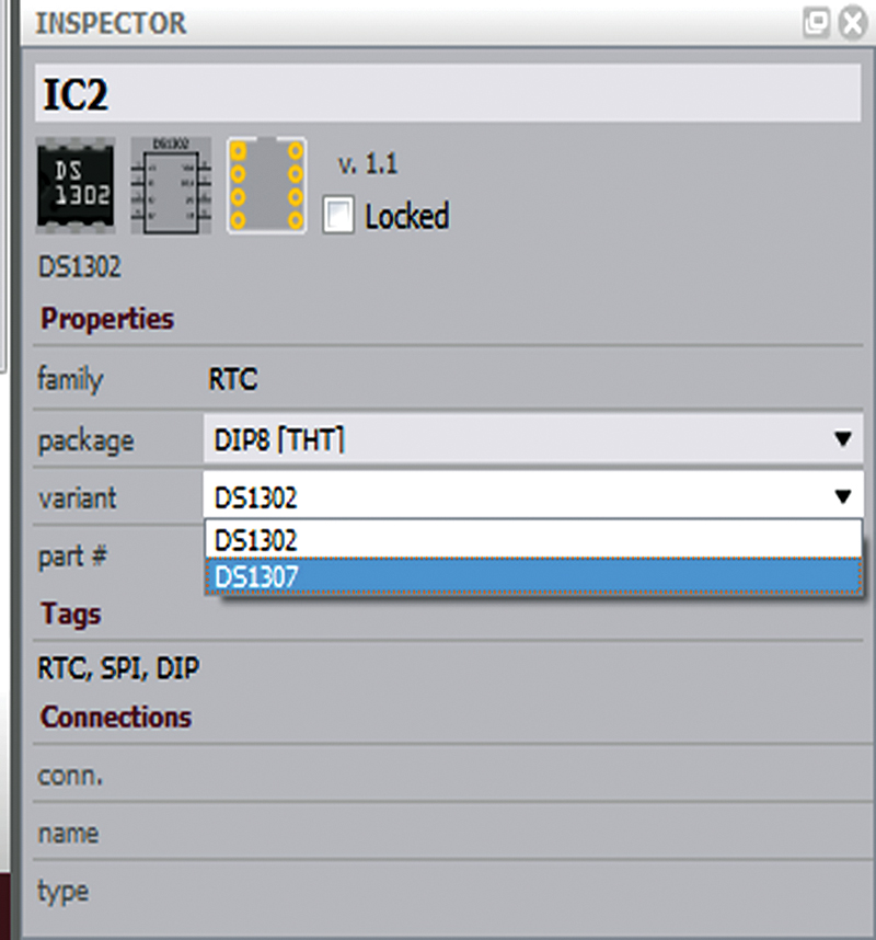
FIGURE 18A. Inspector window.
Voilà! You have the correct part. We repeat this pattern when we add the resistors (shown in Figure 18b rotated as with the crystal).
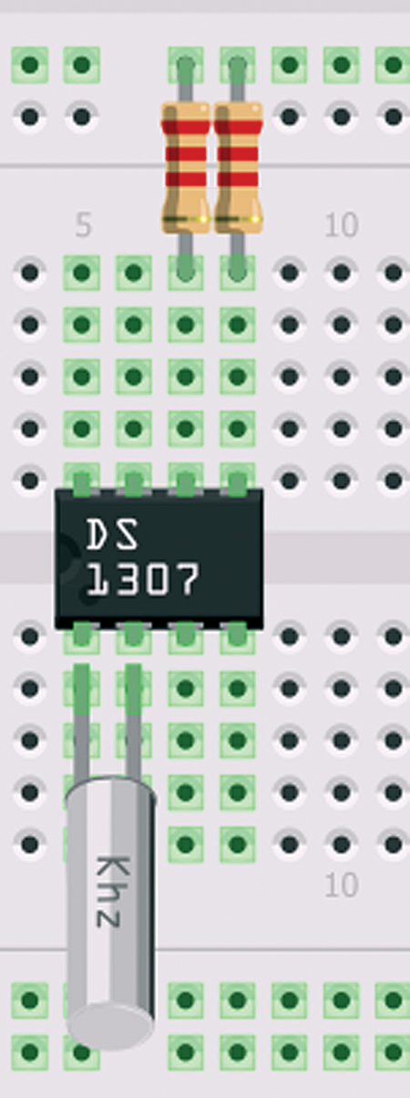
FIGURE 18B. Add resistors.
The default is 220 ohms, but you can click on the resistance dropbox in the resistor’s Inspector window and select 2.2K, which changes both the value and the color bands.
If an exact part you want to use is not in the parts bin, you may find a similar part can be modified in the Inspector window to match your needs. If the exact part you need just isn’t available, the folks at Fritzing will create a part for you (for a fee, of course).
Back to the Breadboard
We connected the resistors between pins 7 and 8, the upper breadboard row that we will need to connect to VCC, but let’s get all the parts down before we flip the power switch.
We add a 0.1 µF bypass capacitor as shown in Figure 19.
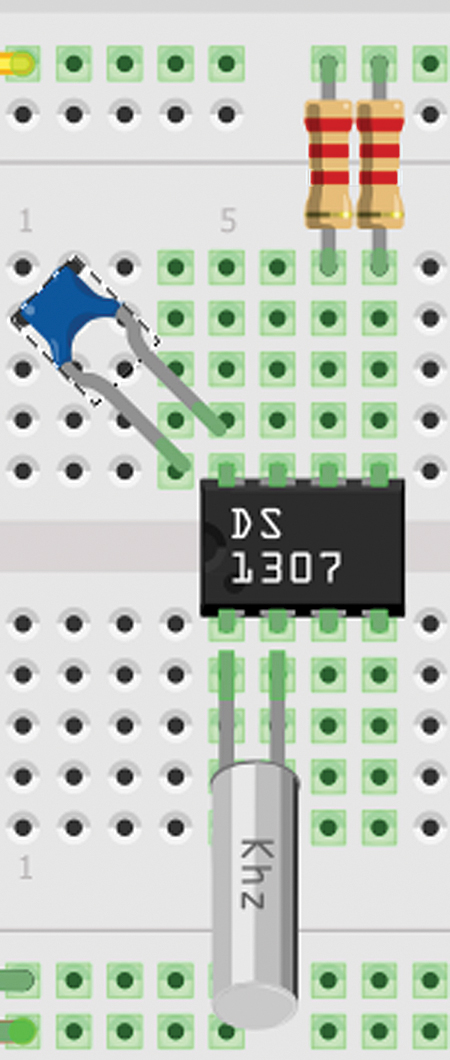
FIGURE 19. Add a bypass capacitor.
Note that I chose to rotate the part by 45º so that it wouldn’t block the pins that we will need to attach to VCC and GND.
Now that we have all the parts on the board, we will want to add the wires. Before we do that, we will want to add an Arduino that will be reading the date and time from the DS1307, and will be providing the main power. We will also want to add a three volt battery for backup. While we almost certainly would be using a coin cell for the backup battery in a ‘real’ design, for this drawing let’s just use a battery box with two AA batteries since we have one at hand. [Okay, I have one at hand.] NOTE: DON’T BE TEMPTED TO SOLDER WIRES TO A COIN CELL BATTERY TO USE WITH A BREADBOARD — IT MIGHT BLOW UP!
Next, you will want to zoom out to make room for an Arduino and a battery box that you can find among the parts. Drag them and drop them into the breadboard window as shown in Figure 20.
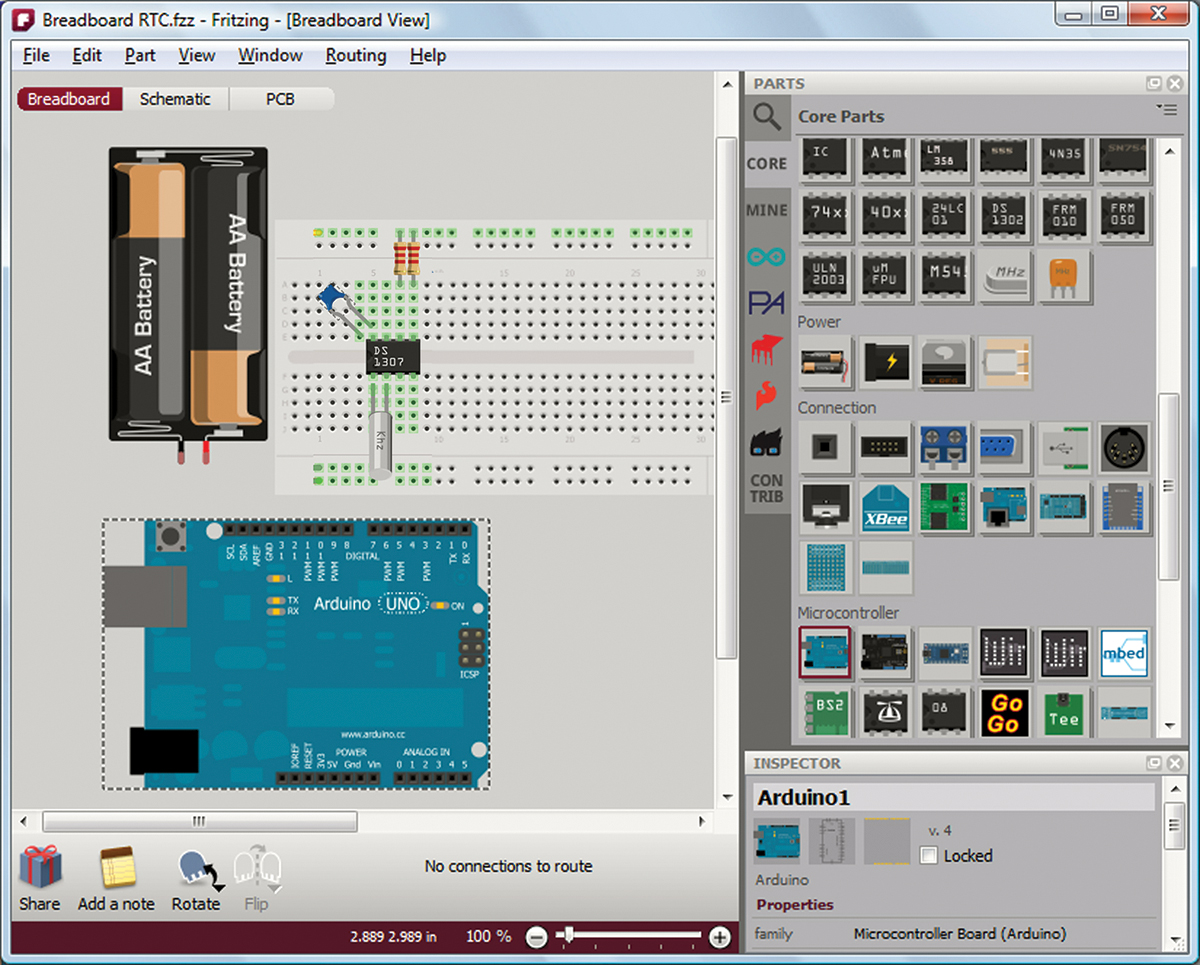
FIGURE 20. Add the Arduino and the battery box.
Now we have all the parts, so let’s wire it up. You’ll want to refer back to Figure 15 for this. First, let’s do the power and ground wiring. Note that there are two power sources; according to the datasheet, we want +5 volts on pin 8 and +3 volts on pin 3 (for our backup supply). In Figures 21 and 22, we see that we can left-click the cursor on a part’s connector, drag the wire to the connector we want to attach to, and then release the wire.
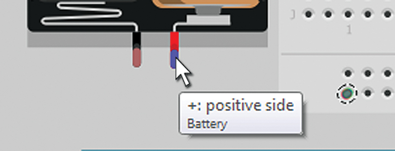
FIGURE 21. Start wire.
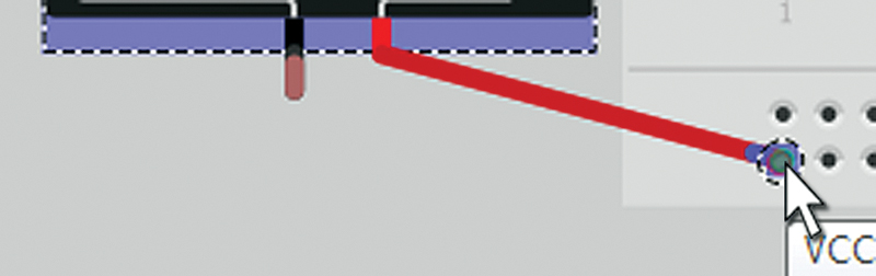
FIGURE 22. End wire.
Since this forms a straight line that might get in the way of seeing all the wires on a board, we add a bend (as shown in Figures 23 and 24) by first right-clicking on the wire to get the ‘add bendpoint’ indication and then left-clicking the cursor to grab the bend so that we can move it to where we want it.
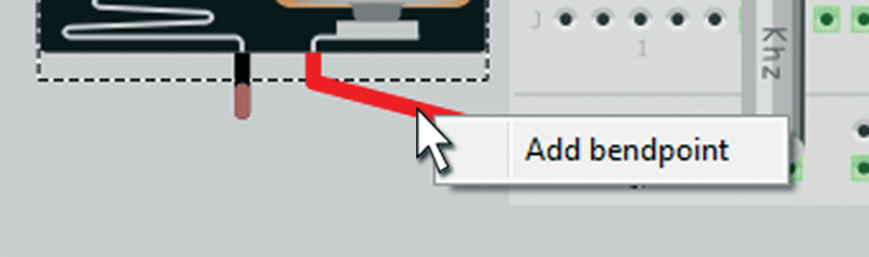
FIGURE 23. Start bend.
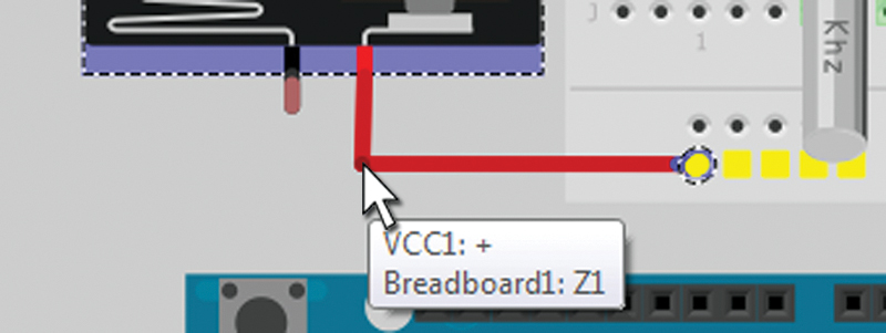
FIGURE 24. End bend.
Now that you see how to add a wire, you should make all the connections shown in Figure 1. When I ran the +5 volts up to the top of the breadboard, I was given a blue wire that wasn’t very visible over the Arduino, so I right-clicked on it and got the option to change the wire color to yellow. I then changed the Arduino ground wire color from blue to black. I suggest you change all the wire colors to match the illustration in Figure 1, just to keep things simple.
Right angle bends are fine, but when you build this with real wires you are going to have a lot of curves. Fritzing helps illustrate this by allowing you to add curved bends. Just hold down the CTRL key when you left-click on a wire, and you’ll get a rounded bend. This is something you need to fool around with a bit since describing it isn’t as useful as actually watching what happens. You should get something like the curves shown in Figure 1.
Now we know how last episode’s Arduino/DS1307 RTC on a breadboard was generated.
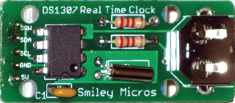
FIGURE 25. The DS1307RTC kit.
We are now ready to use this design in Fritzing to generate a schematic and layout for a printed circuit board — which we will do next time in Part 2.
Another Real Time Clock Option
This two-part Fritzing tutorial shows you how to design and build your own DS1307-based real time clock. If you just want one to play with, you can purchase the DS1307RTC kit (which contains all the parts you’ll need) from the Nuts & Volts Webstore. See you next time. NV