For quite a while now, we have sought the ultimate add-on interface board to enhance some Raspberry Pi (RasPi for short) projects we want to pursue, including a mobile webcam and a wireless sensor network. For such projects to work, it's essential that our RasPi add-on meet several particular criteria.
For starters, its microcontroller must be easily programmable. This is important because we need to be able to offload the RasPi from the more mundane control/monitoring functions, leaving it free to do vision processing and/or web control.
The add-on would also need a healthy mix of I/O — both digital and analog interfaces — and an expansion port capable of addressing custom electronics. The adapter shouldn't be larger than the RasPi to make packaging easy and it would also lend itself to better mechanical stability when mounted to the RasPi (to handle vibrations).
Another necessary feature is easy access to the RasPi general-purpose input/output (GPIO), so as not to block onboard cable connectors (that is, the camera). Finally, in the interest of green design, the add-on should cycle and control power to the RasPi remotely using a real time clock calendar (RTCC) to facilitate shut-down and/or power-up.
Several electronic add-on adapters that are commercially available might have provided our solution. We had considered the top candidates to be the Gertboard and the aLaMode (both processor-based add-ons), but we had to rule out the Gertboard because of its size. Then, we focused our attention on the aLaMode. It offered both a programmable microcontroller and an Arduino-style expansion interface. Its size is right for the RasPi, and it has fully accessible GPIO. However, because cables must be routed around the board, the RasPi card cable connections are blocked. Another issue with aLaMode is that its Arduino connectors (A0 to A5) can easily touch the bare metal of the RasPi RJ45 which is a potentially dangerous situation in a mobile environment. Finally, aLaMode has no remote control power.
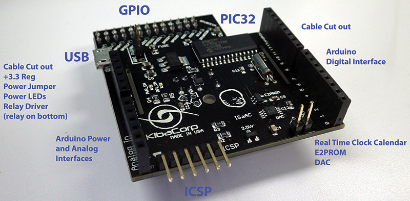
FIGURE 1.
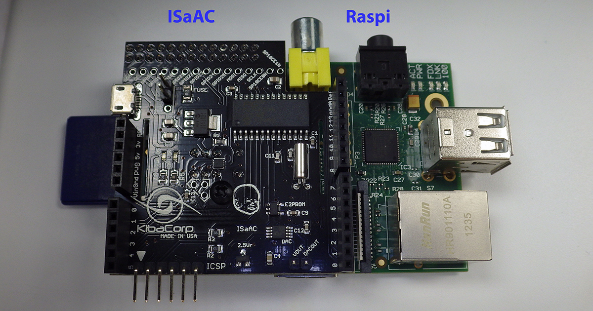
We decided to build our own add-on adapter which we designated the “ISaAC” (Ideal System and Application Circuit) to address all of our criteria directly (see Figure 1 showing ISaAC and Figure 2 showing ISaAC mounted onto the RasPi). Our final ISaAC design resulted in an onboard, relay-based power control to the RasPi, a Microchip 32-bit processor, a DAC for signal generation, EEPROM (for nonvolatile storage access as needed), an Arduino-compliant electronic interface, open slots onboard to pass through a RasPi ribbon connector, and an RTCC for precision timed-based control in a compact SMT package.
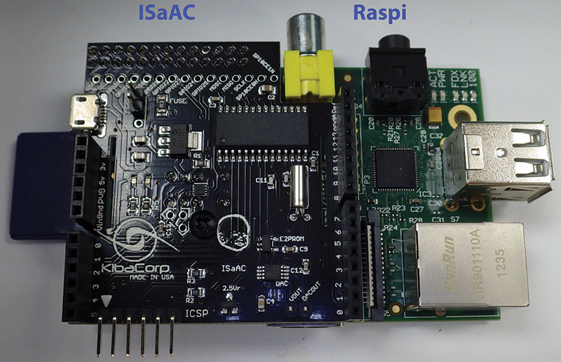
FIGURE 2.
While designing the ISaAC, another thought occurred to us besides hardware. The ISaAC uses a Flash programmable Microchip PIC32. How about developing the ISaAC to contain a pre-programmed environment — one in which all onboard functionally is available through an API (Application Program Interface)? The API would support any custom hardware debugging without the need for developing special test code. It would also facilitate rapid development of any project application software.
We composed the API using an ASCII command/response serial interface, thereby allowing easy direct viewing of any results. The benefit of the serial port is that it allows for available application software (Teraterm, HyperTerminal, and Minicom) that can work with the API directly. Once an API is learned in this way, it can be easily invoked within Python using an ISaAC API library. The ISaAC API (currently 19 commands) is discussed in depth in the Reference Section sidebar, as well as a description of ISaAC Arduino format pins.
Reference Section
| 1.0 — ISaAC Pinout Reference |
| Reference |
Digital I/O Pin |
API Designation |
Function |
| D0 |
0 |
00 |
Programmable digital I/O |
| D1 |
1 |
01 |
Programmable digital I/O |
| D2 |
2 |
02 |
Programmable digital I/O |
| D8 |
8 |
08 |
Programmable digital I/O |
| D9 |
9 |
09 |
Programmable digital I/O or PWM |
| D10 |
10 |
10 |
Programmable digital I/O or PWM |
| D11 |
11 |
11 |
Programmable digital I/O |
| D12 |
12 |
12 |
Programmable digital I/O |
| D13 |
13 |
13 |
Programmable digital I/O |
| A0 |
0 |
14 |
Analog In 10-bit ADC/Programmable Digital I/O |
| A1 |
1 |
15 |
Analog In 10-bit ADC/Programmable Digital I/O |
| A2 |
2 |
16 |
Analog In 10-bit ADC/Programmable Digital I/O |
| A3 |
3 |
17 |
Analog In 10-bit ADC/Programmable Digital I/O |
| A4 |
4 |
|
I2C Bus Data |
| A5 |
5 |
|
I2C Bus Clock |
| 2.0 — ISaAC API Reference |
| API Commands |
Function |
| ? |
Query state of digital input pin |
| A |
Set pin to analog input/read |
| CR |
Read RTCC clock |
| CS |
Set RTCC clock |
| D |
Output to DAC |
| ER |
Single EEPROM read |
| EW |
Single EEPROM write |
| H |
Set output pin high |
| I |
Configure pin for digital intput |
| L |
Set output pin low |
| M |
Help menu |
| O |
Configure pin for digital output |
| P |
Set pin to PWM output |
| Q |
Build script |
| T |
Set alarm |
| U |
Pi power cycle on alarm |
| V |
View EEPROM |
| X |
Execute script |
| Z |
Z Precision pulse |
ISaAC communicates to the Pi over the GPIO serial port at 192008N1. API commands are ASCII upper case characters and are echoed back for easy debugging. Command verification from ISaAC is simply ‘A’ (acknowledge) or ‘N’ (not acknowledge). There are 19 unique API commands.
The ISaAC board comes fully assembled, pre-programmed, and tested. It supplies power to the RasPi using a micro USB. Its +5V power-only interface helps minimize the number of USB cables required for the RasPi. Power to the RasPi is through a +5V relay controlled by ISaAC located on the bottom of the ISaAC board.
The default setting for the relay is Power On. Selecting relay power for the RasPi uses an onboard jumper setting. Turning off the relay power requires an API command U — see the ISaAC Technical Reference Manual — which (when used with the RTCC) allows an orderly shutdown and restart of the RasPi. Once powered down, the ISaAC/RasPi current consumption drops considerably.
The ISaAC has a Microchip In-Circuit Serial Program (ICSP) interface that allows reprogramming of the ISaAC Flash to accommodate API revisions.
To assist in using the ISaAC with your DIY experiments and projects, download the technical reference manual (mentioned earlier) available in the downloads at the end of this article. This manual describes the electronics and API operations in detail, the ISaAC Python API library, and the ISaAC API MPLAB X library project (for those who want to familiarize themselves with ISaAC API implementation).
Let’s Get Started
As mentioned, the ISaAC uses the RasPi serial port on the GPIO for API communications. First, we must configure this administrative port so the system software can access it. Once we’ve accomplished this task, we will work with the low level API to test our hardware. RasPi Minicom is a good way to become familiar with the API while testing and debugging hardware before any coding.
Once we are satisfied with proper hardware operation, we will use the Python lganguage and the ISaAC Python Extended API library to develop the application example. We will step you through a process for building a RasPi servo control system. In this example, the servo position is set by changing a potentiometer setting. A blinking LED indicates the program is active.
Installing ISaAC
1. Prepare the RasPi for the ISaAC board. We must reconfigure its serial port (ttyAMA0) because — by default — it is set as the administrative terminal. Open the /boot/cmdline.txt file for editing.
2. Remove the following:
console=ttyAMA0, 115200 kgdboc=ttyAMA0,<br />
115200
3. Save and close the file.
4. Preventing the RasPi from outputting boot information over the serial line is an important step. Otherwise, the serial buffer can get overwhelmed by all the data. This can make it difficult to successfully send commands to the ISaAC initially. Open /etc/inittab for editing.
5. Place a hashtag (#) in front of the following line that reads:
TO:23:respawn:/sbin/getty –L ttyAMA0115200<br />
vt100
6. Use the following command to initiate the RasPi’s shutdown:
sudo shutdown now –h
7. After shutdown, attach the ISaAC board to the RasPi. ISaAC supplies power to the Pi through the GPIO, so only one micro USB is required (the one that connects to ISaAC). Place the jumper on the RPI PWR spot on the ISaAC and attach the micro USB power cable to it.
8. The ISaAC uses a red LED for +3.3V power indication and a blue LED for relay on/off indication. Both boards should power-up now, and these LEDs should be on. Make sure that your RasPi is functioning normally via your method of choice (i.e., SSH or HDMI port).
9. Open Minicom using the following command:
sudo minicom -s
You must request superuser permissions to make changes to the configuration and access the onboard serial port. If you don’t have Minicom installed, type the following command:
sudo apt-get install minicom
10. Now that Minicom is open in configuration mode, choose the serial port setup menu item and then press A to change Serial Device to /dev/ttyAMA0.
11. Press E to adjust the serial port settings. Scroll through the menu with A and B until you find a baud rate of 19200. Ensure the Current: line at the top reads 19200 8N1.
12. Press enter to leave this screen, and press enter again to go to the main menu.
13. Click Save setup as dfl. To make this the default setting, click Exit which will place you into the active Minicom terminal.
Running ISaAC
Here are a few precautions before we proceed:
- If you are breadboarding your circuits with a separate power supply, make sure to link the power supply ground and ISaAC ground pins. For most simple experiments, the ISaAC should be able to supply power to the breadboard.
- For routine purposes, only use the ISaAC board to supply power to the RasPi. If independent cables are used to power the RasPi, remove the RPI PWR jumper and make sure both boards use the same power source. Failure to do so risks permanent damage to both boards.
Testing the Hardware With API
Test 1 — LED
Let’s use a classic “HELLO, WORLD” example to test the API under Minicom.
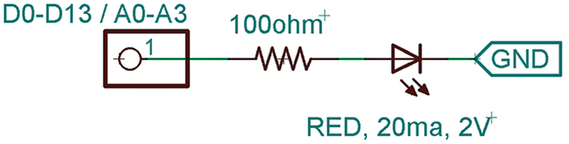
FIGURE 3.
1. Plug in an LED using the appropriate resistor for any of the peripheral pins on the ISaAC (D0-D13 or A0-A3). Refer to the circuit diagram in Figure 3.
2. Open the Minicom terminal as a superuser.
3. Let’s assume we have connected to pin 1 on our ISaAC board. Set the pin to an output by typing O01 into the terminal; you should receive an “A” as a response.
4. Type H01. The light should now turn on (if it hasn’t already). Type L01 and the light will turn off. We set pin 1 to an output with the first command; we set that output to high (on) and then we set it to low (off).
These pins can assume three states: high output, low output, or input (otherwise known as tri-state GPIO). All of the pins on the ISaAC can be commanded in this way. A few of the pins have additional special functions:
- Set pin to output — O, then two digits for pin
- Set pin to high — H, then two digits for pin
- Set pin to low — L, then two digits for pin
Test 2 — ANALOG ADC
Measuring digital states is very useful, but having the ability to measure analog signals adds another dimension of utility. The ISaAC has four pins that have 10-bit analog-to-digital conversion (ADC). These pins are labeled A0 to A3. An example circuit can be created with a thumb potentiometer following the Figure 4 schematic.
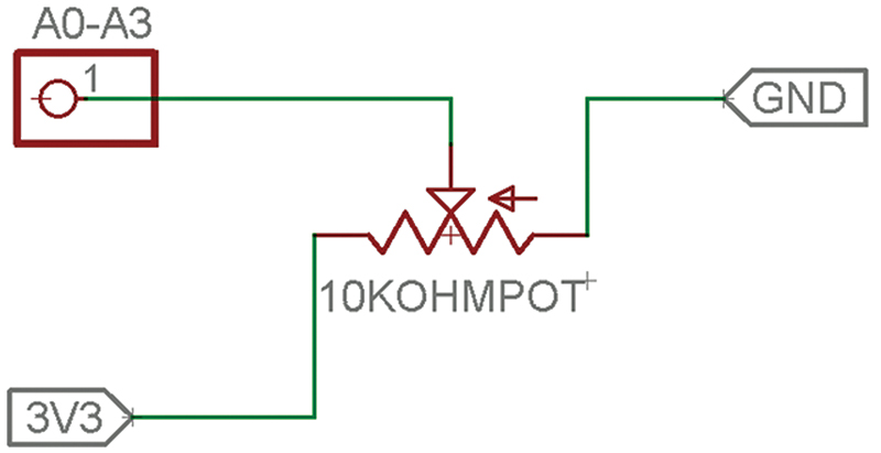
FIGURE 4.
Pins A0 to A3 are designated as pins 14, 15, 16, and 17 in the API. We will use pin A0 for this example.
1. Set the pin to an input using the command I14.
2. Set the pin to an analog state using the command A14. This sets the pin and returns the current value as a 10-bit integer.
3. Play around with the potentiometer and send the A14 command again to get a feel for the different readings. You should see a range from 0 to 1023. This function is limited to the pins listed above.
- Set analog pin to input — I, two digits for pin (14 to 17)
- Set pin to analog mode, read state — A, two digits for pin (14 to 17)
Test 3 — SERVOS
Standard servos usually run at 50 Hz. Sending a pulse duration between 1 ms and 2 ms at 50 Hz will cause the servo to rotate fully from one direction to the other. ISaAC uses a pair of pins (9 and 10) that can provide servo control signals using the API.
A servo has a three-wire connection: white for control signal; red for +5V; and black for ground. Use the 5V power and GND from the ISaAC to power the servo. You will also need an op-amp chip to drive the servo (I used the MAX908CPA quad op-amp). The LM124 works just as well (same pinout). See the op-amp in Figure 5.
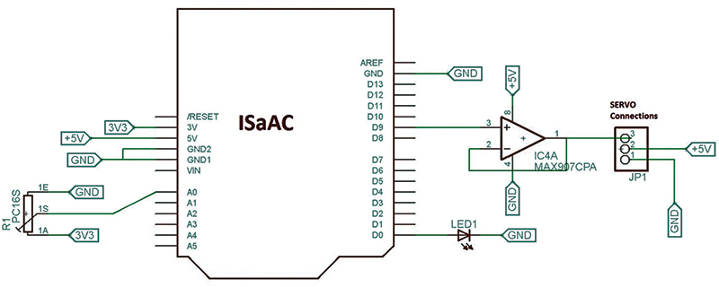
FIGURE 5.
No special level shifters are required in this case because the comparator is supplying power to the servo.
Note: Some pins on the ISaAC are not 5V tolerant.
1. To move the servo using 50 Hz frequencies with pin 9 connected to the servo white wire, use the following API command:
Z09000500000001500
This is pin 09 with a frequency of 00050 Hz, a delay of 0000 ms, and a pulse of 001500 ms.
2. To move the servo through its range of motion, change the Z parameter’s setting of the last four digits to 1200 and 1800.
- Set pin to output — O, either pin 09 or 10
- Send precision pulse command:
“Z” (two digits pin) (five digits<br />
frequency Hz) (four digits delay<br />
in ms) (6 digits pulse width in µs)
Installing Python Libraries
1. We set up the GPIO serial port for use earlier in this article. Now, we must install the Python serial library to use it. To do so, execute the following command as a superuser:
sudo apt-get install python-serial
2. ISaAC comes with an extended Python API Library (issaccomm2.py) for running ADC, normal commands, and servo position under Python. To use this within your Python programs, you must install it within your Python Code folder. The library provides Python 2.x support for the ISaAC board in RasPi applications. Automatic error handling and built-in help are included in the library.
3. To use this library, type:
import isaaccomv2
4. To invoke help at any time, type:
help (isaaccomv2)
5. Several API functions are provided in this version of the library, including:
- Simple API command execution
- ADC measurement (by pin)
- Analog out
- Pin assignment (digital or analog)
- PWM (by pin)
- EEPROM data storage and EEPROM data recall
- RTCC time set and read
- Alarm set and configure wake event (including power-up of RasPi)
- An API script build/recall/rewrite capability
To perform API calls in Python, use the form API_com (string). This function sends API commands directly to the ISaAC board. Here are some examples:
- Make ISaAC’s pin 1 a digital output: “API_com(“O01”)
- Set it high to turn on LED: API_com(“H01”)
- Set it low to turn off LED: “API_com(“L01”)
The command API_ADC(pinna) accepts a two-digit string for the pin number to measure (14, 15, 16, 17) and returns a two-component array (for example, echo, ADC_data = API_ADC(“14”). The first component is the echo response from the ISaAC board. The second component is a 10-bit integer value for the analog value of that pin.
For servo control, the API provides a higher level function servo position (servo value, servo pin). This function positions the servo to the servo_value, using pin 9 or 10 to provide servo control signaling. An example using pin 9 and the ADC data value is:
echo, ADC_data = API_ADC (“14”)<br />
servo position (9, ADC_data)
There’s also an API function that blinks a light on a pin for a designated time using the form blink (pin, time_val).
You already used the core API with Minicom to test and debug your hardware. Now, you can use this extended API within a Python file or directly with IDLE GUI. API usage is straightforward, supports project hardware tests, and makes code development easier by letting the user focus on the software debugging only.
Servo Control Using Python
Let’s run this project using Python to control servo position. The position of the servo will be set by reading a potentiometer.
1. Turn the pot CW, and the servo position will change in the CW direction.
2. Turn the pot CCW, and the servo will change accordingly. We will also throw in a blinking LED to indicate that the project is actively running. See the schematic in Figure 5 again for the entire setup. Go ahead and assemble this circuit.
3. Use the Extended API library for running ADC, normal commands, and servo position as discussed earlier.
A diagram of the prototype is also shown in Figure 6.
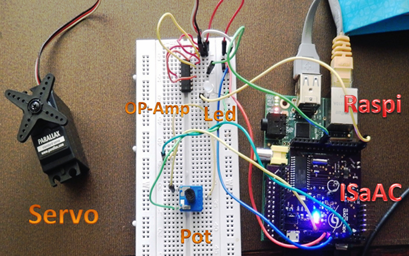
FIGURE 6. Servo control prototype.
ISaAC supplies power to the prototype electronics, servo, and RasPi with one micro USB. A solderless breadboard is used for auxiliary electronics and is connected to the ISaAC/RasPi via breakout connectors on ISaAC.
What’s Next?
We covered a lot of detail on ISaAC’s capability using the API. There’s more to come! This API ensures rapid development. Be sure to download the reference manual for examples on each API command, Flash programming the ISaAC, and more. If you’d like to purchase IsaAC, you can do so from the Nuts & Volts Webstore. NV
Back to text