"ACHTUNG! ALLES NONTEKNISCHEN LOOKENPEEPERS! DAS KOMPUTENDEVICE IST NICHT FÜR GEFINGERPOKEN UND MITTENGRABEN! IST EASY SCHNAPPEN SPRINGENWERKEN, BLOWENFUSEN UND POPPENCORKEN MIT SPITZENSPARKSEN! IST NICHT FÜR BETOUCHIN BEI DUMMKOPFEN. DER RUBBERNECKEN TURISTEN KEEPEN DAS COTTONPICKEN HÄNDEZEN IN DER POCKETS, RELAXEN UND WATSCHEN DER BLINKENLICHTEN!"
COMPUTER ON THE BLINK?
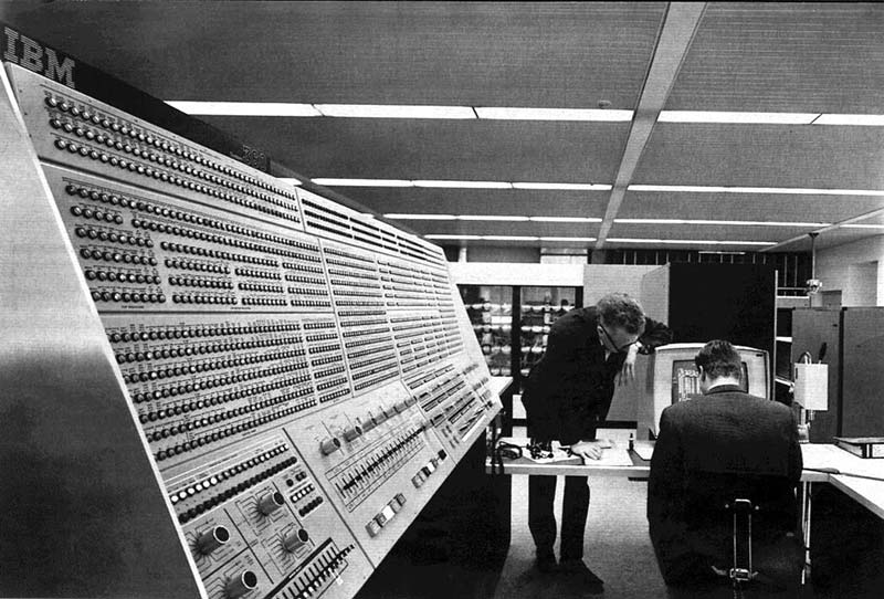
Ah, the inevitable blinking lights. In the early days of computing, the control panels of building-sized computers bristled with literally hundreds of switches and thousands of individual light bulbs (Figure 1).
FIGURE 1. IBM System/360 Model 91 at NASA in the late 1960s.
These rows and columns of indicators not only reflected what was happening inside these giant beasts, but they also provided data and diagnostic information to the operators.
From the public's perspective, "Das BlinkenLights" were synonymous with high technology. Control panels with indicator bulbs began to make appearances in science fiction movies such as "Destination Moon" in 1950 and then migrated to robots in the 1956 classic film "Forbidden Planet" where the seven foot tall "Robby the Robot" enthralled audiences world-wide. When computers finally shrank to a size (and price) that electronic hobbyists could handle, they brought their blinking lights with them.
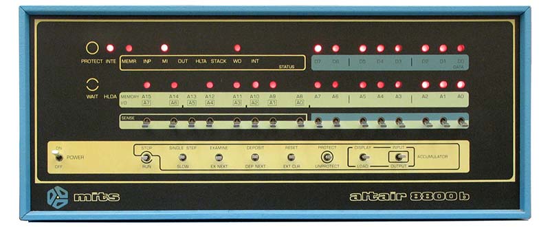
In January of 1975, anyone who bought a MITS Altair 8800 found it had rows of indicator LEDs for outputs and mini toggle switches for input (Figure 2).
FIGURE 2. MITS Altair 8800b.
The wide-spread adoption of CRTs coupled with exponential increases in computer bus speeds led to a vast reduction in the need for front panel lights. It wasn't long before many computers relegated the role of LEDs to simply showing power state or disk drive activity. However, the public's perception that "blinking lights = high tech" persisted.
Through the 1970s and ‘80s, it seemed many science fiction shows just couldn't get enough blinking lights. The Robot (a.k.a., "B9") of "Lost in Space" fame had both blinking lights in his brain-bubble and pulsating pushbuttons on his chest. The chrome-plated Cylons of “Battlestar Galactica” sported spiffy sequential sweeping red-lit "eyes." Even R2D2 had multi-colored twinkling dome lights to accompany his beeps and boops.
Though recent movie robots tend to look more human, when it comes time in the plot to declare their robotic heritage, they usually pry open a panel and show off a handful of LEDs as proof of true technological nature. So, if both the public at large and Hollywood persist in believing that all things high-tech should blink, then who are we to argue?
YABB (Yet Another Blinkin’ Board)
The search for a blinking light circuit was prompted when one of our regular Robot Group members, Marvin Niebuhr (a.k.a., "Professor Conrad"), expressed an interest in having a small circuit to blink lights in some of his bio-mechanical robotic art creations (see Resources). Though some members suggested that he could write some code for a microcontroller and just add some LEDs, he made it clear that he was more interested in building his sculptures than writing code and really preferred something simple ... something "turn-key."
As we are a rather helpful group of folks, many members started researching blinking light circuits from all over and many designs were discovered, suggested, and debated. Some circuits had LEDs lit by a decade counter chip driven by a 555 timer. Others used various combinations of dedicated logic chips to reach a similar end result. Newer designs used different microcontrollers to drive LEDs directly.
As we sought a "perfect" board, we kept coming up with features that were missing from the existing offerings or ideas on how the boards could be made more versatile and robust. These discussions brought about to a rather detailed definition of what would make a perfect board. One thing led to another and pretty soon James Delaney, Paul Atkinson, and I decided we should build a board that had all these features.
ON-BOARD VOLTAGE REGULATOR
Since a board can have either four AA batteries, a 9V cell, a 12V wall-wart, or 24 volts worth of gel cells for power, on-board regulation would allow it to be used in any power situation it might encounter in any of our existing robotic art pieces.
Being prepared for any type of power source would also make the device less likely to be damaged by improper power levels and would allow the board to be used by folks more interested in creating their robotic artwork than reading schematics and sourcing specific voltage power supplies.
A SMALL BUT POWERFUL, INEXPENSIVE MICROPROCESSOR
After considering various processors, it was decided that the Atmel ATtiny84 was the "just right" chip for this specific job. Smaller than the "overkill" Atmega8 in its massive 28-pin package yet larger than the somewhat cramped ATtiny45 with only eight pins (two of which are already allocated to power and ground!), the best of both worlds seemed to be the ATtiny84. It has enough pins to allow us to dedicate three to use for jumper settings while still leaving eight to use as outputs. In addition, if we're careful in how we allocate pins, we could even program the chip in-circuit! With 8K bytes of Flash memory, 512 bytes of on-chip programmable EEPROM, and 512 bytes of internal SRAM, the ATtiny84 packs a heck of a punch for a very low price.
LOW-SIDE BUFFERED SWITCHING
By using the robust ULN2803A Darlington driver chip to buffer the output of the microcontroller, we get multiple benefits. First, we up the number and type of devices we can drive. Since the ULN2803 can sink up to 500 mA per channel, it is capable of driving much heavier loads than the unbuffered output of the microprocessor itself. It's possible to power strings of LEDs and even incandescent lights. Also, the 2803 has built-in "snubber" diodes that protect against back EMF so the device can directly drive inductive loads such as relays, solenoids, and motors. Being a low side driver, it can be used to drive different voltage devices from different channels. For example, you could have a six volt light bulb on channel 1, a 12 volt motor on channel 2, a three volt sound module on channel 3, and a 24 volt solenoid on channel 4.
The trick is that since the chip is only switching the device to GND, the source voltage may be different for each channel. Lastly, it acts as a "sacrificial" part. If you short the output, you may lose the device itself, but the microcontroller is usually protected from damage.
RELIABLE “ON THE FLY” PROGRAM SELECTION
Rather than a hard-coded pattern determined by logic chips or a pushbutton switch that would have to be set after every power cycle, we wanted a simple and robust method to choose sequences. By using regular .100" jumpers, we can select a pattern and the unit will "awaken" with that pattern every time. Also, the pins can be connected to switches instead of jumpers to allow the sequence to be altered even after the board has been powered up.
NO ONE TRICK PONIES!
As our research turned up lots of "blinky" LED kits from various vendors, we had to make sure that ours was unique enough to justify building it rather than just buying something already available. As we went through the various scenarios that could benefit from a BlinkenBoard, we decided the key factor would be versatility. We wanted the board to be able to not only turn LEDs on and off, but to set their brightness levels via PWM. We wanted to be able to do more esoteric things such as drive and/or control the speed of standard DC motors, brushless motors, or even handle stepper motors.
We wanted to control both inductive and solid-state relays or drive solenoid valves for pneumatic devices. We wanted to be able to drive CCFT lights and incandescent bulbs. We wanted to be able to experiment with Persistence of Vision (POV) displays or drive speakers to make sounds. We envisioned controlling LED cubes and having the boards communicate via serial commands. And, of course, we wanted the ability to upgrade the system software so the board's role could evolve as future challenges were met.
VERY VERSATILE VERSION
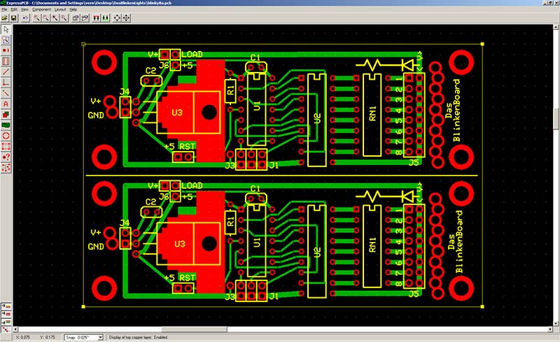
So, now that we had the specs, James picked up a previous project of his dubbed the "Generic LED Sequencer" and wrote new, more versatile software to fit the new design. Paul drew up the schematics and laid out a PCB in ExpressPCB (Figure 3).
FIGURE 3. Das BlinkenBoard “two up” layout in ExpressPCB.
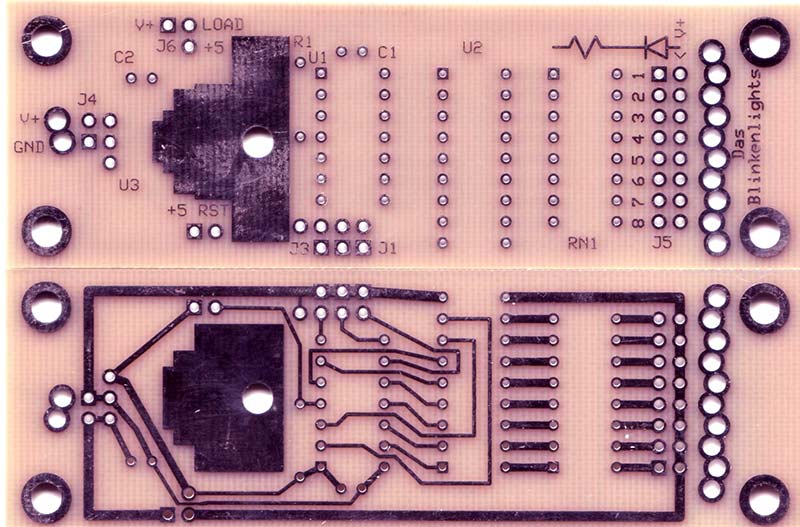
I ordered the boards (Figure 4) and then each of us took a turn at soldering up one of the prototypes to make sure everything worked.
FIGURE 4. Das BlinkenBoards from ExpressPCB's “Miniboard” service.
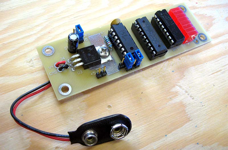
Paul built a board with the LEDs directly on the board and with power provided by a 9V battery snap. I built a board with the resistors omitted and had it drive a bunch of differing loads. James built one with a .100" 2x8 header and IDC connector pigtail with LEDs on the end. Every single one worked first shot out of the chute!
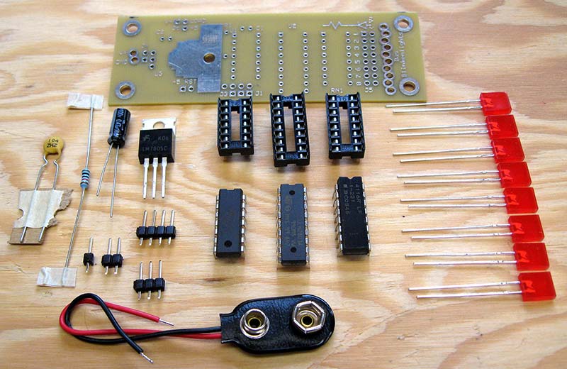
You should be able to build one of these boards yourself with the details in this article and all the software available at the downloads,. However, if you'd rather not go dig for parts and you'd like to take advantage of the bulk buying power the folks at the Nuts & Volts store have, we encourage you to stop by the store and order a kit (Figure 5).
FIGURE 5. Das BlinkenBoard kit of parts.
LET'S HAVE A LOOK AT THE SCHEMATIC
Before we warm up the soldering iron, it’s always a good idea to have a look at the schematic to see just what it is we're building. Though the schematic is laid out according to the specifications cited, a quick overview of its configuration and design features will help you to understand your options when it comes to assembly. Refer to the schematic in Figure 6 and follow along.
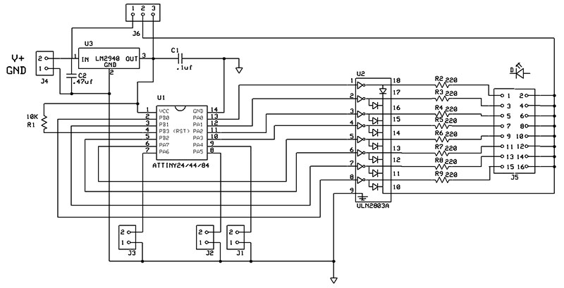
FIGURE 6. Das BlinkenBoard schematic.
Power comes into the board via J4 and may be provided by a 9V battery snap, tinned leads, or even a 12V PC hard drive power connector. Once on board, V+ is routed to the 7805 voltage regulator (U3) and C2 is used to filter any incoming noise from the power source. Power from the voltage regulator is used to feed 5V to the ATtiny84 (U1). J1, J2, and J3 are .100" header pins and are used to set the mode of operation on power-up and during operation of the board.
PA0-PA3 drive channels 1-4 of the ULN2803A Darlington array and PA7, PB2, PB3, and PB1 drive channels 5 through 8, respectively. NOTE: The seemingly random choice of pins that drives the 2803 was actually very much by design. The above order leaves RST, SCK, MISO, and MOSI unencumbered so that the chip can be programmed while in the circuit board.
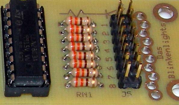
The 2803 then drives eight 220 ohm resistors used to limit the amount of current flowing through J5. J5 is designed to allow you to place eight discrete LEDs in a row on the board for the most compact setup. J6 is used to determine if the LEDs receive voltage from the 7805 regulator or directly from the V+ line. This allows you to choose if you want the regulator burdened with the current draw of the LEDs or if you would prefer the LEDs get their power directly from the voltage source.
AND EXACTLY HOW DOES THIS ALL LAY OUT?
When laying out the PCB, many things were taken into account in order to make sure the board was as versatile and robust as possible. For example, the J5 connector can be used to hold eight LEDs directly on the board itself (Figure 7) or it can be used with a .100" 2x8 header.
FIGURE 7. Rectangular LEDs fitted into .100” spaced holes.
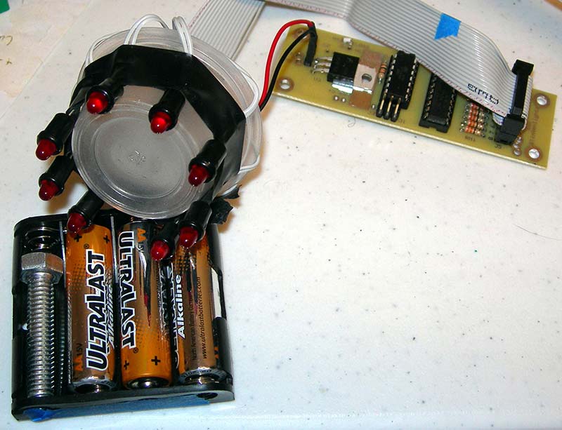
This way, an IDC style connector and some ribbon cable can be used to extend the load (be they LEDs or other devices) away from the board (Figure 8).
FIGURE 8. LEDs attached to the end of ribbon cable.
Note that the schematic shows eight discrete 220 ohm resistors and some of our prototype boards were indeed built in this manner (Figure 9).
FIGURE 9. Individual resistors mounted directly on Das BlinkenBoard.
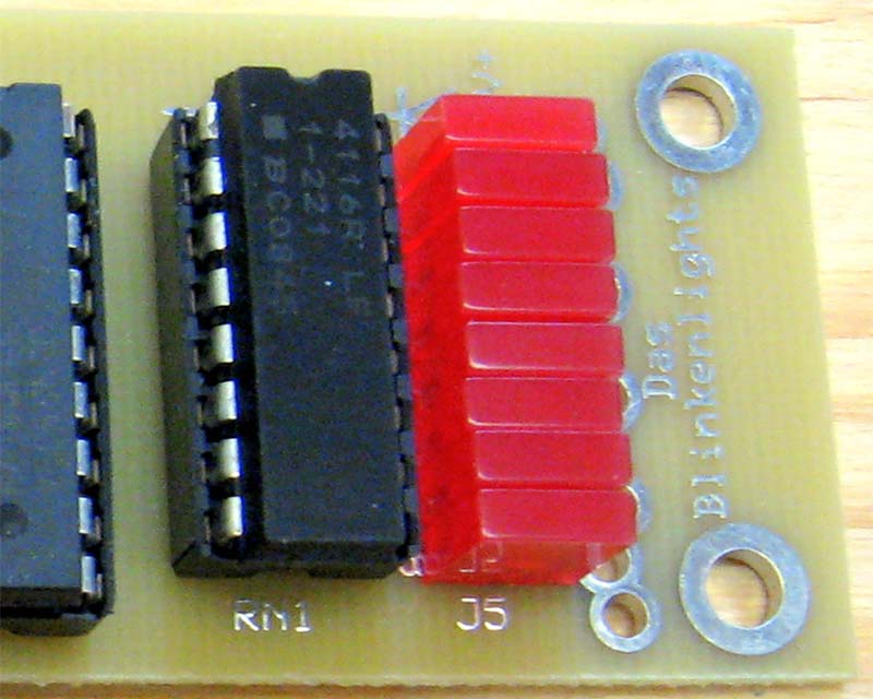
However, others were completed using a DIP socket with a resistor network (Figure 10).
FIGURE 10. Completed board with resistor network in DIP socket.
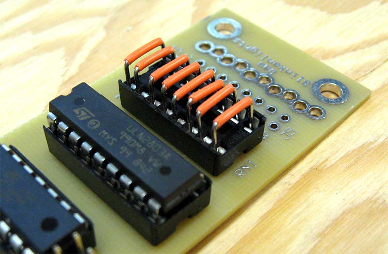
Using a socket allows you to change resistance values to accommodate different V+ voltages and/or different types/numbers of LEDs simply by replacing the DIP resistor network. In addition, the resistor network could be replaced by straight-wire jumpers (Figure 11) if the load being driven by the ULN2803A does not require current limiting.
FIGURE 11. Resistor network removed and shunts added into socket.
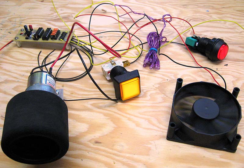
For example, in Figure 12 you can see the prototype board I built with channel 1 connected to an incandescent light bulb, channel 2 connected to a string of 10 high-brightness LEDs, channel 3 connected to another incandescent indicator light, channel 4 is connected to a brushless DC fan motor, and channel 5 is connected to a 12V DC gear motor and wheel.
FIGURE 12. A collection of non-LED loads Das BlinkenBoard can run.
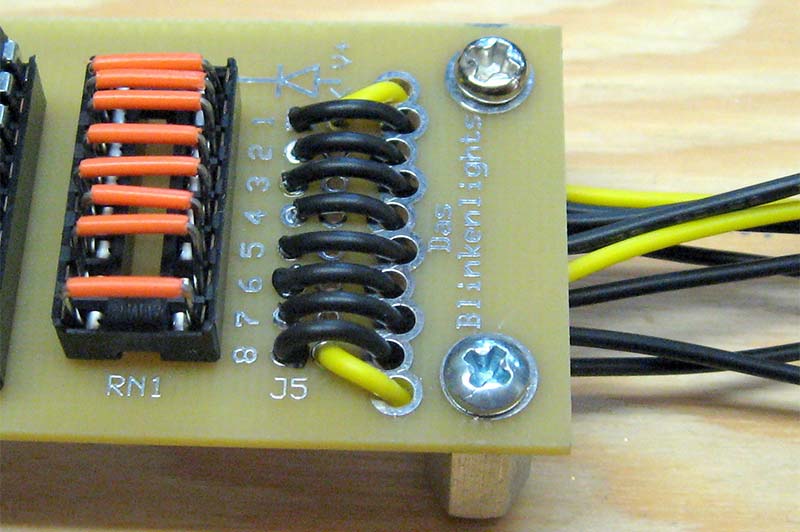
Another feature to make the board durable is the inclusion of stress relief holes along the edges where wires may be attached, such as J5 (Figure 13).
FIGURE 13. Das BlinkenBoard with wires threaded through stress-relief holes.
This way, if the loads connected to the board are mobile and/or they are shifted during installation or setup, there is a much lesser chance you'll be digging out a soldering iron in the minutes before a show!
THE SECRET IS IN THE SOFTWARE
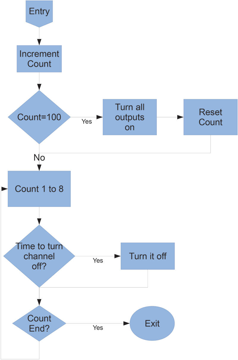
As mentioned earlier, the software was updated by James from his original generic LED sequencer. This new version defines an array of eight variables to hold a value for the pulse width modulation routine. This routine (Figure 14) is triggered by a timer interrupt to service the eight independent channels of PUM.
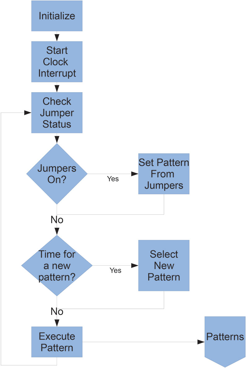
The main flow of the program (Figure 15) creates sequences by altering the values stored in this array of eight variables.
FIGURE 15. Main program flow.
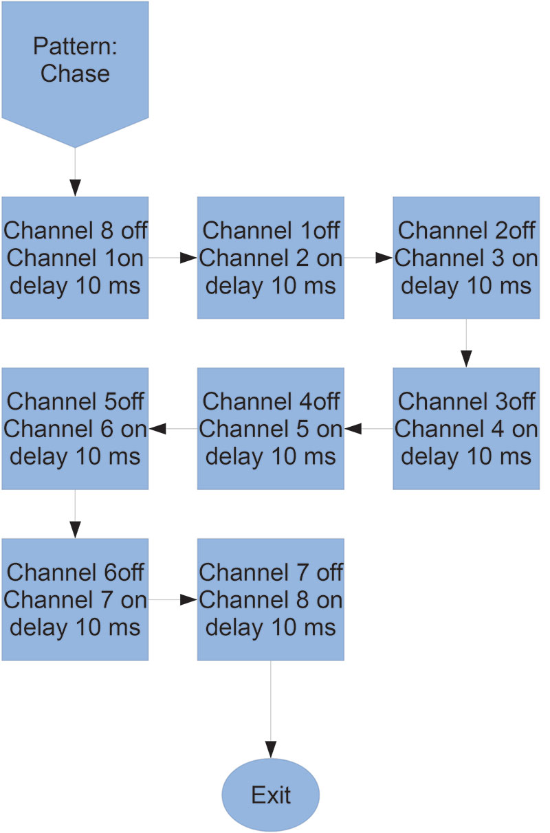
Figure 16 is an example of one of these sequence routines.
FIGURE 16. How a chase pattern is implemented.
The code is too long to include here, so please feel free to download and examine the code more closely. James has long wanted to convert me from my Basic programming to C so he went to the trouble of making an interesting and useful "Rosetta Stone" version of the software. This is a document presented in a two-column fashion that compares each of the C routines to a similar routine in pseudo Basic.
It's a very helpful document for understanding this code and also to help see the similarities between the languages. I would recommend it for those of you (like me!) who might be thinking of dipping a toe in the waters of C programming. James has released all the software for this project under the GNU public license. NV