Last time, we continued learning about Fritzing — a novice-friendly electronics hardware design package — useful for things like designing shields for an Arduino.
In this installment, we are going to finish our Fritzing workshops by tying up a few loose ends and then introducing some practical applications with a couple of very useful new kits that will let us easily implement Fritzing designs.
We will look at an Arduino proto shield and a breadboard battery that we will use to design an Arduino-based alarm clock on a breadboard (Figure 1) and then we will transfer that design to the prototyping area on an Arduino proto shield (Figure 2).
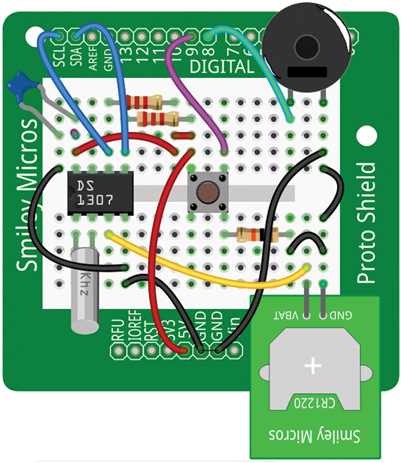
FIGURE 1. Fritzing image of proto shield alarm clock.
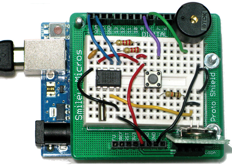
FIGURE 2. Arduino proto shield with alarm clock.
Finishing our Fritzing Workshops
Fritzing helps us see the connections
One of the main problems with photographs of wired-up breadboards is that the wiring can be incomprehensible and quite daunting to a novice. How on earth can you figure out where all those wires go and what is connected to what? One of the things that Fritzing is good at is allowing you to highlight a set of common connections on the board to help you see where things are located.
For example, if you hover the cursor over the GND header pin and press the left mouse button, you get all the connections appearing in yellow as shown in Figure 3.
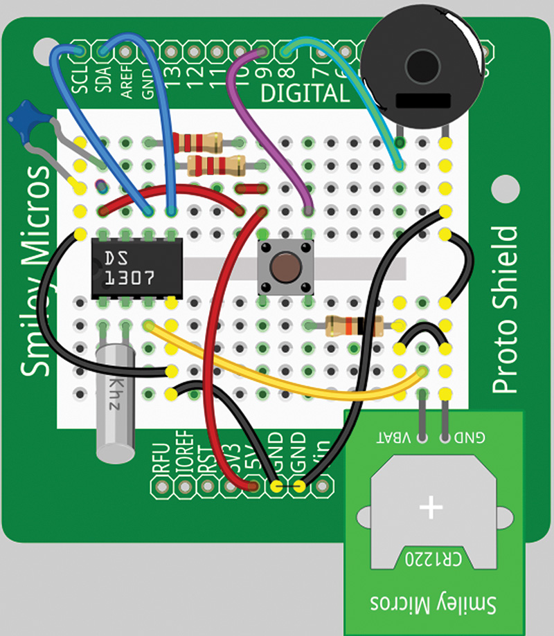
FIGURE 3. Highlighting GND.
Now, you can clearly see that both the upper left and upper right columns are connected to GND as is the capacitor plugged into the left upper column, the piezo speaker plugged into the right upper column, and the breadboard battery plugged into the lower right column.
We can likewise see all the +5 volt connections by highlighting the 5V header as in Figure 4.
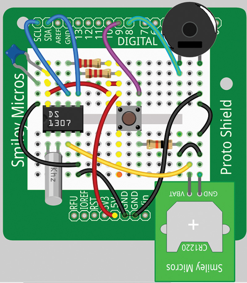
FIGURE 4. Highlighting +5V.
This shows how the two 10K ohm resistors, the left side of the pushbutton, and the leftmost upper pin of the DS1307 are all connected to +5V. I realize it is still a bit like trying to read a message spelled out in a bowl of spaghetti, but nonetheless it is better than a raw photograph (as you can see by comparing these images to the photo in Figure 2, which is actually quite clear compared to many you'll see).
Fritzing Mini Breadboard — Lighten Up!
When you open Fritzing, you'll see the full size breadboard in the breadboard view window. To change the full-sized board to a mini breadboard, go to the Part Inspector and select the size “mini” as shown in Figure 5.
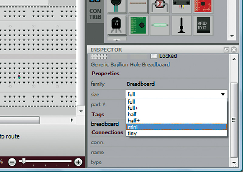
FIGURE 5. Select the mini breadboard.
The mini breadboard has 170 tie points and no power bus. In my opinion, it has a problem — it is too darn dark and hardly stands out against the background. So, I decided to lighten it up a bit and in so doing, show yet another example of how to modify a part by directly editing the .svg (scaled vector graphic) file. I opened the file Fritzing\parts\svg\core\breadboard\miniBreadboard.svg in Programmer's NotePad and changed the fill value from #D9D9D9 to #F9F9F9:
<g id="background"><br />
    <rect x="0" fill="#D9D9D9" width="129.839"<br />
    height="100.914"/><br />
</g>
to:
<g id="background"><br />
    <rect x="0" fill="#F9F9F9" width="129.839"<br />
    height="100.914"/><br />
</g>
This gives us the lighter image shown in Figure 6. This is — of course — a matter of personal preference, but I prefer the lighter version, so that's what I'll use.
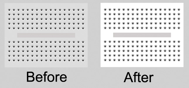
FIGURE 6. Piezo .svg drawing.
This bit of file editing is deceptively easy though, and you'll need to be very careful when trying to figure out what other sections of the file to do.
I suggest making a backup copy first; then for each little change you make, save the change and open the .svg file in a browser to see what you really did (drag and drop, then refresh to see the changes). You can learn a lot this way. You might also want to take a look at http://weblogs.asp.net/bleroy/archive/2011/08/09/building-a-simple-fritzing-component.aspx.
“Fritzing” an Arduino Proto Shield
We've already looked at Inkscape and decided to let you learn how to use that excellent program on your own. It isn't easy (none of the vector graphics programs are easy), but it is free.
If you want to make illustrations like the ones I'm using, it is an excellent tool. I used it to generate the Arduino proto shield image shown in Figure 7.
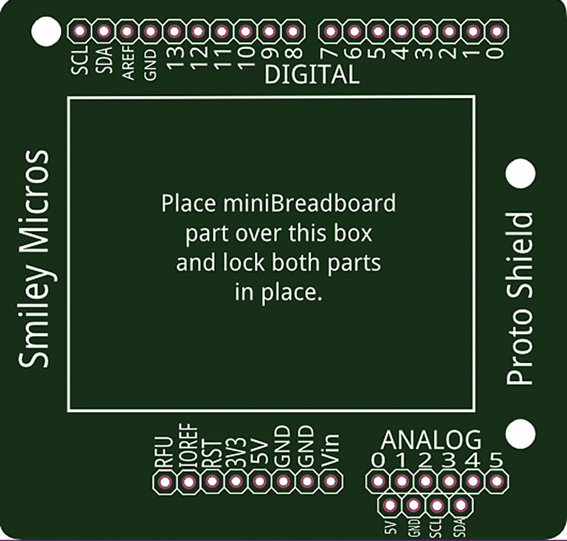
FIGURE 7. Arduino proto shield without breadboard.
You can learn more about generating your own custom PCB image at http://fritzing.org/learning/tutorials/designing-pcb/pcb-custom-shape.
You can get this Fritzing part at the download link at the end of this Workshop..
To use this in Fritzing, you add the shield to the breadboard view, then right-click the board, and select 'Raise and Lower' \ 'Send Backward as shown in Figure 8.
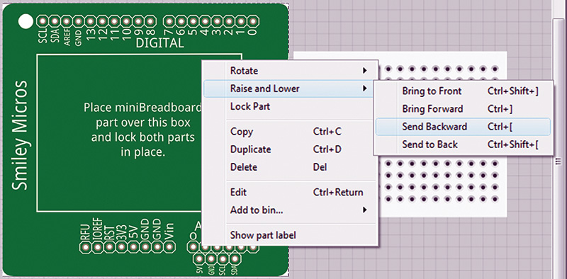
FIGURE 8. Send board to back.
Then, slide the board under the mini breadboard as shown in Figure 9.
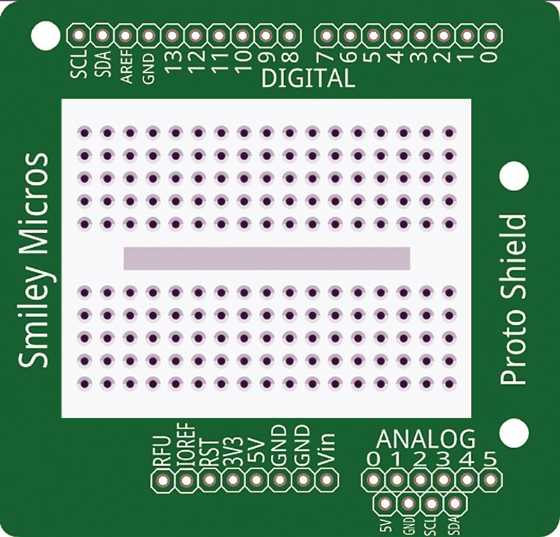
FIGURE 9. Proto shield with breadboard.
Introducing the Arduino Proto Shield
As I said at the beginning, the actual PCB is a bit different from what we show in Fritzing in that it has pads on the board that match the connections on the mini breadboard, and it has an extra set of connection points for the Arduino pins. This is shown in the photo in Figure 10.
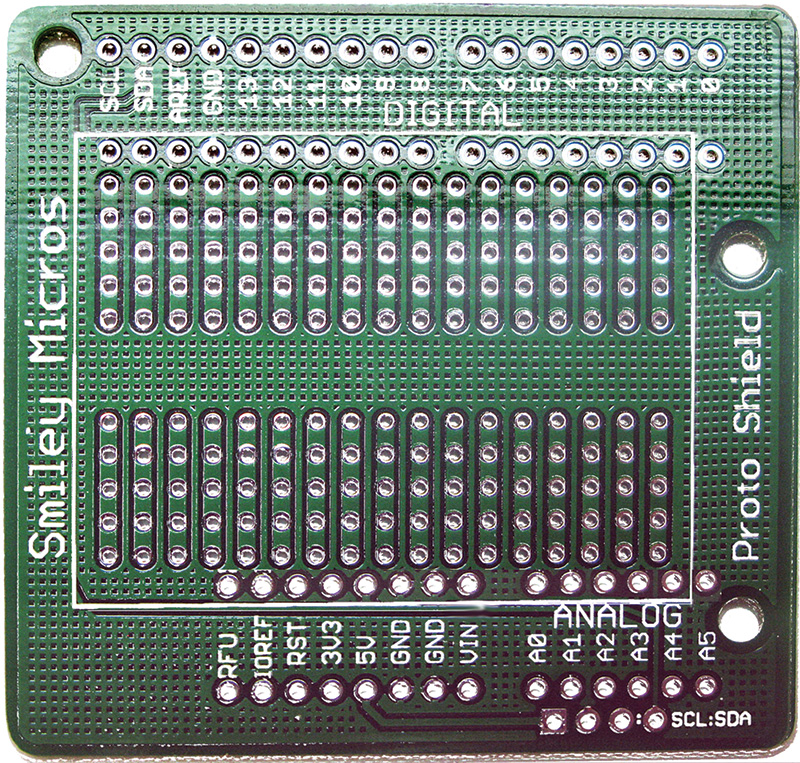
FIGURE 10. Proto shield PCB layout.
These pads will allow us to directly transfer a design that we got working on a mini breadboard to a proto shield, and solder the parts to the PCB. We'll do that very thing first thing in our next Workshop.
I didn't produce a Fritzing version of the final PCB showing all the holes under the breadboard area because it was just too darn difficult. The part editor kept messing up (but they do warn you that it is buggy) when I was trying to add all the pads to match the mini breadboard connections. I finally gave up and just used another CAD package that I'm competent with (Eagle) to design the PCB.
Breadboard Battery Backup
A real time clock IC like the DS1307 needs a three volt battery backup to keep track of time when the main power is removed. Since we can't be certain that the Arduino will always have power or even that the proto shield will always be plugged into the Arduino, we need a backup battery for our alarm clock. In Workshop #49, I issued a dire warning about not soldering wires to a coin cell battery for use with a breadboard — hey, they might blow up and you wouldn't want that. But, then again, the coin cell batteries are so darn convenient for battery backup, plus wouldn't it be great if there were some way you could use one with a breadboard? Yup, I'm leading to something here. You can get a breadboard backup battery like the one shown in Figure 11 from the Nuts & Volts webstore.
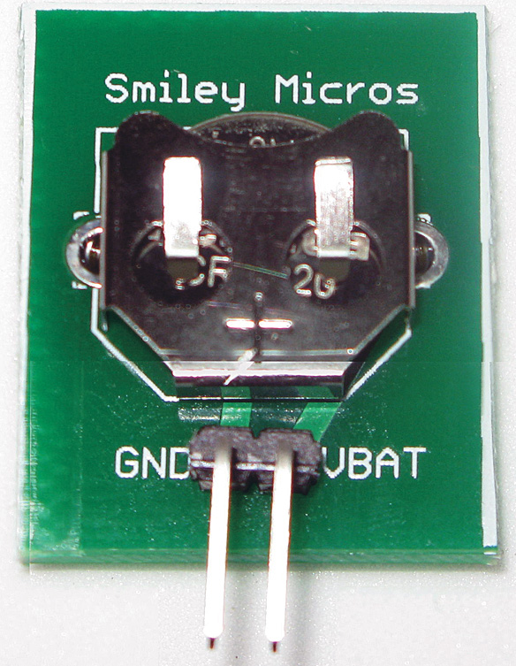
FIGURE 11. Breadboard battery with parts soldered on.
Figure 12 shows the part we'll use in Fritzing illustrations like in Figure 1.
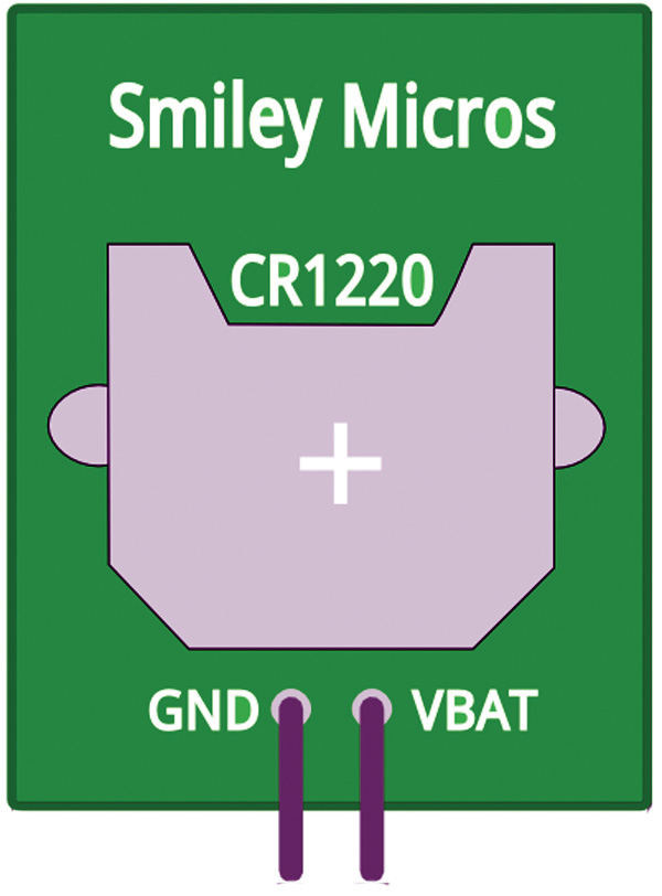
FIGURE 12. Fritzing part for the breadboard battery.
The kit shown in Figure 13 requires soldering — but not to the battery — and the battery is included. [IMPORTANT CAVEAT: These boards — to keep the costs low — are cut from panels using shears, so the edges may not be as smooth as you are used to. They will work just fine, but don't expect perfection in the finish.]
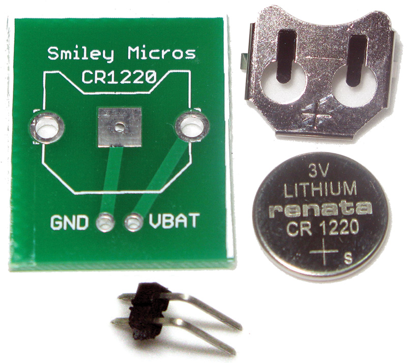
FIGURE 13. Breadboard battery kit.
We'll use this device to backup our DS1307 RTC on the following alarm clock project shown in Figure 14.
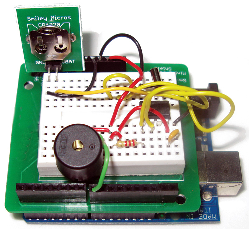
FIGURE 14. Breadboard battery in use.
An Arduino Alarm Clock
Let's say we take all we've learned recently about Fritzing and real time clocks, and build an Arduino alarm clock like the one back in Figure 2. This is far cooler than an ordinary alarm clock because it can talk to a PC over the Arduino USB port. This allows us to set the time with great accuracy from Internet sources, and it lets us set up alarms using a PC terminal interface (instead of a few buttons like you'd see on a regular alarm clock).
First, we will build the circuit on the mini breadboard, which is a great way to test that a prototype works. Once we get it working, we will transfer all the parts and wires to PCB pads that exactly duplicate the mini breadboard connections — this will let us take the tested design on the breadboard — which isn't all that robust — and move it to a PCB which is very robust. By robust, I mean how the circuit will handle being jostled around or dropped.
The breadboard will allow parts to come loose, but the PCB will have the parts firmly soldered down and be much more resistant to being thrown about. We will continue this into our next Workshop. (If you want to follow along, you can get all the components shown in Figure 15 and listed in Table 1 in the Arduino Proto Shield Alarm Clock Kit from the Nuts & Volts webstore.)
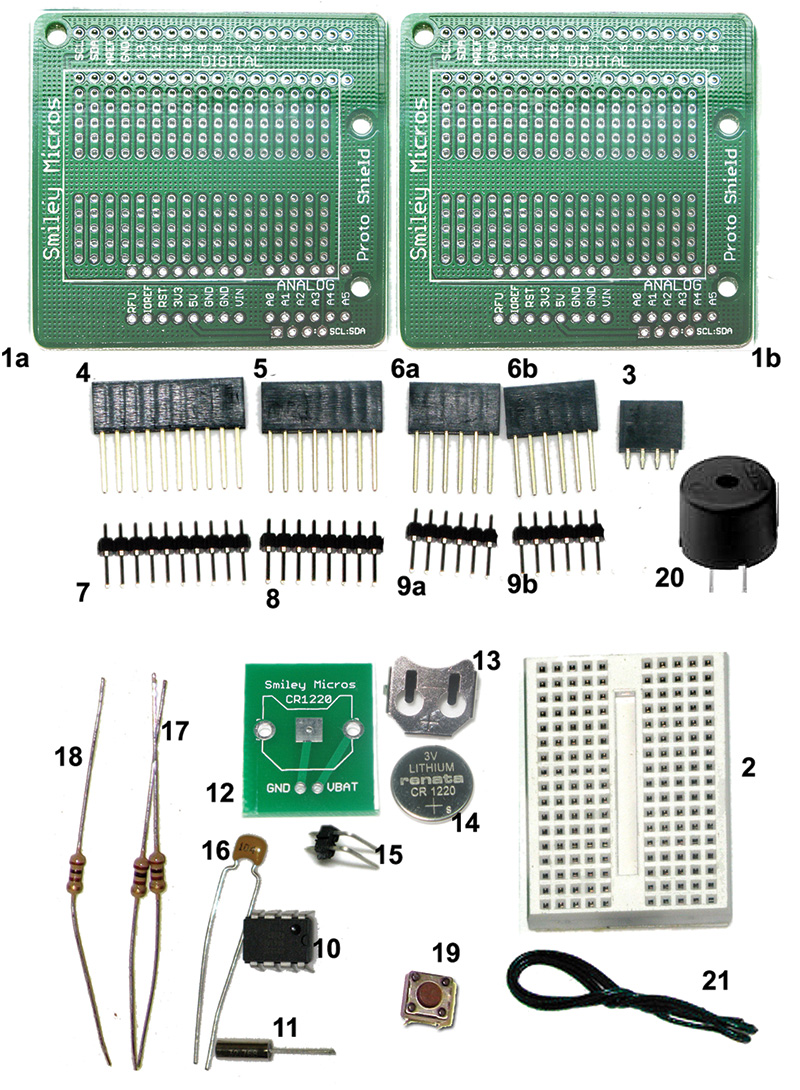
FIGURE 15. Arduino proto shield alarm clock project.
| Item |
Description |
| 1a, 1b |
Two proto shield PCBs |
| 2 |
One mini breadboard |
| 3 |
Four-pin female header |
| 4 |
10-pin shield header |
| 5 |
Eight-pin shield header |
| 6a, 6b |
Six-pin shield header |
| 7 |
10-pin male header |
| 8 |
Eight-pin male header |
| 9a, 9b |
Six-pin male header |
| 10 |
One DS1307 RTC IC |
| 11 |
One 32.768 kHz watch crystal |
| 12 |
One breadboard battery PCB |
| 13 |
One battery holder 12 mm coin |
| 14 |
One battery CR1220 |
| 15 |
One two-pin 90 degree male header |
| 16 |
One capacitor 0.1 µF |
| 17 |
Two resistors 2.2K ohm |
| 18 |
One 10K ohm pull-up resistor |
| 19 |
One pushbutton |
| 20 |
One piezo buzzer |
| 21 |
Two feet of uncut jumper wire |
TABLE 1. Bill of Materials.
Build it on the Mini Breadboard
Over the past several Workshops, we've seen how to build a DS1307-based real time clock, so let's apply that here and add a feature we haven't seen yet: an audible alarm. We will use the Fritzing piezo buzzer part we created last time; let's test that first.
You'll need a proto shield with the headers soldered on and a mini breadboard taped to the top like the one shown in Figure 2. Plug this into an Arduino, and add a piezo element and wires as shown in Figure 16.
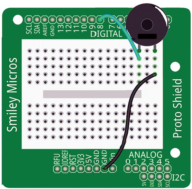
FIGURE 16. Proto shield with piezo buzzer.
This circuit is very simple as you can see in the schematic in Figure 17.
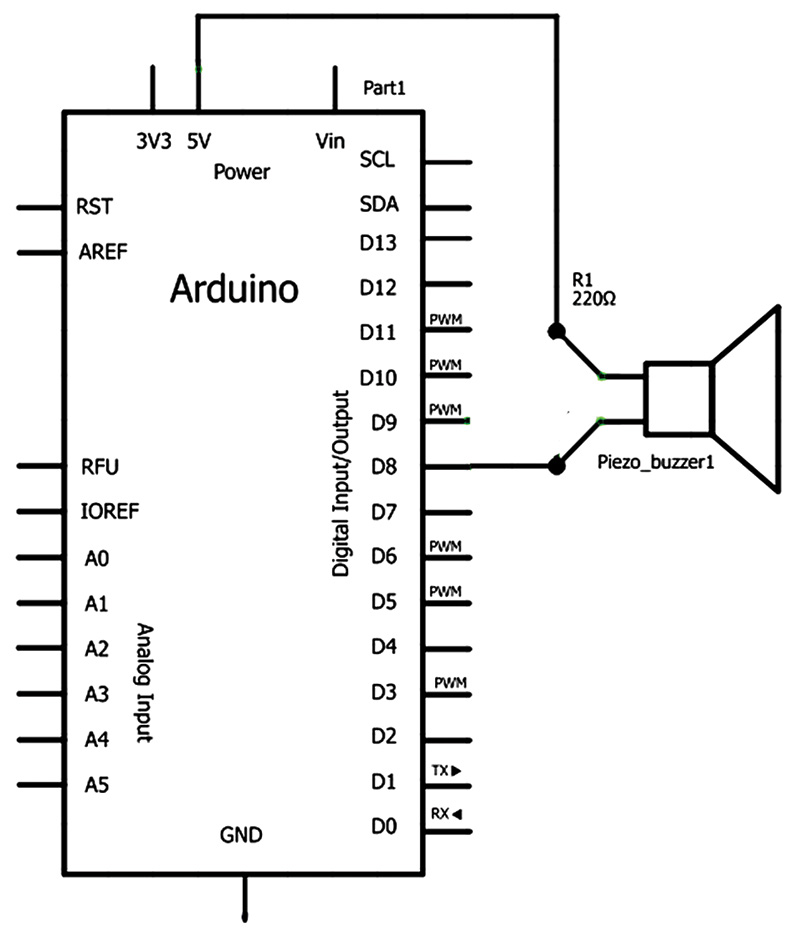
FIGURE 17. Piezo buzzer schematic.
Testing the Piezo Buzzer
We will use a program that comes with the Arduino IDE to do our preliminary tests. Open the toneMelody file in the Arduino IDE File\Examples\Digital\toneMelody as shown in Figure 18.
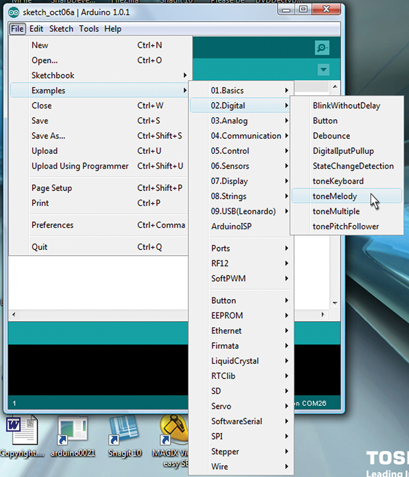
FIGURE 18. Select toneMelody.
This program should compile and upload to the Arduino without any modifications, and the piezo speaker should start playing the melody.
Making a Louder Alarm
So, that was kind of underwhelming. Yeah, it plays tunes but not very loud. We see from Figure 19 that the piezo buzzer volume is highly dependent on the frequency of the tone, so that while we can hear the music, most of the tones being played are fairly low volume. Note that the peaks are around 2,000 Hz and 6,000 Hz.
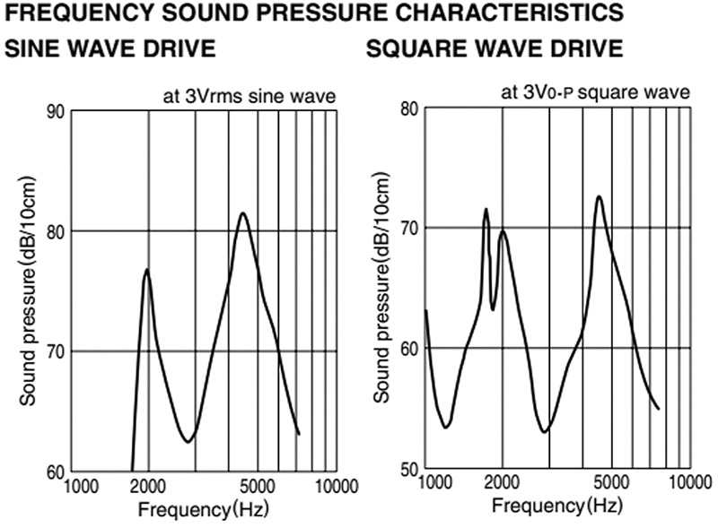
FIGURE 19. From the TDK PS1420P02CT datasheet.
This is an intentional design tradeoff for the piezo speaker since it wasn't really designed to play music, but to output annoying alarm tones that will grab our attention. Since that is exactly what we want, let's write a program to beep it around those datasheet frequencies and see if we can pinpoint a value that is loud enough to be worthy of the word alarm.
We first note that by using a real sine wave to drive the piezo versus a PWM square wave we get an additional 10 decibels in sound pressure. Is that worth adding the circuitry to convert the PWM to a sine wave?
Well, the square wave maxes out at a bit over 70 dB which is about as loud as normal table conversation (by normal I don’t mean at my family dinner table, but say that in a restaurant with babies and toddlers excluded).
A 10 dB increase is perceived as twice as loud. So, 80 dB would be about as loud as a food processor or garbage disposal. That would be ideal for an alarm, but let’s listen to the square wave induced tones first and see if they are loud enough for our purposes.
Test the Tone Volume as a Function of Frequency
The program allows you to play three tones each for 1/4 second, then wait a second before repeating them. You then manually change the frequencies to bracket the loudest tone. [As an aside, this is one of the greatest advantages of the Arduino. You can make minor changes in the code and reload rapidly, allowing you to make quick changes like this for testing purposes.]
I started off at 4,000, 4,500, and 5,000, and ran the program multiple times to bracket in on the tone I thought was loudest and most annoying (which, in my case, is 4,300 Hz). My hearing is a bit weird, so you may want to run your own tests to determine what is loudest and most annoying to you.
/* toneTest */
void setup() {<br />
 // do nothing<br />
}
void loop() {<br />
  for(int i = 0; i < 5; i++)<br />
  {<br />
    tone(8,4300);<br />
 // AND THE WINNER IS<br />
 // 4300!<br />
    delay(250);<br />
    tone(8,0);<br />
    delay(250);<br />
  }<br />
 <br />
  for(int i = 0; i < 5; i++)<br />
  {<br />
    tone(8,4312);<br />
    delay(250);<br />
    tone(8,0);<br />
    delay(250);<br />
  }<br />
 <br />
  for(int i = 0; i < 5; i++)<br />
  {<br />
    tone(8,4325);<br />
    delay(250);<br />
    tone(8,0);<br />
    delay(250);<br />
  }   <br />
 <br />
  delay(1000);<br />
}
The Real Time Clock Circuit
With the alarm program complete, we can add this to our earlier work with real time clocks from Workshop #48. You can construct the circuit shown in Figures 1 and 2 following the schematic shown in Figure 20.
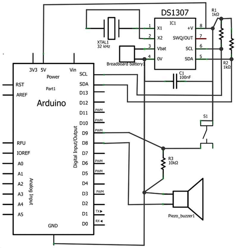
FIGURE 20. Proto shield alarm clock.
Test it with Arduino Software
Jean-Claude Wippler at JeeLabs wrote a most excellent library for using the DS1307 with an Arduino, so rather than reinvent a wheel, let's use his work. You can find it at https://github.com/jcw/rtclib. Unzip the library and load it into your Arduino directory at \libraries\RTClib. [This repeats the tests we saw in the Workshop #48, but rather than have to run that down we'll redo it.]
This library provides the DS1307 example shown in Figure 21.
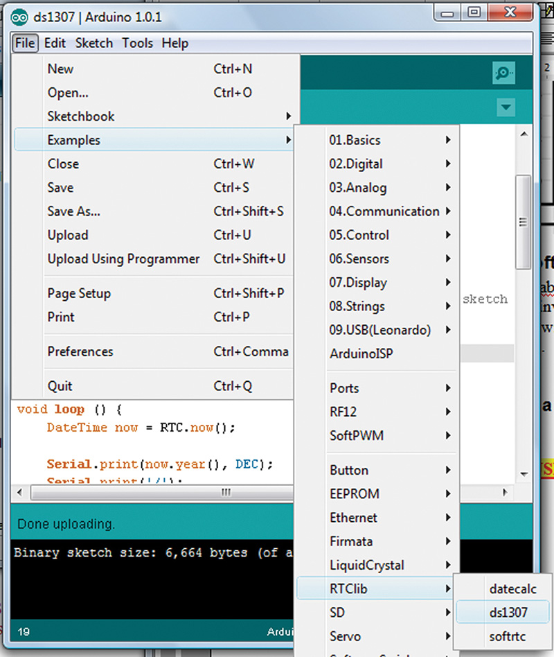
FIGURE 21. Select DS1307 in RTClib.
Open it and upload it to your Arduino with the proto shield. When you first run this, it will set the correct date and time based on what it reads rom your PC. Thereafter, if you keep the backup battery running at three volts (we'll get to that in a minute), it will continue to keep time.
Figure 22 shows the output of the program on the Arduino serial monitor.
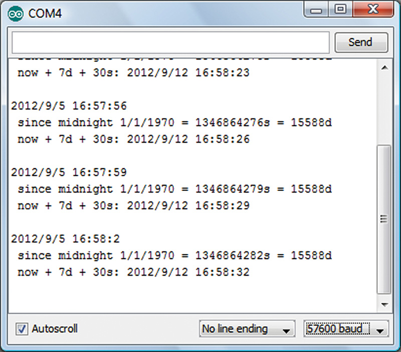
FIGURE 22. Serial monitor input.
In the first line, we see the year/month/day hour:minute:second. In the next line, we see the elapsed time since the Unix base time of midnight 1/1/1970 expressed as seconds and days. In the third line, we see the results of calculating a date which is seven days and 30 seconds into the future. Take a look at Jean-Claude's code and you'll see he has given you a really useful toolset for working with the DS1307 RTC.
So, now we have it all put together on a mini breadboard and tested it with some simple Arduino code.
Next time, we will continue with using the Arduino proto shield alarm clock kit by first transferring the parts from the mini-breadboard to the PCB to give us more robust hardware. Then, we'll write software for an alarm clock that is not only useful in itself, but provides a good basis for more advanced data logging projects.
This software will allow us to set alarms from the PC over the USB port, and use that button to shut the alarm off and generate various alarm tone sequences as needed. NV
Downloads
Fritzing part file for the Arduino Proto Shield.