This article introduces programmable relays as a means of building a smart doorbell. Programmable relays are microcontroller-based devices that can replace older hard-wired electromechanical control systems. A single programmable relay can replace an array of relays, timers, and counters.
Programmable relays use a visual language based on relay logic. Virtual devices are selected from a toolbar, configured from a drop down menu, and positioned on a ladder diagram between the power rails to achieve the required functionality (Figure 1).
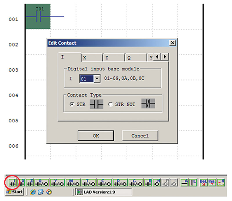
FIGURE 1. Ladder logic tool bar.
The TECO SG2 Client Software Version 3.37 illustrated in this article is downloadable for free from http://teco.us.com.
The visual ladder logic language was developed to ease the transition of people familiar with older electro-mechanical systems to newer microcontroller-based control systems.
The software allows for the simultaneous monitoring of multiple inputs, outputs, and virtual devices. Control functions can be complex, so the addition of comments into the ladder logic program can help to explain the workings of the system when in monitor mode (Figure 2).
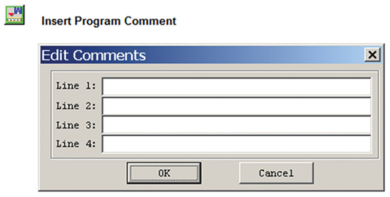
FIGURE 2. Program comments added to ladder logic provide helpful information.
Monitor mode allows an online computer to display the status changes of all inputs, outputs, and virtual devices as they occur.
The system designed in this article is a smart doorbell. It produces different ring patterns depending on when the door bell is pressed. The system utilizes a standard door bell and buzzer (Figure 3).
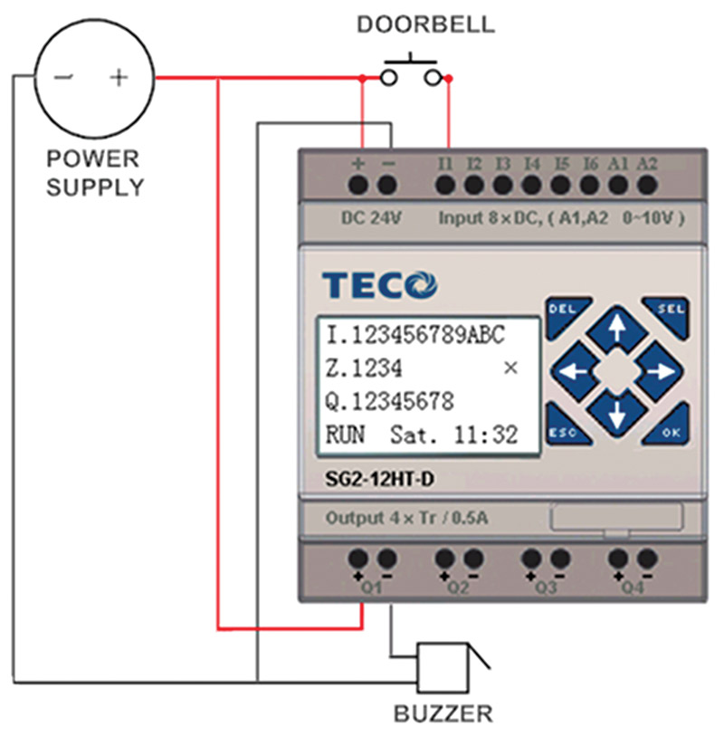
FIGURE 3. The smart doorbell utilizes a standard doorbell and buzzer.
The intelligence is added to the system by the programmable relay. The programmable relay used in this article is a TECO SG2-12HT-D. It is available from FACTORYMATION for $94. Additionally required is a SG2-Ulink cable for $33. Both are available at www.factorymation.com.
The status of the input and output terminals are indicated on the programmable relay’s visual display.
The display in Figure 4 shows that both input I01 and output Q01 are energized.
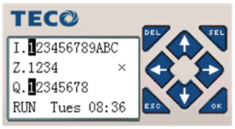
FIGURE 4. Status display shows I01 and Q01 energized.
The software was developed from the Listing of Circuit Requirements and refined by means of off-line simulation. Simulation mode allows a designer to test the software at various points to confirm operation before downloading the program into the programmable relay. The exact settings used in the smart doorbell program were not calculations. They were determined experimentally offline in simulation mode (Figure 5).
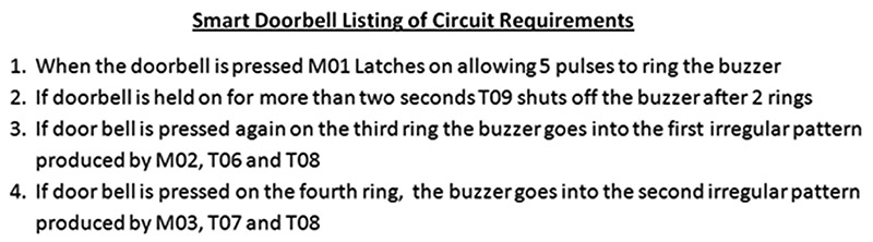
FIGURE 5. Smart doorbell listing of circuit requirements.
The complexity of a programmable relay based system is in the programming. Programming and future troubleshooting will be easier if the project is well organized. Programming spreadsheets help with this organization. Programming spreadsheets include: a brief description of the function of a circuit; a listing of inputs, outputs, and virtual devices; device settings; circuit requirements; and a rung by rung explanation of the program’s operation.
The top of the programming spreadsheet in Figure 6 shows that there are two external devices in the smart doorbell project: a doorbell switch wired to input I01 and the buzzer wired to output Q01.
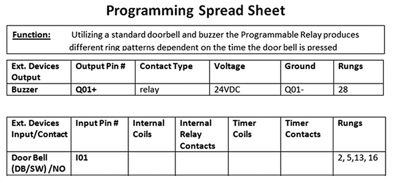
FIGURE 6. Top of programming spreadsheet.
Programming of the system is broken down into a set of parallel rungs, with each rung performing a particular function. In Figure 7, the momentary closure of the doorbell switch closes NO contacts I01 on rung 002, energizing internal relay coil M01 and timer coil T01, and closes NO contacts T01. T01 and M01 are latched ON until timer T01 times out in seven seconds.
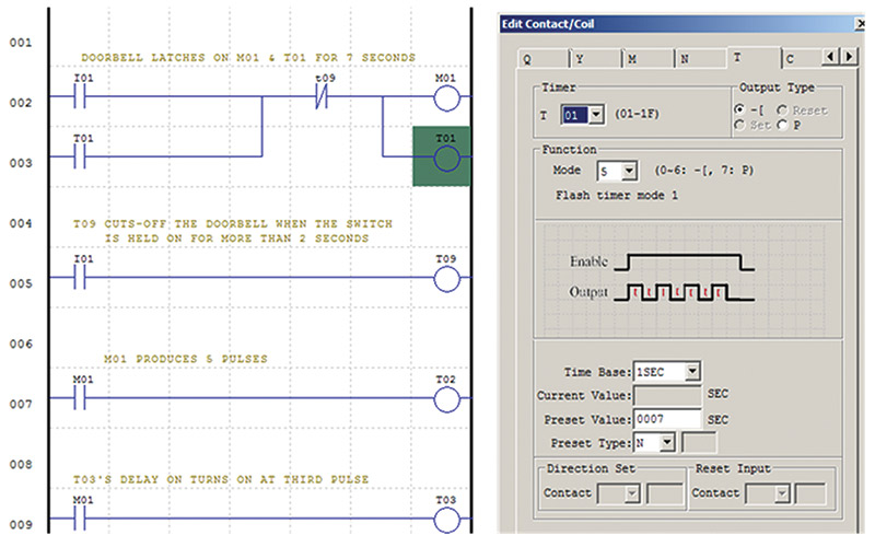
FIGURE 7. Rungs 001-003.
The proper configuration of T01 is shown in the drop down box on the right side of Figure 7.
If the doorbell is held for more than two seconds, timer T09 disconnects the doorbell. The doorbell will be disconnected after two rings and stay disconnected until the doorbell switch is released.
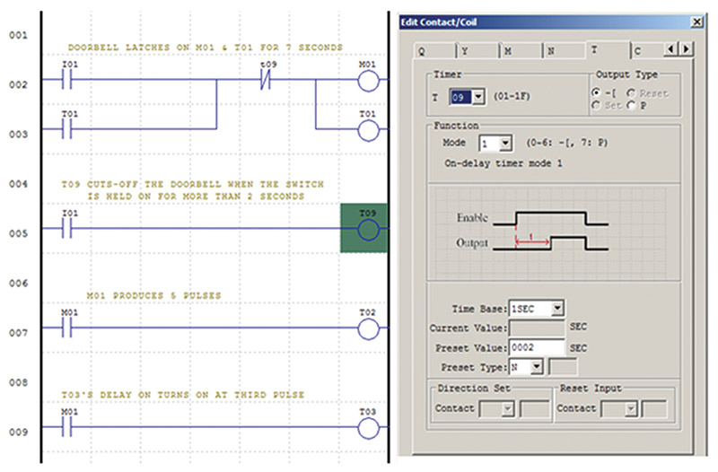
FIGURE 8. T09 disconnects the doorbell switch after two seconds.
The closing of NO contacts M01 on rung 005 enables T02 for seven seconds, giving T02 the time necessary to produce five pulses.
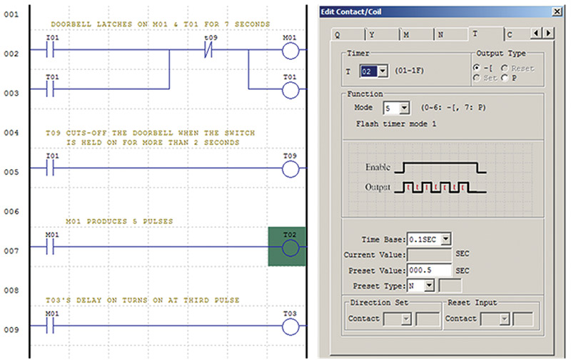
FIGURE 9. Rungs 004 and 005.
T02 on rung 028 pulses the buzzer five times when the door bell is pressed.
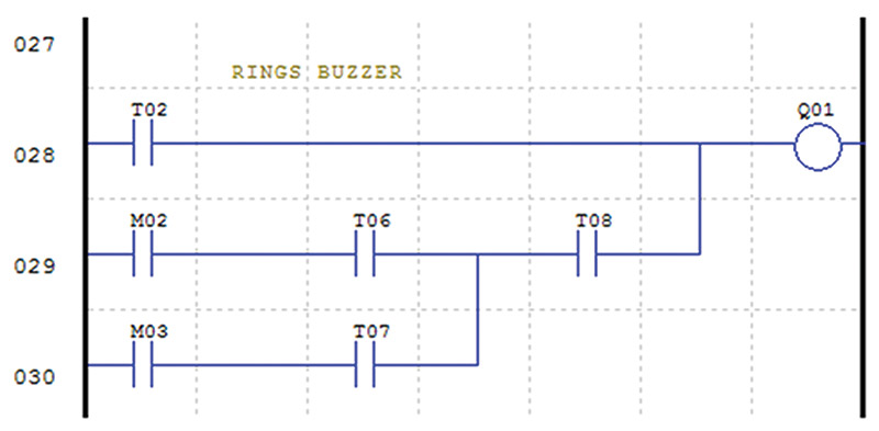
FIGURE 10. T02 rings the buzzer five times.
T03 on rung 009 is timed to turn on at the third pulse.
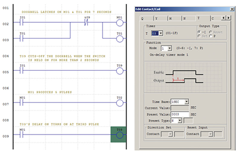
FIGURE 11. Rungs 008 and 009.
T04 on rung 011 is timed to turn on at the fourth pulse.
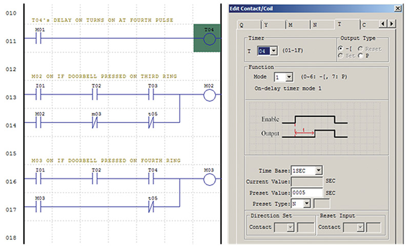
FIGURE 12. Rung 011.
M02 on rung 013 is on if the doorbell is pressed for a second time on the third ring.
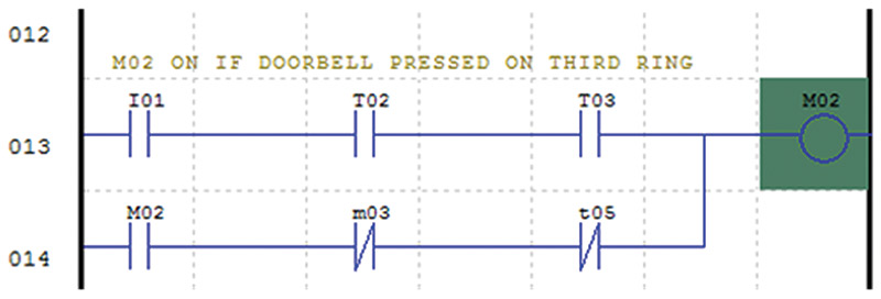
FIGURE 13. Rungs 013 and 014.
M03 on rung 016 is on if the doorbell is pressed for a second time on the fourth ring.
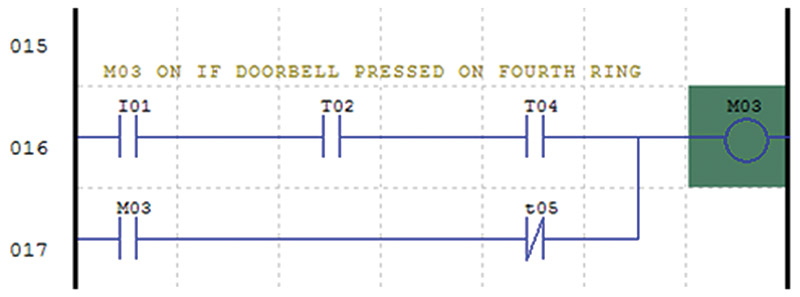
FIGURE 14. Rungs 016 and 017.
T05 on rung 019 is on if the doorbell is pressed during either the third or fourth ring. It causes M02 or M03 to stay latched on for 12 seconds, allowing adequate time for the specialty rings.
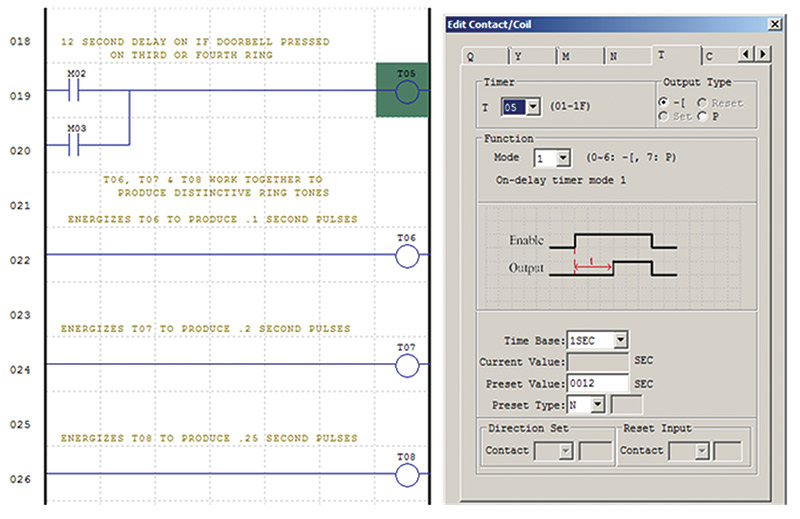
FIGURE 15. Rungs 019 and 020.
T06, T07, and T08 produce different period pulses. They are used together to produce complex identifiable ring patterns when the doorbell is pressed on the third or fourth ring.
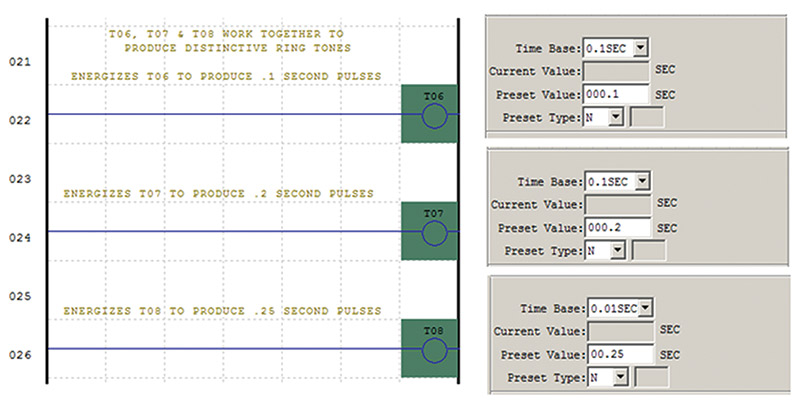
FIGURE 16. Rungs 022, 024, and 026.
The sound of the buzzer is modified on rungs 029 and 030 where the three pulses are mixed to produce the more distinctive pattern.
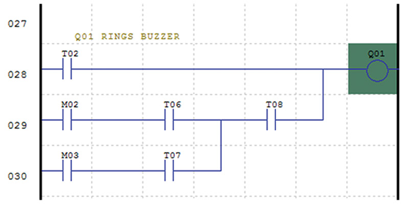
FIGURE 17. Rungs 028, 029, and 030.
The programming spreadsheet includes a record of all the device settings determined during the design and testing of the project.
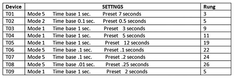
FIGURE 18. Smart doorbell settings matrix.
Programmable relay systems are electrically simple but operationally complex. The wiring is tested by the observation of indicators on the front display.
The programming spreadsheet allows the designer to organize the project, plus it provides valuable documentation for the future when technicians have to repair the system. NV