Most conventional firearms operate by the action of expanding gasses forcing a projectile out of a barrel at high speed. The propulsion for these systems is the detonation of gunpowder that causes an explosion behind a projectile positioned in a tube (barrel) that is closed at one end (the breech). Systems that operate on gunpowder are extremely loud and leave residue in the barrel and action making them prone to malfunction and requiring considerable cleaning efforts for continued use. With new research and innovation in high-tech electronic weapons systems, gunpowder may soon become a thing of the past.
See The Video
 |
Caution
The information contained in this article is dangerous and potentially life threatening. Use extreme caution when experimenting with high voltage and capacitor discharge circuits. If you are not experienced in the fabrication of such devices, then do not attempt to build this project. Always short out the capacitor bank when working with it or the circuit. Regular firearm handling precautions should be taken. Always wear eye protection. The author and the publisher accept no liability and will not be held responsible for any injury or damages caused by the construction, use, or misuse of this device.
|
|
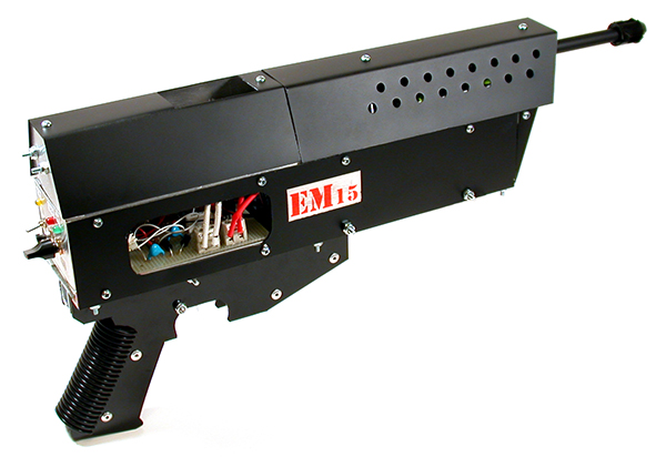
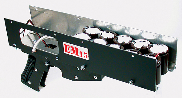
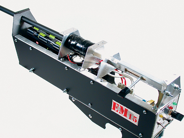
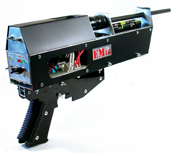
FIGURE 1. EM-15 electromagnetic coil gun.
|
|
 Are Coil Guns New? Are Coil Guns New?
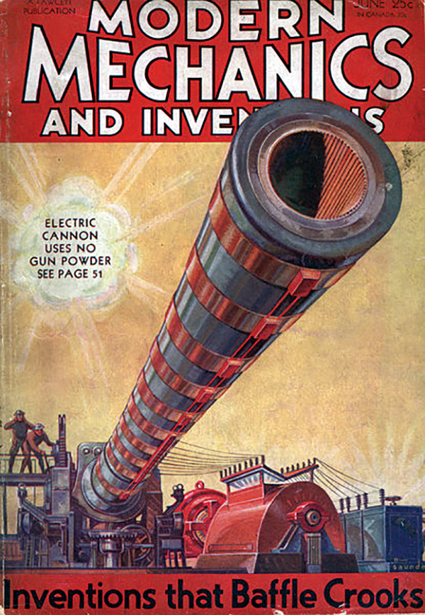
The concept of electromagnetic guns has actually been around for a while. The June 1932 Modern Mechanics magazine cover story featured an electric cannon built by an English designer named Dr. Kapitza. The story reported that the firing of shells was accomplished by shortcircuiting powerful dynamos for periods of 1/100th of a second.
 This approach sounds very similar to the modern compensated pulsed alternators (compulsators) being used to power the rail guns being developed at the University of Texas at Austin for the US Army electric gun program. For more information about the research going on at the University of Texas, visit their website at www.utexas.edu/research/cem/ This approach sounds very similar to the modern compensated pulsed alternators (compulsators) being used to power the rail guns being developed at the University of Texas at Austin for the US Army electric gun program. For more information about the research going on at the University of Texas, visit their website at www.utexas.edu/research/cem/
|
|
Coil Gun From the Past
 An interesting story was printed in the November 1936 issue of Popular Science about an electric machine gun. The gun was built by Virgil Rigsby of San Augustine, TX and was also featured earlier in a 1934 issue of Modern Mechanix. It was claimed that the gun could fire 150 rounds per minute using a series of electromagnets positioned along the barrel. An interesting story was printed in the November 1936 issue of Popular Science about an electric machine gun. The gun was built by Virgil Rigsby of San Augustine, TX and was also featured earlier in a 1934 issue of Modern Mechanix. It was claimed that the gun could fire 150 rounds per minute using a series of electromagnets positioned along the barrel.
|
Make way for the electromagnetic coil guns! These devices substitute electromagnetic (EM) propulsion for gunpowder with nearly equivalent results in speed and kinetic energy. What better way to get acquainted with this futuristic technology than to build your own electromagnetic gun!
The objective of this project is to design and construct a portable, self-contained electromagnetic coil gun. A coil gun is a type of rifle that uses an electromagnetic accelerator coil or a series of coils to accelerate a metallic projectile. The Strategic Defense Initiative of the 1980s — often referred to as “Star Wars” — was one of the first defense projects to realize the dream of futuristic electronic weapon systems development. A fully functional rail gun was developed for this program although it was never deployed in space.
Coil Gun Principles
Coil guns use a strong magnetic field to accelerate ferromagnetic projectiles. The projectiles used in coil and rail guns are often referred to as armatures. A large electric current is switched from a fast discharge storage device (usually a capacitor bank) into a coil of wire wrapped around a barrel to produce the strong magnetic field required for the rapid acceleration of the metallic projectile.
The projectile is situated at one end of the coil and is pulled to its center by magnetic induction. When the current is switched off, the projectile travels forward down the barrel, exits the gun and moves towards the intended target. The force applied to the armature is proportional to the change in inductance of the coil with respect to the change in position of the armature and the current flowing through the coil.
The force applied to the armature will always move it in a direction that increases the coil inductance. These systems are very quiet when projectiles are fired at velocities lower than the speed of sound, are clean, and require little maintenance. More advanced coil gun designs incorporate a number of accelerator coils switched in sequence as the projectile moves down the barrel.
The multiple coil design is intended to maximize projectile velocity. The major problem with electromagnetic weapons at the moment is the huge amount of energy lost when converting the electrical energy into kinetic energy.
Project Overview
This article will describe the general construction of the electromagnetic coil gun shown in Figure 1. The EM-15 coil gun is a hand-held, battery powered (12 VDC) rifle that is capable of launching a .30 caliber metallic projectile at adjustable velocities. This is a great project to explore a number of analog electronics concepts.
The electronic circuit consists of a voltage step-up transformer converter, a Cockcroft-Walton voltage multiplier cascade, a capacitor energy storage bank, a voltage comparator to set the charge voltage on the capacitor bank, an SCR switching section, and an accelerator coil. Other components of the gun are the barrel, breech loading mechanism, battery supply, control panel, display, projectile, pistol grip with trigger assembly, and an aluminum stock that contains all of the components.
The design, construction, and operation of the transformer used in this project is explained step-by-step since it is a key component that is often overlooked in articles and books concerning high voltage. When the gun is completed, it will be calibrated and fired. Be sure to watch the video of it in action at [url=http://www.thinkbotics.com/military.htm]http://www.thinkbotics.com/military.htm[/url]
Circuit Theory
 |
|
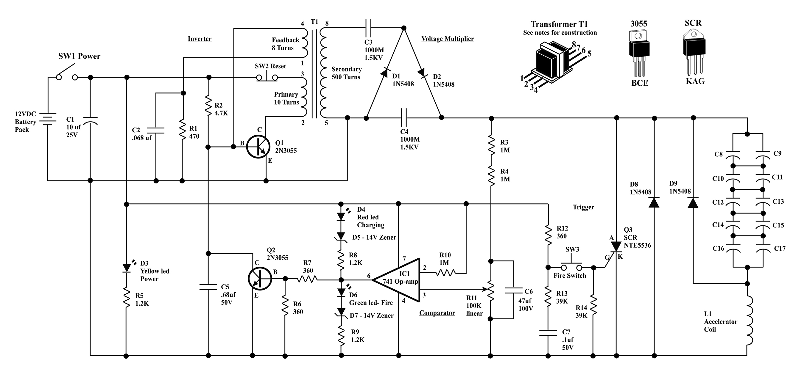
FIGURE 2. EM-15 coil gun schematic.
|
The EM-15 coil gun schematic diagram is shown in Figure 2. The inverter section of the circuit produces a high frequency, high voltage using an oscillator configuration consisting of transformer T1 being switched on and off by transistor Q1. When power is applied to the circuit by switch S1, resistor R2 initiates transistor Q1 to turn on and conduct a current of 12 volts DC through the primary winding (10 turns) of the transformer. The current passing through the primary winding induces a magnetic field in the iron core causing it to produce a current in the secondary (500 turns) and feedback (eight turns) windings. The feedback voltage holds transistor Q1 on as the current flows through resistor R1 and capacitor C2. Resistor R1 and capacitor C2 control the base current and operating frequency of the oscillator.
When the core of the transformer saturates, the induced base voltage goes to zero and turns the transistor off. The magnetic field in the ferrite core then collapses and produces 600 VAC in the secondary windings of the transformer. At this point, the transistor turns on again and the cycle repeats.
The high voltage AC output from the secondary winding of the transformer is doubled and rectified to 1,200 VDC by a Cockcroft-Walton voltage multiplier made up of diodes D1, D2, and capacitors C3, C4. The DC output voltage from the voltage multiplier charges the capacitor bank through the accelerator coil L1, to a voltage that is determined by IC1, a 741 operational amplifier configured as a comparator.
The Cockcroft-Walton voltage multiplier is an interesting device that was named after Douglas Cockcroft and Ernest Walton. In 1932, the scientists used this voltage multiplier cascade design to power a particle accelerator and perform the first artificial nuclear disintegration in history. The two eventually won the 1951 Nobel Prize in physics for “Transmutation of atomic nuclei by artificially accelerated atomic particles.” The voltage multiplier device was actually discovered earlier, in 1919, by a Swiss physicist named Heinrich Greinacher. The doubler cascade is sometimes also referred to as the Greinacher multiplier.
The capacitor storage bank is comprised of 10 1,500 µF, 200V capacitors configured to achieve 600 µF, 1,000V (C8–C17). These capacitors are available at most electronics supply companies. When the capacitor bank is charged to 800 VDC, the amount of energy that will be switched to the accelerator coil is 192 joules. With the capacitor storage bank charged to 1,000 VDC, the amount of energy is 300 joules. The capacitor bank should only be charged to 1,000 volts if you have installed an SCR that can handle it.
The 741 operational amplifier (IC1) is configured as a voltage comparator and is used to set the amount of voltage charge on the capacitor bank. The reference voltage for the comparator is taken directly from the 12 volt DC source through resistor R10. The voltage charge accumulating on the capacitor bank is dropped down to a value of approximately 1:20 through a voltage divider made up of resistors R3, R4, and 100K potentiometer R11, and is then connected to the comparator. The potentiometer is used to set the exact voltage level on the capacitor bank when calibrating and using the rifle. Note that the capacitor bank is charged through the accelerator coil.
When the desired voltage has been reached, the output of the comparator goes high and turns on transistor Q2 and the fire indicator light emitting diode D6. When Q2 is switched on, the base of Q1 is pulled to ground which stops oscillation of the transformer, turning the charging action off. If the gun is not fired immediately after fully charging, the voltage level on the capacitor bank will slowly start to decrease due to leakage and the comparator will turn the charging circuit back on to keep the capacitor bank voltage level topped off. You will notice the charge and fire LEDs gradually alternating on and off indicating that the comparator and charging circuit are maintaining the set voltage.
Once the capacitor bank has charged to the set level, a ferrous projectile is inserted into the breech loading device and positioned partially into the coil by the bolt. The bolt of the loading device has a small magnet in the end with enough force to hold the projectile in place if the gun is tilted forward, but not enough to interfere with the operation of it. When fire switch S3 is closed, voltage is applied to the gate of the SCR, switching it on and dumping the charge across the capacitor bank into the accelerator coil L1. The accelerator coil creates an electromagnetic pulse that launches the projectile down the barrel. Diode D9 is required to prevent the voltage from reversing.
Transformer Construction
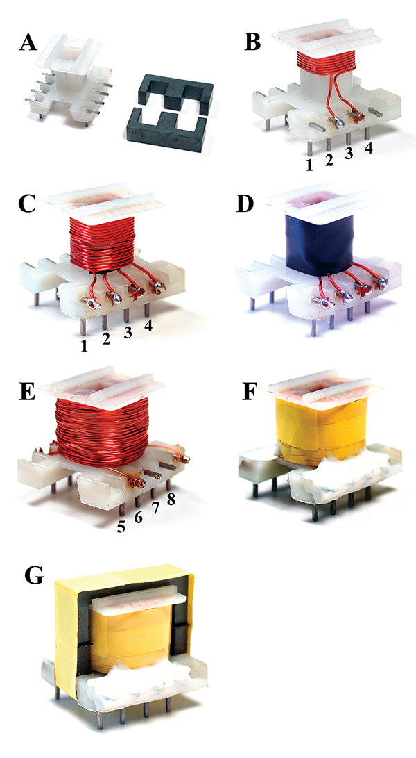
The heart of this project is a miniature high frequency transformer wound on a 20 mm x 17 mm x 15 mm bobbin with a ferrite core as shown in Figure 3. The primary winding consists of 10 turns of #26 AWG (American Wire Gauge) laminated magnet wire with an inductance of .008 µH, the feedback winding is eight turns of #26 AWG with an inductance of .006 µH, and the secondary winding is 500 turns of #34 AWG with an inductance of 20.6 µH. All inductance measurements were taken with the iron cores in place.
 |
 |
|
FIGURE 3. Transformer bobbin and ferrite core.
|
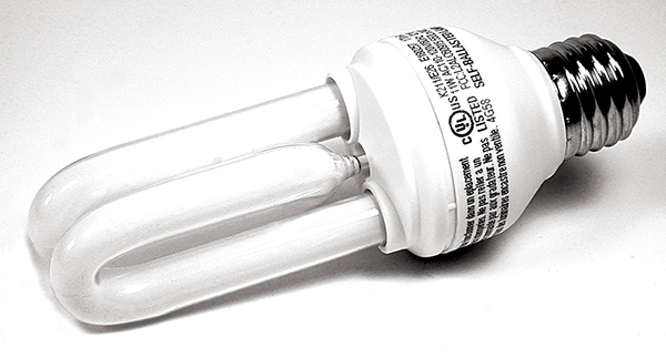
FIGURE 4. Transformer parts can be salvaged from an energy saver compact fluorescent bulb.
|
If you can’t locate a bobbin and core of similar dimensions at your local electronics store, then obtain a dead or unused energy saver compact fluorescent light bulb like the one shown in Figure 4. Crack open the lamp at the seam, being careful not to break the glass tube, and remove the circuit board. Locate the ferrite core transformer and unsolder it from the PCB (printed circuit board). Detach the core parts by unwrapping any tape that may be holding them together.
Use a knife or saw with a fine blade to cut the glue at the points where the core halves are in contact if the E-cores are glued together. There will probably be an air gap spacer on each side of the cores and in the middle so that the ferric material of each core does not contact. Don’t worry about destroying the gaps because we will be adding our own later. Remove all of the wire and tape from the bobbin.
 |
|
FIGURE 5. Transformer construction diagram.
|
It’s okay if your bobbin doesn’t have terminal posts since connector wires can be used instead. You should now have a bobbin and E-cores similar to the ones shown in Figure 5-A.
Start by numbering the bobbin posts from 1 to 8 in the positions shown in Figure 3. Solder one end of a piece of #26 laminated magnet wire to post number 2 and then wind the primary coil of 10 turns clockwise around the top half of the bobbin as shown in Figure 5-B. Solder the other end of the primary winding wire to post number 3. Using another piece of #26 magnet wire, solder one end of the wire to post number 1 and then wind the feedback coil of eight turns on the bobbin clockwise below the primary winding as shown in Figure 5-C.
Solder the other end of the feedback winding to post number 4. Next, cover the primary and feedback windings with a layer of electrical tape as depicted in Figure 5-D. On the other side of the bobbin, solder the end of a piece of #34 AWG magnet wire on post number 5 and then wind the secondary coil of 500 turns in even layers.
When hand winding the coil, you probably won’t be able to get the layers perfect but it won’t be a problem; just make them as neat as possible. Solder the other end of the secondary winding to post number 8 as shown in Figure 5-E. Wrap the secondary winding with a layer of transformer tape and then coat the solder connections with silicone rubber or a similar insulating material as shown in Figure 5-F. (I use a product called Plasti Dip that is available at most hardware stores.)
The final step in completing the transformer is to add the E-cores to the bobbin. To prevent the two halves of the cores from touching when they are in place, three air gap spacers need to be constructed. Cut three pieces of electrical tape to a size that is slightly bigger than the end of each of the three legs of one of the cores and then stick them on. Place the cores on the bobbin and tape that in place with transformer tape as shown in Figure 5-G. The transformer is now complete.
Building the Circuit and Control Panel
 |
|
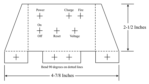
FIGURE 6. Control panel layout.
|
The circuit is constructed on a piece of 5-1/2 inch by 2-7/8 inch perfboard using the point-to-point wiring technique following the schematic. All of the parts necessary for the circuit are listed in the Parts List.
The control panel is constructed using 1/16-inch thick aluminum and can be mounted directly to the circuit board. A suggested metal cutting and drilling template is shown in Figure 6. Mount the potentiometer, indicator LEDs, and switches to the control panel and then fasten it to the circuit board. Use two position terminal blocks on the board where the capacitor bank, battery pack, fire switch, and accelerator coil are connected. The completed circuit board with control panel attached is shown in Figure 7.
 |
|
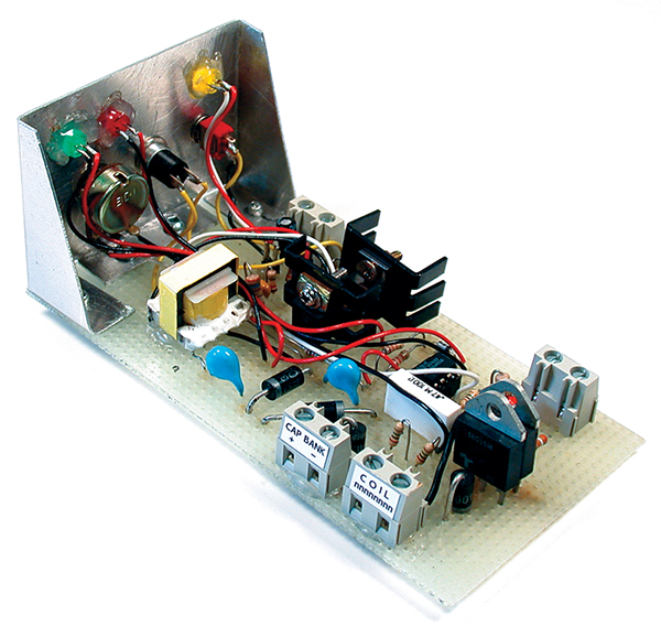
FIGURE 7. Completed circuit board and control panel.
|
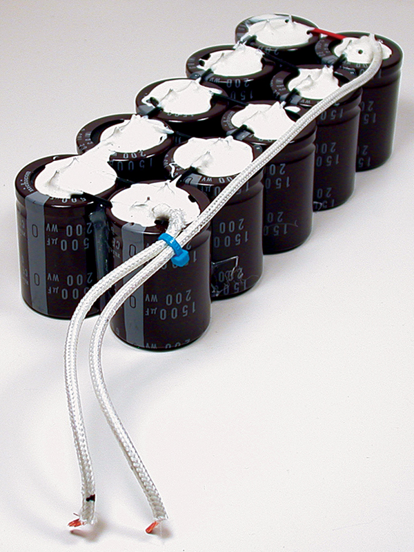
Capacitor Bank
Build the capacitor bank using 10 1,500 µF, 200 volt capacitors wired according to the diagram in Figure 8. This capacitor configuration gives a total capacitance of 600 µF at 1,000 VDC. Solder a 12 inch piece of high voltage wire to the positive side of the capacitor bank and a six inch piece of HV wire to the negative side of the capacitor bank as shown in Figure 9. The length of these wires may be different, depending on what type of stock you decide to build. Coat all of the capacitor leads and solder connections with RTV silicon rubber or Plasti Dip for safety. The completed capacitor bank is shown in Figure 9.
 |
 |
|
FIGURE 8. Capacitor energy storage bank wiring diagram.
|
FIGURE 9. Completed capacitor bank.
|
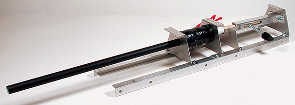
Accelerator Coil, Barrel, and Breech Loading Mechanism
The barrel consists of a 14 inch length of styrene tubing with an inner diameter of 7/16 inch. You can use any sort of light plastic or nylon tubing material that can be obtained at most hobby shops. Wind 300 turns of #20 AWG magnet wire, in six layers of 50 turns each. Start winding the coil one inch from the end of the tube. Cover each layer of 50 turns with electrical tape to secure in place and then wind the next layer on top. Use two plastic or cardboard discs glued to each end of the barrel on both sides of the coil to add support.
 |
|
FIGURE 10. Accelerator coil, barrel, and breech loading mechanism.
|
 |
|
FIGURE 11. Pistol grip cutting guide.
|
 |
|
FIGURE 12. Completed pistol grip with fire switch mounted.
|
Fabricate a breech loading device to move the projectile into a position where it is partially seated in the coil. You will need to experiment with the initial position of the projectile to achieve the highest velocities. The bolt of the loading mechanism that I put together contains a small magnet that holds the projectile in place when the gun is tilted, but does not have enough magnetic strength to interfere with the pulse created by the accelerator coil. The completed accelerator coil, barrel, and breech loading mechanism are shown in Figure 10.
Pistol Grip and Trigger Switch
The trigger switch used is a microswitch type but any momentary contact switch can be used. The pistol grip can be configured however you like, just as long as you can mount a fire switch. A general pistol grip construction template is shown in Figure 11 and can be fabricated out of plastic or aluminum.
Cut two identical pieces of plastic or aluminum and add support pieces of one inch square aluminum tube. Solder a length of two-strand wire to the common and normally open contacts on the microswitch. If you use a momentary contact switch, make sure that it is normally open.
Another alternative is to cut the pistol grip and trigger from one of the many inexpensive toys that are available on the market and rewire the switch. The completed grip with fire switch is shown in Figure 12.
Fabricating the Stock and Side Panels
 |
 |
|
FIGURE 13. Aluminum covers and side panels.
|
FIGURE 14. Capacitor bank, side panels, and trigger assembly.
|
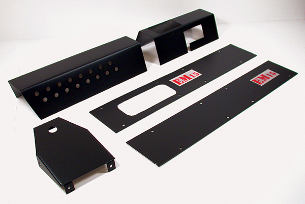
The stock for the EM-15 was fabricated with 1/2 inch aluminum angle and 1/16 inch thick flat stock but you can use whatever material you have access to. A metal bender was used to shape the pieces and all holes were made with a drill press. The side panels and covers are shown in Figure 13. The capacitor bank, side panels, and trigger assembly are shown in Figure 14. A closer view of the adjustable breech mounted to the rest of the gun is shown in Figure 15.
 |
|
FIGURE 15. The adjustable breech is ideal for experimentation with different types and initial positions of projectiles.
|
Assembling and Calibrating the Gun
I suggest setting up all of the electronic components on your workbench to calibrate the gun before assembling all of the parts into the stock. Connect the 12 volt battery pack, fire switch, accelerator coil, and capacitor bank to the circuit board. Be very careful not to touch the circuit board or any of the connections while testing the device. If you need to rewire or make an adjustment, then disconnect the battery pack and be sure to short out the capacitor bank.
 |
|
FIGURE 16. Side view of control panel and circuit board.
|
Set your multimeter to measure DC and then clip the leads to the capacitor bank terminals. Place a fresh set of batteries into the battery holder and turn the voltage potentiometer R11 all the way counter-clockwise and then turn on the main power switch. The ‘power’ and ‘charge’ LEDs should turn on. You will see the voltage rise to approximately 350 volts DC at which time the ‘fire’ LED turns on and the charging action will stop.
Mark 350V on the control panel at that position with a pencil or marker. Slowly turn the potentiometer clockwise until the voltage is 400 VDC and make another mark on the panel there. Continue this procedure in increments of 50 volts until you reach 800 VDC, marking each position of the potentiometer on the panel face with a pencil or marker as you go. Be sure not to charge the capacitor bank over 800 volts unless you have installed an SCR that can handle it. The control panel and circuit board can been seen in Figure 16.
Suitable Projectiles
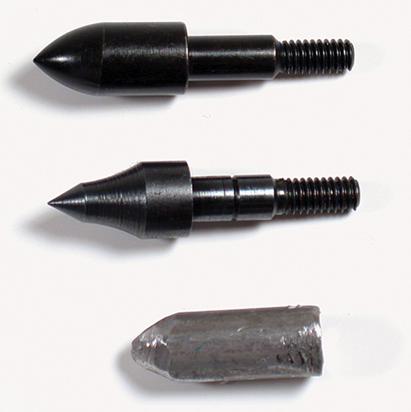 |
|
FIGURE 17. EM-15 coil gun projectiles.
|
A 1/2 inch projectile can be cut from a piece of .30 diameter cold rolled steel and then filed on one end for a more aerodynamic shape. I found that iron crossbow/archery tips (available at Wal-Mart) make ideal projectiles for this type of coil gun . Three of the different projectiles that I have used with success are shown in Figure 17.
If you decide to fabricate your own projectiles, then experiment with different sizes and weights until you find one that works well.
Firing and Velocity Measurements
Set up a proper backstop when you are ready to fire the gun and always wear eye protection when operating the device. The velocities listed in Table 1 were measured with a commercial chronograph. The projectile used for the measurements was an eight gram crossbow tip like the ones shown in Figure 17. The EM-15 coil gun stays well below the legal velocity limits in Canada and the US, but because of the projectile weight, it should still be considered dangerous. Regular firearm handling precautions should be taken.
| Voltage |
Projectile Weight |
Velocity (ft/sec) |
Velocity (meters/sec) |
| 400 |
8 grams |
57 |
17.37 |
| 500 |
8 grams |
64 |
19.51 |
| 600 |
8 grams |
70 |
21.34 |
| 700 |
8 grams |
81 |
24.69 |
| 800 |
8 grams |
91 |
27.74 |
| 900 |
8 grams |
101 |
30.78 |
| 1000 |
8 grams |
129 |
39.32 |
| TABLE 1. EM-15 velocity measurements. |
Conclusion
The EM-15 coil gun design can be used as a starting point for more advanced experimentation. Improvements can be made to the charging circuit, capacitor bank, accelerator coil, and barrel design to achieve higher velocities. Try designing a system with multiple coils, capacitor banks, and a switching device. A capacitor bank configured for higher capacitance and higher voltage can be used, but be sure to replace the SCR with one that can handle the increased voltage and amperage.
A design using a microcontroller to coordinate the switching, charging, voltage monitoring, and display would make a multiple coil design much easier to implement. The smooth bore barrel causes problems with accuracy because the projectile does not spin to stabilize it while in motion. Try to come up with some sort of rifled barrel or perhaps adding stabilizing fins to the projectile.
Remember that safety always comes first when building and experimenting with high voltage and ballistics. For more information about the project, updates, and movies of the gun in action please visit the EM-15 Coil gun webpage at www.thinkbotics.com/military.htm NV
EM-15 ELECTRONICS PARTS LIST
| ITEM |
DESCRIPTION |
QTY |
| RESISTORS (All resistors 1/4 watt 5% tolerance) |
| R1 |
470Ω |
1 |
| R2 |
4.7K |
1 |
| R3, R4, R10 |
1M |
3 |
| R5, R8, R9 |
1.2K |
3 |
| R6, R7, R12 |
360Ω |
3 |
| R11 |
100K linear potentiometer |
1 |
| R13, R14 |
39K |
2 |
| CAPACITORS |
| C1 |
10 µF 25V electrolytic |
1 |
| C2 |
.068 µF |
1 |
| C3, C4 |
1,000 µF 1.5 KV |
2 |
| C5 |
.68 µF 50V |
1 |
| C6 |
47 µF 100V |
1 |
| C7 |
.1 µF 50V |
1 |
| C8-C17 |
1,500 µF electrolytic @ 200V |
10 |
| SEMICONDUCTORS |
| Q1, Q2 |
2N3055 NPN transistor with heatsink |
2 |
| Q3 |
NTE 5536 SCR 800V |
1 |
| IC1 |
741 operational amplifier |
1 |
| D1, D2, D8, D9 |
IN5408 |
2 |
| D3 |
Yellow LED |
1 |
| D4 |
Red LED |
1 |
| D6 |
Green LED |
1 |
| D5, D7 |
14V zener |
2 |
| MISCELLANEOUS |
| T1 |
Transformer — see text for details |
1 |
| SW1 |
Single pole single throw |
1 |
| SW2 |
Normally closed push button |
2 |
| SW3 |
Microswitch or push button normally open |
1 |
| L1 |
Accelerator coil – 300 turns of #20 AWG magnet wire |
1 |
| HV wire |
High voltage wire |
18 inches |
| Barrel |
7/16 inch diameter, 14 inches long |
1 |
| Battery pack |
12 volts (1.5V AA x 8) |
1 |
| Terminal block |
Two position |
4 |