Last episode, we continued learning about Arduino Fritzing prototype to production. We finished the alarm clock software by learning to make it more accurate. Then, we learned to roll our own Arduino using Fritzing by designing the Fritzingduino. To be a 'real' clone, the Arduino requires a bootloader. So, this episode we will further amass knowledge about how to become more independent in our development by adding a bootloader ourselves using tools provided by the Arduino IDE. Following that, we will learn to make ourselves even more independent by using Fritzing to combine an Arduino shield design with the Fritzingduino into a single printed circuit board (PCB) design like the alarm clock shown in Figure 1.
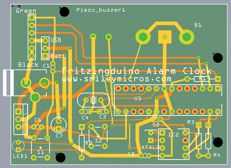
FIGURE 1. Fritzingduino alarm clock PCB layout.
Chicken or egg
One of our goals with the Fritzingduino is to save money. We can have an Arduino compliant system without having to purchase an Arduino and a shield since we can now design our own. To do this, we need an ATmega328 with an Arduino compliant bootloader on it.
You can get a preprogrammed ATmega328 from either AdaFruit or SparkFun for about $6 which is a good deal, all things considered. You can also get raw ATmega328 chips for about $2 and program them yourself.
If you only need a couple of ATmega328s with bootloaders, then buying them preprogrammed makes sense. If you’re going to be doing a bunch of Fritzingduino style projects, you'll want to have your own tools for burning the bootloaders on to the chips.
There are some tools for this that you can purchase, like the Atmel STK500, the Atmel AVRISP, or the Atmel Dragon that you can get from the Atmel web store for $79, $49, and $34, respectively. These are really great prices by the way, but I think you can safely skip the Atmel tools and just acquire a regular Arduino for this project for a couple of reasons.
First and foremost, having a known good Arduino system can radically reduce your debugging efforts as you build Fritzingduino systems. If something works on the 'real' Arduino and doesn't work on your Fritzingduino, it is probably the Fritzingduino's fault.
Second, you can use an Arduino to burn the bootloader into your ATmega328. The store-bought Arduino will pay for itself doing this if you do more than a couple of roll-your-own Arduino projects. So, let's learn how to use an Arduino to program a raw ATmega.
ArduinoISP
The ArduinoISP program was written by Randall Bohn and is included in the Arduino IDE under Examples as shown in Figure 2.
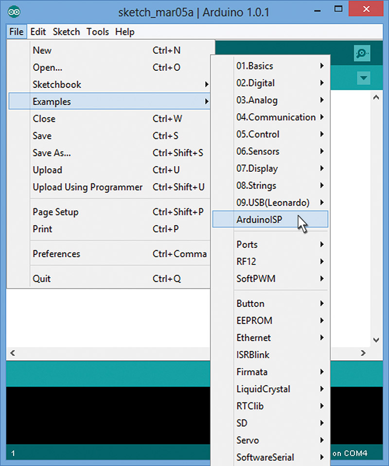
FIGURE 2. ArduinoISP in IDE.
The ATmega328 can be programmed using the ISP (In-System Programmer) feature that allows you to use the SPI (Serial Peripheral Interface) bus to load programs into Flash memory. SPI uses the SS, MOSI, MISO, and SCK lines shown below. Fortunately, the ISP and SPI 'just work,' so we don't need to discuss them in detail here.
Before we learn to use it, let's first look at how to build it.
Build an ArduinoISP Board on an Arduino Proto Shield
The ArduinoISP code is wired to use the Arduino pins as follows:
7 - Programming LED
8 - Error LED
9 - Heartbeat LED
10 - SS
11 - MOSI
12 - MISO
13 - SCK
The ArduinoISP program uses three LEDs to help you see what is going on. These LEDs aren't absolutely necessary to make this project work, but I included them in case you want to watch the action.
Since we are going to build a proto shield board that uses the ArduinoISP, we will need to design our ISP programmer to use these Arduino pins with components on the proto shield. To do that, we need to remember that the Arduino pins are not the same as the ATmega328 pins
When you are wiring an Arduino to an ATmega328, it is easy to get confused. Figure 3 shows an ATmega328 with both the native IC pin numbers and the associated Arduino pin numbers.
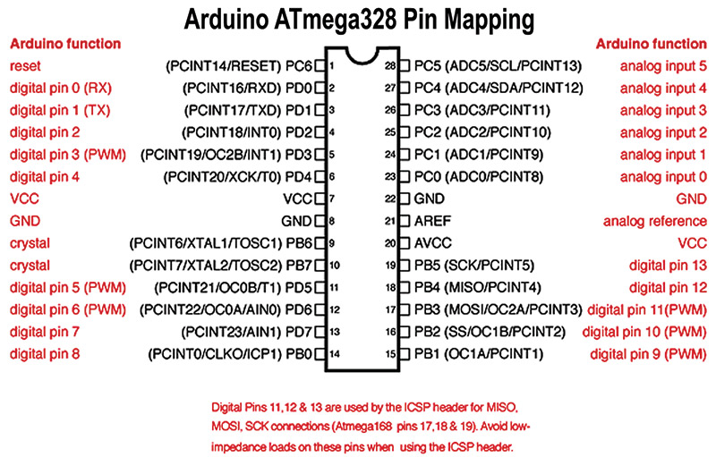
FIGURE 3. Arduino ATmega328 pin mapping.
This diagram may help when you are wiring this project, as will the schematic in Figure 4.
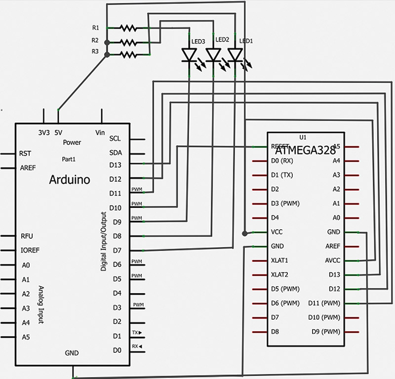
FIGURE 4. ArduinoISP schematic.
You can use this information to wire up an Arduino proto shield breadboard as shown in the Fritzing view in Figure 5.
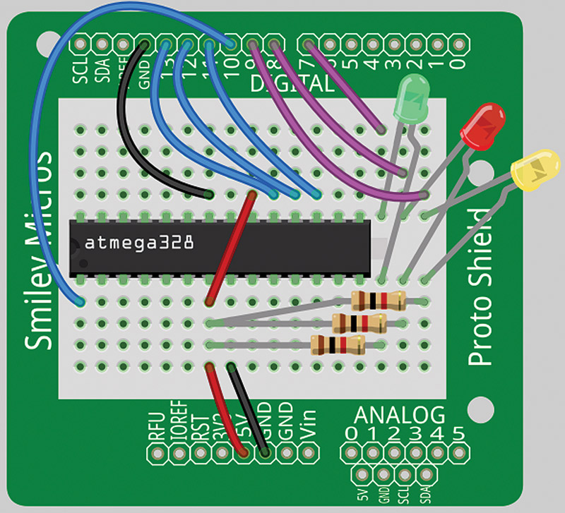
FIGURE 5. Fritzing ArduinoISP with proto shield.
As mentioned, the Fritzing schematic is shown in Figure 4 and the Bill of Materials for this design is listed in Table 1.
| Sch. Part |
Description |
SparkFun Part # |
| Part1 |
Arduino |
DEV-11021 |
| U1 |
ATmega328P |
COM-09061 |
| Q1 |
Crystal 16 MHz |
COM-00536 |
| S1 |
Mini pushbutton |
COM-00097 |
| C1, C2 |
22 pF capacitor |
COM-08571 |
| R1, R1, R3 |
1K ohm resistor |
COM-08980 |
| LED1 |
Red LED |
COM-00533 |
| LED2 |
Yellow LED |
COM-00533 |
| LED3 |
Green LED |
COM-00533 |
TABLE 1. ArduinoISP on a proto shield — Bill of Materials.
In Figure 6, we have a photograph as proof that I really did build this thing on a proto shield breadboard. And, yes, it works.
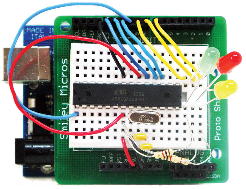
FIGURE 6. ArduinoISP on proto shield breadboard.
Finally, Figure 7 shows the components ported from the breadboard to the proto shield PCB for a more robust system — something you'll need if you use the ArduinoISP a lot.
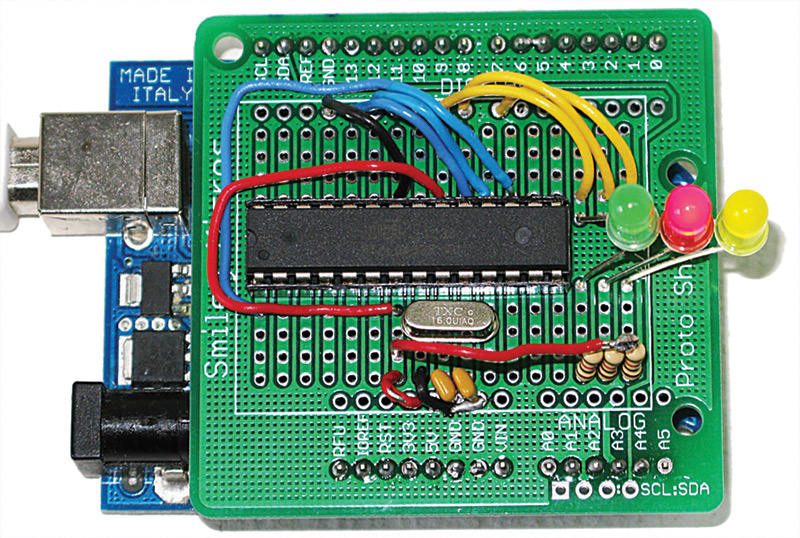
FIGURE 7. ArudinoISP on proto shield PCB.
You should be able to build this circuit following the schematic and the breadboard views. One thing to note is that ICs are shipped with their pins spread wider than the 0.3 spacing of the socket width. This is because they are usually inserted with a tool that squeezes them to the correct width before inserting them in a socket. When you go to put the ATmega328 in the breadboard, you'll find the pins flare out too much. So, very carefully bend them in a smidgen by holding the IC and pushing the pins sideways against a table. This is a craft, not a science. So, experiment carefully. You don't want to bend the pins more than once since they will break.
You can use the Arduino proto shield kit available from the Nuts & Volts web store as the basis for this project. Note that while a single ATmega328P is listed in the BOM, you'll want to get as many ATmega328Ps as you think you'll need for your future Fritzingduino projects.
Design your own ArduinoISP PCB with Fritzing
It is simple enough to generate the PCB files for the ArduinoISP design in Fritzing (shown in Figure 8).
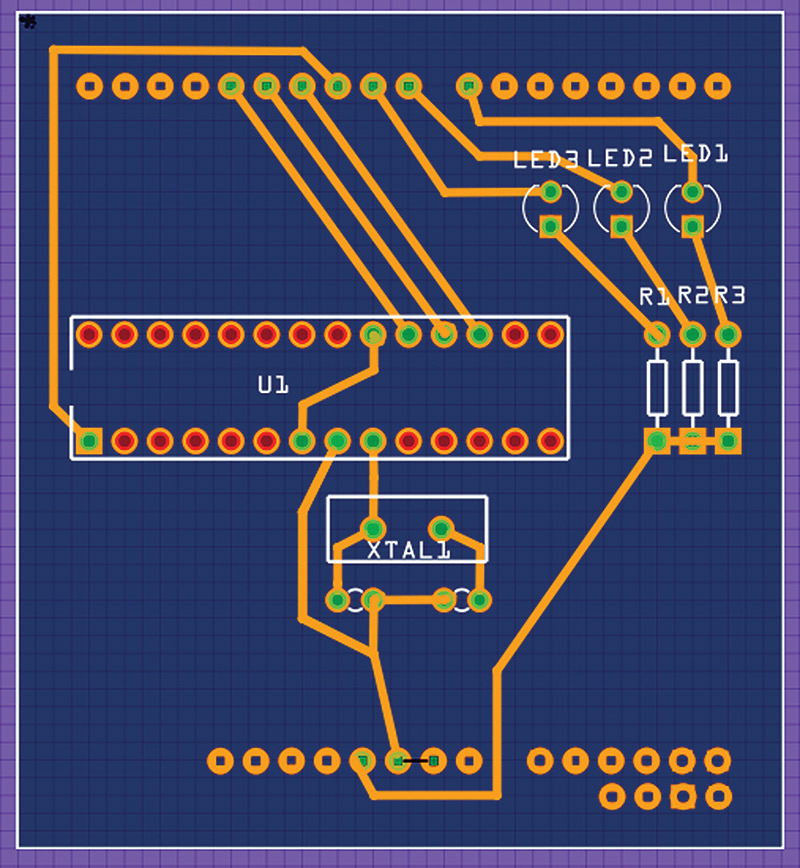
FIGURE 8. ArduinoISP Fritzing PCB view.
I decided not to get a board fabricated for this design since it is simple enough to wire this up on a proto shield PCB as shown back in Figure 7. Plus, I only need one of them.
Using the ArduinoISP
Using the ArduinoISP is a little tricky because we have to keep in mind that we are using the Arduino IDE to upload two separate programs. First, we’ll upload the ArduinoISP code to the Arduino, then we’ll use the Arduino with the ArduinoISP application in it to upload the bootloader to the raw ATmega328 using the ISP wires in our hardware design. Let me repeat. First, upload the ArduinoISP application from the PC to the Arduino. Then, use that application to upload the bootloader from the Arduino to the ATmega328 on the shield. Two steps — clear?
Uploading the ArduinoISP Example
Recall that Figure 2 shows the Arduino IDE with the File/Examples/ArduinoISP highlighted. Click on that file and it will appear in the text editor. You load this to the Arduino like you do any other program. Make sure you've selected your board, and then click on the Upload button. Now it gets tricky.
Uploading the Bootloader to the Raw ATmega328
If you are loading a bootloader to an ATmega328P, you open the Tools/Boards menu item and select an appropriate board such as the 'Arduino Duemilanove with ATmega328.' [Note that you aren't actually using an Arduino Duemilanove — you are just telling that to the IDE so that it will use the bootloader for the ATmega328.] Next — also in the Tools menu — you click on the 'Burn Bootloader' menu item as shown in Figure 9. It may take a minute or two for the bootloader to be uploaded. FYI, the OptiBoot bootloader is the one being uploaded it.
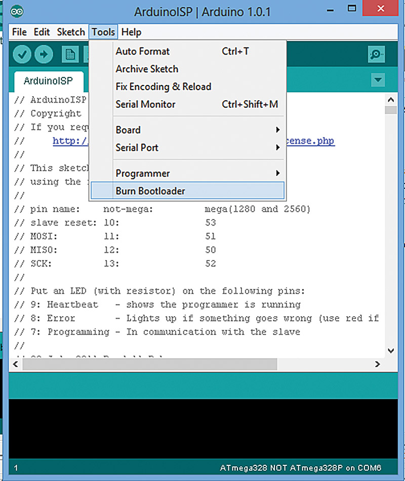
FIGURE 9. FTDI USB to TTL.
Can it be that simple?
Well, let's hope so. Unfortunately for me, I had a bunch of ATmega328s NOT ATmega328Ps, and although the menu items and tutorials for the ArduinoISP say Atmega328, they really mean Atmega328P. In order to use the ATmega328 with no P, you've got to work a bit harder. You must add the ATmega328 to the arduino.conf file located in ...Arduino-x.x/hardware/tools/avr/etc/arduino.conf. You must also add it to the boards.txt file located at: ...arduino-x.x/hardware/Arduino/boards.txt.
Of course, the arduino-x.x is whatever your version of the Arduino IDE is; in my case, it is arduino-1.01 (at the moment). You will add the ATmega328 to these two files by copying blocks of text from a file I've provided and then pasting the blocks to the indicated files.
Open these files in a text editor such as Programmer's Notepad. You will copy a block of code to each of these files and then save them back to their original location. Just to be safe, make a copy of the originals of both files before changing them in case you mess something up.
You can get the two blocks of text from a zip file that you can find at the article link. The file name is 'ArduinoISP Atmega328 files.zip' and it has two text files in it: 'Add to Arduino Conf File.txt' and 'Add to boards dot text.txt.' Open these in your text editor and do like the name says — add them to the indicated files arduino.conf and boards.txt.
One final caveat: This design works for the Atemga328. It may work for other 28-pin ATmegas, but you are going to have to figure that out yourself. There is a bit of Internet chatter on how to modify the original ArduinoISP design and associated files to do this, but since I'm only interested in rolling my own Arduino with the Fritzingduino concept, I'm not interested in pursuing other ATmegas at the moment.
Arduino + Shield = Single PCB
We've discussed the economies of rolling our own Arduino with the Fritzingduino, and we can extend those economies by adding our shield designs to our Fritzingduino so that we have a single PCB and don't need those male/female shield connectors. For example, we've learned to design an alarm clock for an Arduino shield. We could add that shield design to our Fritzingduino and have the whole thing on a single PCB, thus saving us the cost of the Arduino, the shield, and all those headers.
Since we want to get this all on a single PCB, we don't need standard Arduino headers to accommodate a shield — there is no shield. First, we want to create a Fritzingduino base design that has no headers. Figure 10 shows a schematic view for such a design; Figure 11 shows the PCB view.
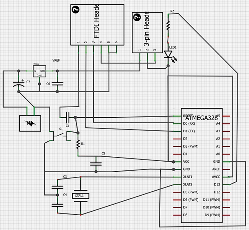
FIGURE 10. Fritzingduino “no shield” schematic view.

FIGURE 11. Fritzingduino “no shield” PCB view.
We call this the Fritzingduino_No_Shield and as you can see, it isn't much use as-is. However, it provides the minimal Arduino clone circuit for our 'Arduino + Shield = Single PCB' equation, so let's save it as Fritzingduino_No_Shield.fzz so that we can reuse it in the '+ Shield' designs.
Fritzingduino + Alarm Clock Shield = FrAC
Battlestar Galactica fans will like our new acronym: FrAC. You'll want to open the Fritzingduino_No_Shield.fzz file and then save it as FrAC.fzz. Next, open the AlarmClock.fzz file shown in Figure 12.
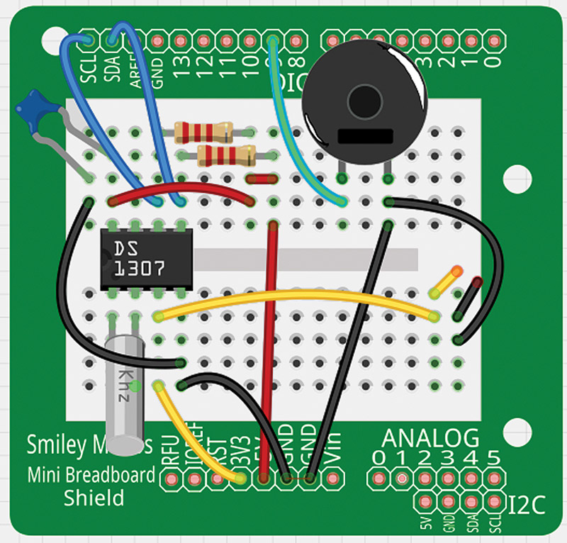
FIGURE 12. Alarm clock on proto shield.
Delete the proto shield and mini breadboard, which will leave you with the components shown in Figure 13.
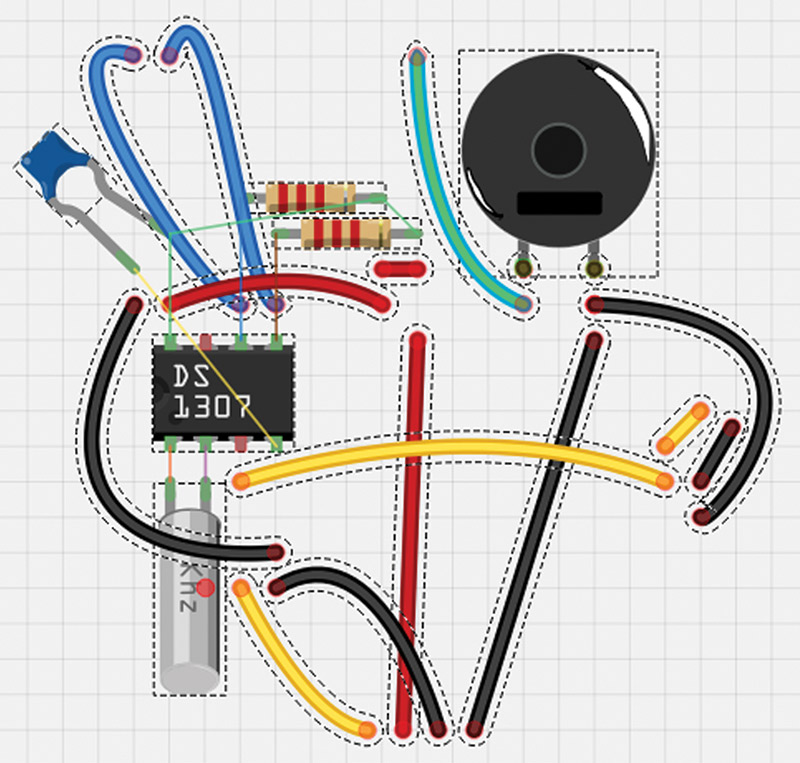
FIGURE 13. Alarm clock parts copied and ready to paste.
Now, do a block copy of these components and open the Fritzingduino project. Paste the components on the breadboard as shown in Figure 14.
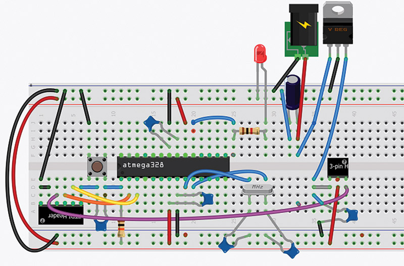
FIGURE 14. Pasted alarm clock on FrAC breadboard.
You'll need to delete and/or move some of the wires, then add the CR1220 battery component as shown in Figure 15.
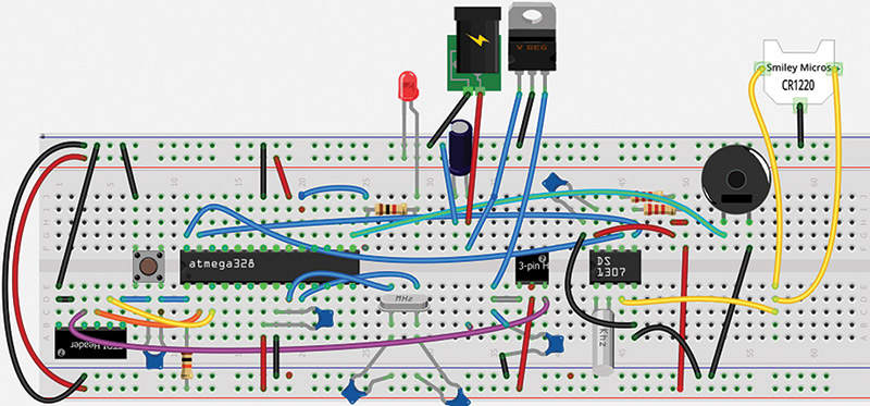
FIGURE 15. FrAC on breadboard.
Note the following when wiring this design:
- Digital pin 9 is PB1 pin 15 on the ATmega328 IC
- SCL is PC5 pin 28
- SDA is PC4 pin 27
You'll get a schematic shown in Figure 16 (of course, you'll need to move the connections around a bit to get this exact image).
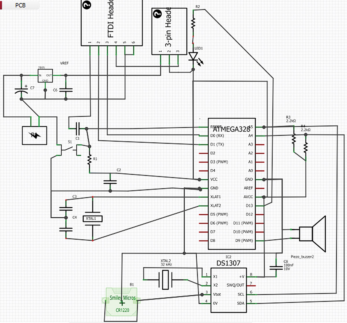
FIGURE 16. FrAC schematic.
The resulting breadboard view is shown back in Figure 1. Now you have combined a minimal Arduino clone with an alarm clock design on a single PCB. Plus, you’ve developed some major prototyping skills in the process.
Go forth and change the world!
Congratulations! You have learned how to use Fritzing with the Arduino to do designs from the prototype stage to production. You can now take that itchy idea that makes you want to scratch your brain and build it on an Arduino proto shield breadboard for preliminary testing. You can then port that design to an Arduino proto shield PCB for a more robust platform. If you want to make more than one, you can then design a PCB that incorporates your idea with the minimum parts for an Arduino compliant clone — all on a single PCB that you can get made through any of the many PCB houses.
When your Kickstarter project gets funded and you get rich off your brain itch, be sure and remember those of us who helped you along the way. NV