Recap
Over the past few episodes, we looked at Digital I/O (DIO). In Part 1, we looked at the software side of DIO as it is done in the Arduino using sequentially numbered pins on the Arduino board. We wrote a library of functions similar to the Arduino DIO library functions but used regular C concepts and tools (AVRStudio, WinAVR, avrdude, avrlibc, etc.).
In Part 2, we saw that the Arduino pins are simple abstractions of the deeper AVR microcontrollers’ concept of ports that are eight-bit arrays of pins. We wrote a library that specifically handles ports and their pins as they are used by raw AVRs.
Then, in part 3, we dropped the abstractions and looked at how DIO is really done in AVRs using the tools available in C, without having to write special libraries to manipulate the ports and pins for DIO. We also went deep into bitwise operators — a painful but necessary bit of learning that is required if you really want to know what C programming is all about (and microcontrollers in general, for that matter). We applied all that to a simple chaser light application.
We are now going to have some fun and apply what we’ve learned about DIO by building something really useful: an open source project that has an LCD and five buttons used to navigate through menus shown on the LCD. You can think of this as a tiny computer terminal and keyboard; a very minimalist (read cheap) one for the AVR. Like other Smiley’s Workshop projects, you can get the parts kit from the Nuts & Volts webstore, as well.
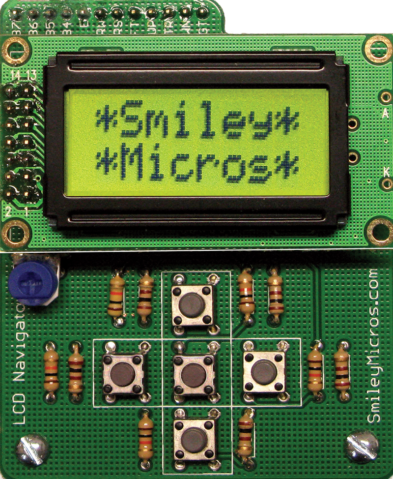
FIGURE 1. LCD Navigator.
Theory Section: Digital I/O in C
The C programming language knows nothing about AVR DIO. C is a hardware independent programming language and runs on any computer. The AVR is a specific computer that does the same sorts of things that are done by other microcontrollers (such as the 8051 or PIC), but it does those things using different hardware. C abstracts the sorts of things you can do with a computer into a higher-level concept that mimics a generic computer. C leaves it up to the compiler to convert the C code into the actual assembly language instructions that a particular computer uses.
C does such a good job of abstracting the way computers work that it is often called a generic assembly language. In early October ‘11, Wired Magazine posted a eulogy to Dennis Ritchie, the father of C:
Ritchie’s running joke was that C had “the power of assembly language and the convenience of ... assembly language.” In other words, he acknowledged that C was a less-than-gorgeous creation that still ran very close to the hardware. Today, it’s considered a low-level language, not high. But Ritchie’s joke didn’t quite do justice to the new language. In offering true data structures, it operated at a level that was just high enough.
Our job is to take the generic things that C can do and use them with the specific things that our AVR can do. Herein lies the rub. AVRs can do a LOT, and as I’ve said before, one of the biggest problems with these things is that they can do so many different things in so many different ways, that it is a chore to figure out which of these many is ‘best’ for a given application. The datasheets are the ultimate resource. Unfortunately, they tell you how to do everything, but don’t give much of a hint as to which things you should choose as the best way to do the task at hand. If you haven’t already done so, I recommend that you get the datasheet for the ATmega328 from www.Atmel.com and skim through it — especially the Digital I/O section. What you’ll notice is that the datasheet offers so much bounty that it is nigh impossible to sort out what we really need to do to get these pins inputting and outputting. Let’s take the bitwise stuff we learned last time and see how that is used to set up the DIO registers.
AVR Registers
The AVR uses eight-bit memory locations called registers to set the functionality of each of its peripheral devices. We’ve sort of hit at AVR registers in other Workshops, but let’s take them on again; this time from the perspective of how we will use them with C and bitwise operators.
Register space is located near the beginning of the AVR memory space. There are a total of 86 registers listed for the ATmega328. They sport names like SPCR, TCNT0, EEARH, EIFR, TIFR2, and so forth. Many of these registers have bits that you set or clear to activate or deactivate a specific AVR function. These bits also have names like TWAM6, COM2B1, ADIE, PCINT22, SP2, ACBG, and so forth. The point I’m making here is that there are hundreds of acronyms used to control the various AVR functions, and neither you nor I have a chance in heck of remembering even a small fraction of them. Thus, it is a painful necessity to get intimate with the datasheet. This pain can be somewhat alleviated by using the Atmel Application notes, forums like www.avrfreaks.net, and tutorials like this one, but ultimately if you are going to get proficient with microcontrollers you have to get real friendly with datasheets.
AVR I/O-Port Registers
If you refer to the I/O-Ports section of the datasheet and look at the Register Description, you’ll see 10 registers listed. We are interested in nine of these registers that are used to control Ports B, C, and D. Each port has a PORTx data register, a DDRx data direction register, and a PINx port input pin address register. The bits of each of these registers maps directly to the external I/O pin on the device as shown in Figure 2.
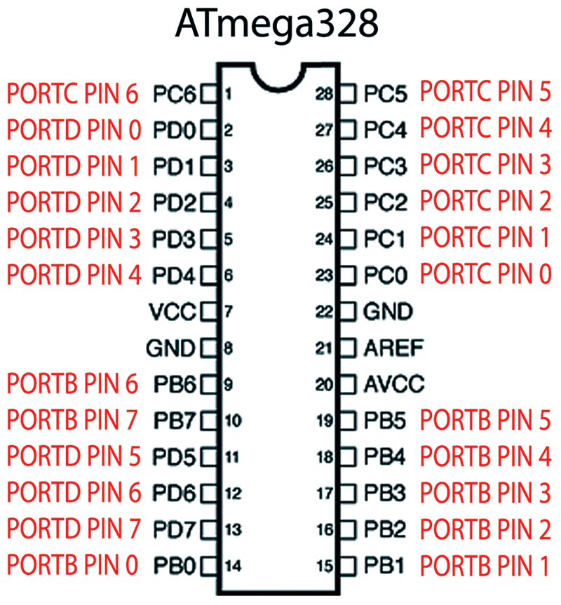
FIGURE 2. ATmega328 port pin mapping.
The PORTx register is used primarily to write data to these pins, the PINx register to read the external state of the pin, and the DDRx to set the direction of the pin. [We discussed the electrical aspects of I/O pins in Part 1 of the DIO series.]
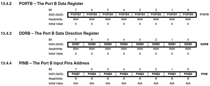
FIGURE 3. Port B registers.
Figure 3 shows these registers in the datasheet; you can see that the individual bits in the registers are logically named after the external pin they represent. Just a note of warning: The PINx register is eight bits just like the PORTx register and will confuse you into thinking that it is somehow related to individual pins. This will be especially true if you are an Ardu-refugee and think in terms of individual pins. It isn’t about individual pins. It is about inputting data from all the pins in a port. Hopefully, this will get clear shortly. Okay, now that you’ve figured out which registers and bits you need to modify and what state to set them, how do you do that in C?
Using AVR Registers in C
You might look at this and think something like, ‘Okay, I want to write a 1 to pin 0 of Port B,’ so I write:
// WRONG!<br />
PORTB0 = 1;
But (you complain), the datasheet says the name of that pin is PORTB0, so how come this doesn’t work? The answer is that because in the avrlibc I/O header, the #define for PORTB0 is 0. So, all you’ve written is: 0 = 1; which it isn’t. All the PORTB0 define does is provide an alias for the pin number which is 0. So, how do you set PORTB0 to 1?
// Right<br />
PORTB |= (1<<PORTB0);
Oh bother! That requires those darn bitwise operators. If you think setting the bit to 1 looks weird, how about clearing it to 0:
// Clear bit to 0<br />
PORTB &= ~(1<<PORTB0);
Yeah, looks sort of like what we learned last time with the bit_set(p,m) and bit_clear(p,m) functions — only now we’ve taken the armor off. This is real C folks. Tighten your seat belts.
Setting the Pins for Input or Output
Since we want to set the pins to output to control our LCD display, we read in the datasheet:
The DDxn bit in the DDRx Register selects the direction of this pin. If DDxn is written logic one, Pxn is configured as an output pin. If DDxn is written logic zero, Pxn is configured as an input pin.
Set the DDRx bit for the pin of interest to 0 and it is an input. Set it to 1 and it is an output. Let’s replace the x with B and see how it is done in our very own port_pin_mode function [int8_t port_pin_mode(uint8_t portx, uint8_t pin, uint8_t mode)] from the elementary digitalio library we discussed in Workshops 40 and 41:
if ( mode == INPUT ) // set DDRB bit to 0<br />
{<br />
    DDRB &= ~(1<<pin);<br />
}<br />
else // ( mode == OUTPUT ) // set DDRB bit to 1<br />
{<br />
    DDRB |= (1<<pin);<br />
}
This would be a good time for you to open up port_pin_mode.c [it is in the avrtoolbox repository] in Programmers Notepad to see the actual implementation. So, memorize this: In 0 out 1. Or I0O1. Or IzeroOone. Or Izzy struck out once. Or just keep the datasheet handy which is what I do because I can never remember which does what.
Despite the datasheet, we see that it really is simple to set up and use digital input and output, so why even bother with the elementary digitalio library functions? Yeah, my point exactly, but since the Arduino has it and one of my goals with the elementary library — as I say elsewhere — is to provide a C transition for Ardu-refugees, I’ve included it in the avrtoolbox. Use it. Look at the source. Then move on.
Moving On
For those who want to use C as is was intended (okay, that’s an opinion), we initialize the LCD control pins by providing aliases for the relevant port, pin, and data direction registers. Then, we use bitwise operators to set them as shown next. To use the LCD, we must set up four data pins and two control pins which we alias to the definitions in the avrlibc input output header file for the ATmega328 (iom328p.h located in your WinAVR directory ..\avr\include\avr\).
// Define the specific ports and pins used for the LCD<br />
#define LCD_D4_PORT PORTD<br />
#define LCD_D4_DDR DDRD<br />
#define LCD_D4_PIN PD5
#define LCD_D5_PORT PORTD<br />
#define LCD_D5_DDR DDRD<br />
#define LCD_D5_PIN PD4
#define LCD_D6_PORT PORTD<br />
#define LCD_D6_DDR DDRD<br />
#define LCD_D6_PIN PD3
#define LCD_D7_PORT PORTD<br />
#define LCD_D7_DDR DDRD<br />
#define LCD_D7_PIN PD2
#define LCD_E_PORT PORTB<br />
#define LCD_E_DDR DDRB<br />
#define LCD_E_PIN PB3
#define LCD_RS_PORT PORTB<br />
#define LCD_RS_DDR DDRB<br />
#define LCD_RS_PIN PB4
To initialize these pins to outputs, we use:
// set LCD DDR pins to 1 for output<br />
LCD_D4_DDR |= (1<<LCD_D4_PIN);<br />
LCD_D5_DDR |= (1<<LCD_D5_PIN);<br />
LCD_D6_DDR |= (1<<LCD_D6_PIN);<br />
LCD_D7_DDR |= LCD_D7_PIN);<br />
LCD_E_DDR |= (1<<LCD_E_PIN);<br />
LCD_RS_DDR |= (1<<LCD_RS_PIN);
Now the registers are set up so that we can control the LCD. Of course, controlling an LCD of the HD44780 variety is moderately complex, but we’ll get to that later.
Lab Section: The LCD Navigator
Assemble the LCD Navigator Projects Kit
The LCD Navigator Projects Kit (shown in Figure 4) is available from the Nuts & Volts webstore.
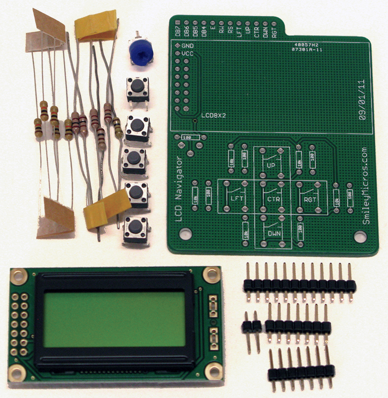
FIGURE 4. LCD Navigator parts kit.
The schematics for this board are shown in Figure 5.
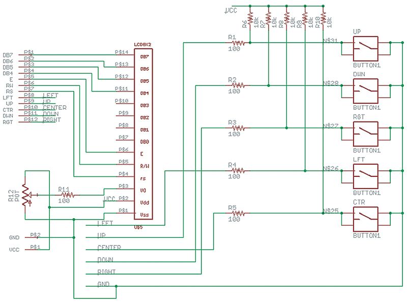
FIGURE 5. LCDNAV schematic.
LCD Hardware: The HD44780 LCD
I read a book (I think it was David Brin’s Practice Effect) where some primitive people found a digital watch with an LCD display. They were amazed that whoever made the thing was able to train all the little black bugs to run around and align themselves in such peculiar patterns. That’s the extent of the detail I’ll give on the underlying technology of LCDs. We’ll concentrate instead on using C to train the little black bugs to do our tricks.
We are lucky since Hitachi developed a simple way to control the LCD that has now become an industry standard for low cost character LCDs: the HD44780 driver/controller chip that you’ll find built into our display. They provide a parallel control interface that can send data in either eight-bit or four-bit chunks, and control the communication with enable and read strobe lines. Since we like to save pins in our AVR designs, we will use the four-bit mode. Of course, all that brain fatiguing stuff we learned about bitwise operators is going to come in handy.
Wiring LCDNAV to the Arduino
Well, after all that preaching to get folks to drill down through the simpler library functions and use the underlying C, we are going to do our first demonstration of the LCD Navigator with the Arduino! Not really. We will only be using the board and do the code in C using AVRStudio, WinAVR, and avrdude. The Arduino is an easy to use development platform and you don’t have to use the Arduino IDE or libraries — you can use it with plain old C. You can see how to wire this up in Figure 6 and Figure 7.
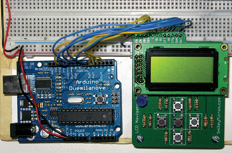
FIGURE 6. LCDNAV with Arduino.
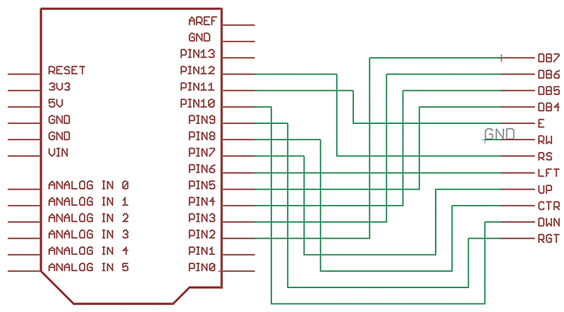
FIGURE 7. LCDNAV wired to Arduino.
LCDNAV wiring to the Arduino is as follows:
- DB7 Pin 2
- DB6 Pin 3
- DB5 Pin 4
- DB4 Pin 5
- E Pin 11
- RW GND
- RS Pin 12
- LFT Pin 6
- UP Pin 7
- CTR Pin 8
- DWN Pin 10
- RGT Pin 9
LCD Software
Using the LCD
We will use our avrtoolbox LCD elementary library which somewhat duplicates the function in the Arduino LiquidCrystal library (but in a more generalized fashion) to use with the regular AVR C tools: AVRStudio, WinAVR, and avrdude. The source code is located in avrtoolbox\libavr\testers\source\lcd_hd44780. I owe a debt to Peter Dannenger for his LCD tutorial on AVRFreaks. His code provided a good starting point for porting the Arduino LiquidCrystal functions [www.avrfreaks.net/index.php?name=PNphpBB2&file=viewtopic&p=828978]. The library has the following functions:
lcd_init()<br />
lcd_clear()<br />
lcd_home()<br />
lcd_set_cursor()<br />
lcd_putc()<br />
lcd_puts()<br />
lcd_puts_p()<br />
lcd_cursor_on()<br />
lcd_cursor_off()<br />
lcd_blink_on()<br />
lcd_blink_off()<br />
lcd_display_on()<br />
lcd_display_off()
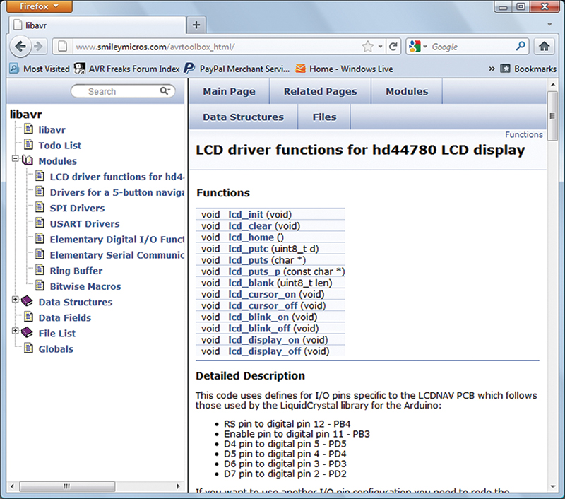
FIGURE 8. LCD documentation in avrtoolbox.
Yes, but can you use it with the Arduino?
I’m really not trying to make folks lives more complex than necessary, but you can use the LCD with the Arduino LiquidCrystal library. It is wired up for it, anyway. The only caveat is that their code is for a 16x2 (16 characters, two lines) LCD while our LCDNAV board uses a 8x2 LCD (it is a lot cheaper). You need to change one line in each example: from lcd.begin(16, 2); to lcd.begin(8, 2);. Note that this doesn’t make a difference in some of the examples since they are hardwired to 16 characters. I suggest sticking with the avrtoolbox code for now.
Well, as usual, we stop in the middle of things. For now, you can wire this up as shown and use it with several applications at https://github.com/nutsvolts/avrtoolbox. These include tester programs for the LCD and Nav button libraries and an LCDNAV_demo program in the avr_application directory. Have fun playing with it and we’ll get more of the details in later Workshops. Next time, we’ll look at the Navigator buttons and a menu application for the LCD Navigator project. NV
Theory is all well and good, but to really learn this stuff you have to get your hands on some tangible items that blink, whirr, and sometimes detonate. As a service for the readers of the Smiley’s Workshop articles, we have simple and inexpensive projects kits available that can help you make it real. You can find these kits (and some darn good books) at the Nuts & Volts Webstore.