Time marches on, and eventually everything goes downhill. That includes me, you, and, surprisingly, most of those capacitors you've been hoarding in your junk box for years, just waiting for a project to put them to use. Why mention capacitors? Because high capacitance types like aluminum electrolytics and tantalums can slowly deteriorate over time. The internal resistance, called “Equivalent Series Resistance” (or ESR) can increase, causing power loss and heating. This can happen if the capacitor has been subjected to electrical stress or elevated temperature, or even while it's just sitting around in storage, not connected to anything.
With the instrument I describe in this article, you can test your store of capacitors or those in some vintage equipment you may be restoring, so you can weed out the ones that may not be up to par. Moreover, this design is easy to build and set up, using only common through-hole parts (no surface-mount devices!) and no microprocessors. In concert with this “retro” approach, the measurement result is displayed on a conventional moving coil panel meter.
I find this device to be a useful gadget to have around my work bench. I have a bunch of capacitors I have accumulated over many years — some of which have been salvaged from old equipment or cycled through several projects. There’s no telling what abuse and degradation they may have suffered, and I definitely don’t want to use a component in my next project that’s going to let me down, no matter how pristine its appearance.
Measuring ESR
As detailed in the sidebar (“What a Capacitor Really Looks Like”), a number of factors contribute to power loss in a capacitor. These losses can be lumped together as ESR, which looks like a small resistance in series with an ideal (lossless) capacitor.
A simple technique for measuring ESR is to supply the capacitor with a known AC current (Icap) at some frequency where the reactance of the capacitor is very low so that the ESR dominates. Measure the resulting AC voltage developed across the capacitor’s terminals (Vcap) and you can find the ESR by dragging out Ohm’s Law:
ESR = Vcap/Icap
This is the basis of the ESR meter I describe in this article. A glance at the equivalent circuit model shown in the sidebar should make this clear.
All capacitors have an inductive component which can possibly interfere with the ESR measurement. In some ESR meters, a square wave or pulsed source is used to test the capacitor, and the resulting inductive spikes can cause an abnormally high ESR reading. Accordingly, I have incorporated a sine wave source into the design to avoid this possibility.
The block diagram in Figure 1 shows that the ESR meter is made up of four fundamental sections:
- A sinusoidal oscillator to supply an AC current to the capacitor under test
- An ESR detector to sense the AC voltage developed across the capacitor
- A meter amplifier and rectifier to display the ESR on a panel meter
- A power converter and voltage regulator section similar to that found in many electronics assemblies
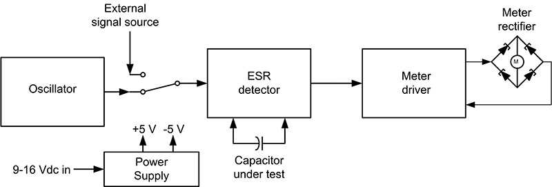
FIGURE 1. Block diagram of the ESR meter.
The full electrical schematic diagram of the ESR meter is shown in Figure 2.
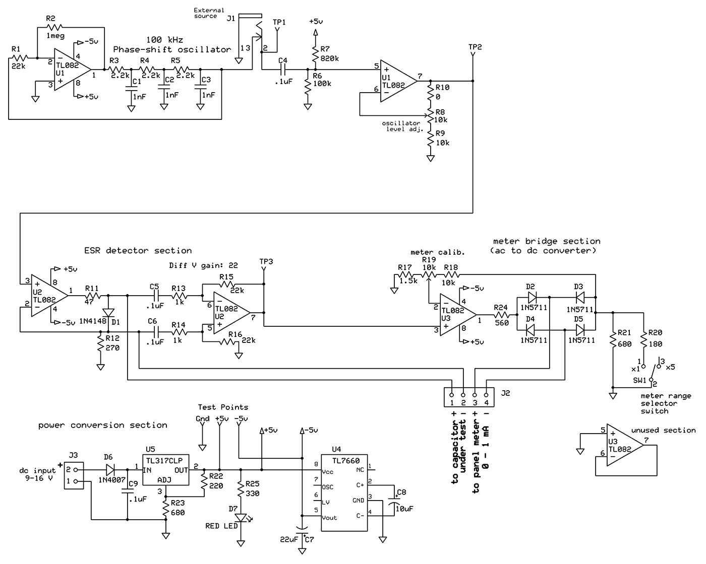
FIGURE 2. Electrical schematic of the ESR meter.
The Oscillator
This supplies the necessary AC signal for driving current through the capacitor being tested. The circuit here runs at approximately 100 kHz, which is an industry standard for making ESR measurements. One section of dual op-amp U1 functions as a phase-shift oscillator in this application. I like this circuit and have used it in several projects. It’s simple to implement and gives a pretty good approximation of a sine wave. It’s ideal for generating a fixed-frequency signal through audio frequencies and beyond, if the requirements are not too demanding.
The other section of U1 acts as a buffer and amplifier. Since the phase-shift oscillator circuit has a moderately high output impedance, this prevents loading of the oscillator circuit. There is also a gain-control potentiometer (R8) which allows you to adjust the level of the 100 kHz signal. Resistors R6 and R7 insert a small DC offset on the AC from the oscillator, so that the signal passed on to the ESR detector has a slight positive bias. Since this signal is applied to the capacitor being tested, some DC bias is required for polarized capacitors.
The circuit path between the oscillator and the buffer amplifier passes through switching front panel 3.5 mm mono jack J1. The jack is wired so that an external AC source plugged in here will interrupt the built-in 100 kHz oscillator and act as a substitute for it. This feature allows you to measure ESR at different frequencies, if you so desire.
If you’re interested in a detailed explanation of how the phase-shift oscillator works, you can find a pdf in the downloads.
The ESR Detector
This is it, folks! This is where most of the action takes place. The first section of op-amp U2 is a voltage-to-current converter where the 100 kHz signal from the oscillator is converted to a current of about 7 mA peak-to-peak. The Capacitor Under Test (CUT) is connected inside the feedback loop of this stage via two front panel binding posts, so the same current flows through the CUT.
Diode D1 — in parallel with the CUT — provides a discharge path for the CUT when you connect it to the ESR meter in case it’s already charged up. In normal operation, the voltage across the CUT is so low that D1 never turns on, so has no effect on the operation of the circuit.
Now that we have established a known AC current through the CUT, it only remains to measure the voltage developed across it. The magnitude of this voltage is directly proportional to the ESR of the CUT. The ESR is usually very low — a few tens of ohms at the most — so this voltage will be down in the millivolt range. The second section of U2 is configured as an AC coupled differential amplifier with a gain of 22, which raises the AC component of the voltage across the CUT to a more convenient level for the meter amplifier stage.
The Meter Amplifier
I wanted the ESR to be displayed on a conventional 0-1 mA moving coil panel meter. (It’s my own personal taste.) For an instrument like this, I just prefer the look of a traditional panel meter over a numerical digital readout. For this to happen, the AC voltage from the ESR detector must be appropriately scaled and converted to a DC current. This is the job of U3 and the diode bridge D2-D5.
The AC from the ESR detector — which represents the level of the ESR we are trying to measure — is fed to op-amp U3. The output of U3 passes through R24, through a bridge circuit composed of Schottky diodes D2-D5, and through current-sensing resistors R20 and R21 to ground. The voltage developed across these resistors is fed back to the inverting input of U3, thus completing the feedback loop.
Within the diode bridge, the AC is rectified and passed through the front panel meter, which responds only to the average (i.e., DC) component. By enclosing the bridge within the op-amp feedback loop, most of the non-linearities inherent when a bridge is used to drive a moving coil meter are removed.
Switch SW1 puts R20 in parallel with R21, reducing the value of the current-sense resistor combination, thus increasing the sensitivity of the meter. With SW1 closed, the full scale sensitivity of the ESR meter is one ohm. With it open, an ESR of five ohms is required to drive the meter to full scale.
The gain of this stage is set by R17, R18, and R19. The latter is a 10K ohm trimmer potentiometer used to set the calibration of the ESR meter after the circuit is built.
If the ESR instrument is powered up with no CUT connected, R24 limits the average current through the panel meter to a maximum value of about 2 mA, thereby making life a bit easier for the meter.
The Power Conversion Section
In this design, I chose to provide both +5V and -5V power buses for the op-amps. This simplifies the circuit design and makes it easier to follow, in my opinion. A single-supply approach would require the additional complication of providing a virtual ground reference throughout the ESR meter. A conventional three-terminal voltage regulator at the input U5 supplies the +5V bus. The -5V bus is easily supplied by U4 — a dandy component from Texas Instruments (TI) that conveniently puts out a DC voltage equal in magnitude to its input, but with a reversed polarity.
Construction
I used the services of ExpressPCB (www.expresspcb.com) to lay out and fabricate the printed circuit board (PCB) for this project. Their standard low cost MiniBoard fits very nicely into a 3 x 4 x 5 inch aluminum enclosure, with plenty of room for a 0-1 mA meter and two binding posts to be mounted on the front panel. The PCB (shown in Figure 3) is laid out with J1 (the external source connector), SW1 (the meter range switch), and D7 (the power-on LED) along one edge.
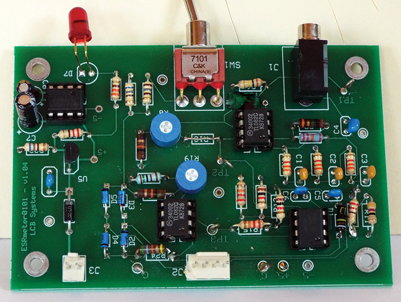
FIGURE 3. Printed circuit board.
The PCB is mounted on 1/4” standoffs on one wall of the enclosure, with appropriate holes bored in the front panel to allow access to these three components. Refer to Figures 4, 5, and 6.

FIGURE 4. ESR meter after calibration. The meter is displaying the value of the one ohm test resistor.
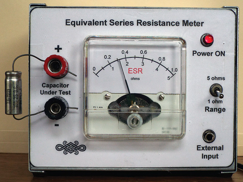
FIGURE 5. The ESR meter in action, reading the ESR of an old (date code 1966) 100 µF tantalum capacitor as 0.3 ohms.
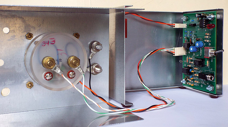
FIGURE 6. Internal wiring, showing the mounting of the circuit board and the cabling to the front and rear panels.
The ExpressPCB schematic and PCB files can be found in the downloads.
Each of the test points for ground — +5V, -5V, TP1, TP2, and TP3 — is made of a short length of solid hook-up wire. One end is soldered into a hole in the PCB, and the free end is formed into a loop for easy grabbing by clip leads or test probes.
Figure 6 is an inside view of the enclosure, showing the internal wiring. Here you can see that connections to the front panel meter and binding posts are brought out from the PCB by four-pin male connector J2, and power from the rear panel via two-pin male connector J3.
Raw DC power (9 to 16 VDC) is supplied through a 2.1 mm coax jack and SPST rocker switch on the rear panel as shown in Figure 7.
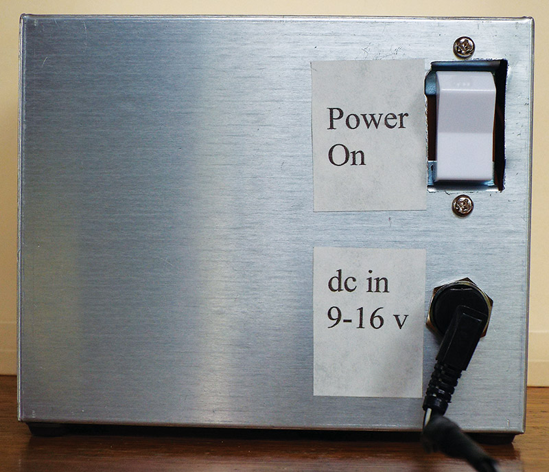
FIGURE 7. Rear panel of the ESR meter.
The current requirement is fairly modest. The whole circuit runs on less than 40 mA. A good quality wall wart type of power source works very well, as does a 9V alkaline battery.
The front panel label sheet and a new face for the panel meter were drawn using Microsoft Visio, printed on heavy paper stock, and glued in place.
Setup and Calibration
There are two adjustment trimmer potentiometers on the circuit board. One (R8) is used to adjust the output of the phase-shift oscillator to about 1.8V peak-to-peak, and the other (R19) sets the meter sensitivity. Full details of this procedure can be found in the downloads at the article link.
Figure 4 shows the result of this setup with a one ohm resistor connected across the CUT binding posts. In Figure 5, a 100 µF tantalum capacitor is being measured for ESR.
Final Notes
Most projects hit a snag or two along the way, and so did this one. If you look carefully, you may spot a small inconsistency between the photo of the printed circuit board in Figure 3 and the ExpressPCB layout file included in the online files. This is the result of an initial design goof on my part, which required me to cut a couple of PCB traces and re-locate components R7 and C4. I revised the PCB layout after the fact, and the ExpressPCB layout file in the downloads has these corrections and agrees with the schematic.
This meter is — in principle — suitable for checking a capacitor’s ESR without removing it from the equipment it’s connected to. The impedance of the surrounding circuitry is normally much higher than the ESR being measured, and the voltage developed across the CUT is quite small: less than 100 millivolts — much too low to switch on any semiconductor junctions in the vicinity. Power to the equipment should be off, of course, and the ESR meter should probably be running off an isolated power source like a 9V battery. I have not tried this type of measurement myself, but I see no reason why it would not be successful.
At this point, I would like to mention some limitations of this instrument, or of almost any ESR meter:
- This meter is not suitable for testing capacitors less than 30 microfarads. If the CUT is too low, the reactance at the measuring frequency becomes significant, resulting in an excessive ESR reading. The solution to this problem is to redesign the system to use a higher frequency. If the need arises, I may try this as a future project.
- A capacitor with an internal short circuit will appear to have a misleadingly low value of ESR, so don’t be fooled (as I have been). Check with a DC ohmmeter if there’s any doubt.
- Because an ESR meter is essentially a low range ohmmeter, long test leads from the CUT can contribute errors to the ESR reading.
- ESR can depend on external factors such as temperature or applied voltage, so a capacitor may behave a bit differently in a real circuit than when it is being tested all by itself.
- Although this unit has some protection built into it, applying a fully charged high value capacitor to the test terminals could damage the circuitry. It’s always a good idea to manually discharge a capacitor before testing.
One final remark: ESR measurement does not usually require a high degree of accuracy, and the meter described in this article should be adequate for routine troubleshooting. In my case, it was very helpful in identifying questionable components, possibly saving me some hair-pulling/teeth-gnashing frustration on a future project. NV
Parts List
| ITEM |
DESCRIPTION |
MFR/PART NUMBER |
| C1, C2, C3 |
1 nF, 100V, ceramic |
Vishay K102K10X7RH5UH5 |
| C4, C5, C6, C9 |
0.1 µF, 50V, ceramic |
Vishay K104K10X7RF5UH5 |
| C7 |
22 µF, 16V, tantalum |
Kemet T350F226K016AT7301 |
| C8 |
10 µF, 35V, tantalum |
Kemet T350G106K035AT7301 |
| D1 |
1N4148 |
|
| D2, D3, D4, D5 |
1N5711 Schottky diode |
|
| D6 |
1N4007 |
|
| D7 |
Red LED |
|
| J1 |
3.5 mm switched jack |
CUI MJ-3502N |
| J2 |
Four-pin male header |
|
| J3 |
Two-pin male header |
|
| R1, R15, R16 |
22K |
|
| R2 |
1 meg |
|
| R3, R4, R5 |
2.2K |
|
| R6 |
100K |
|
| R7 |
820K |
|
| R8, R19 |
10K trimmer |
Bourns 3339P-1-103LF |
| R9, R18 |
10K |
|
| R10 |
0 |
[wire jumper] |
| R11 |
47 |
|
| R12 |
270 |
|
| R22 |
220 |
|
| R13, R14 |
1K |
|
| R17 |
1.5K |
|
| R20 |
180 |
|
| R21, R23 |
680 |
|
| R24 |
560 |
|
| R25 |
330 |
|
| SW1 |
SPDT toggle switch |
C&K 7101SD9ABE |
| TP1, TP2, TP3 |
Test point |
[none] |
| U1, U2, U3 |
Dual op-amp |
Texas Inst. TL082CP |
| U4 |
Voltage inverter |
Texas Inst. TL7660CP |
| U5 |
Adj. voltage regulator |
Texas Inst. TL317CLP |
| (4) Eight-pin DIP IC sockets (optional) |
|
| Panel meter 0-1 mA |
|
| (2) binding posts |
|
| Rocker switch (power switch), SPST |
|
| DC coax jack 2.1 mm |
CUI PJ-011A |
| Printed circuit board 2.5 x 3.8" |
ExpressPCB |
| Enclosure 3 x 4 x 5" |
Hammond Mfg. 1411-LU |
| NOTE: All resistors are axial lead, 1/8 watt or higher. |
What a Capacitor Really Looks Like
Nothing is perfect in this world, and that includes electronic components. Resistors have a little bit of capacitance and inductance; inductors have a smidgeon of resistance; and capacitors have all of the above. Fortunately, most of the time these "parasitic" quantities can be ignored and we can treat the components we use as ideal resistors, inductors, and capacitors.
Notice I said "most of the time." Capacitors — especially large value electrolytics — can suffer from an illusory low value resistor that appears to be in series with an ideal capacitor. This is referred to as the Equivalent Series Resistance (ESR) of the capacitor. It's "illusory" because ESR is not a true resistance; rather, it's the result of a combination of many factors — all of which contribute in some way to power loss in the capacitor. Figure A is the equivalent circuit model of a typical real world capacitor and gives a better picture of what I'm talking about. For high value capacitors and at low frequencies, the stray inductance shown in the model can usually be ignored and the two resistances combined into one.
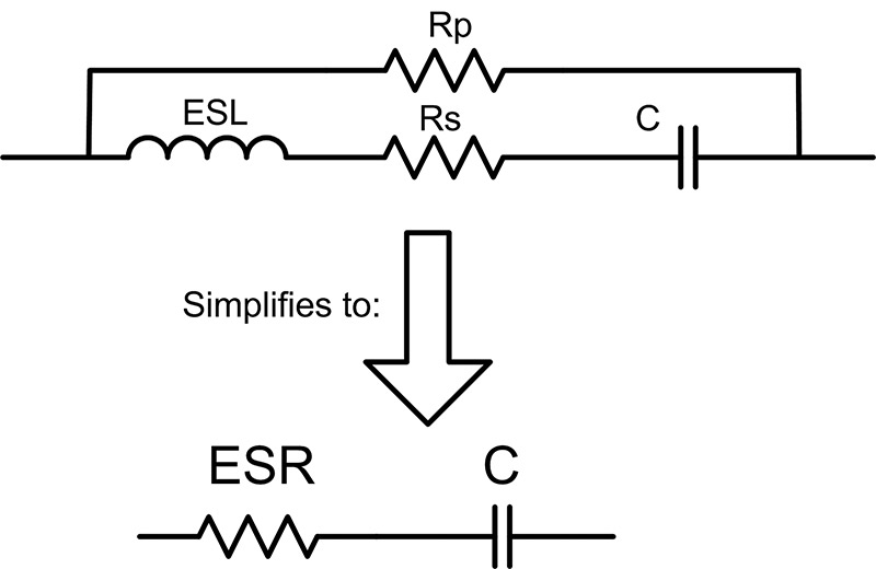
FIGURE A. Capacitor equivalent circuit model (top) and how it simplifies to an ideal capacitor and a single resistance (bottom).
Since you're reading this magazine, you probably already know that every capacitor is basically just a pair of conductors separated by a dielectric. The conductors in a large value electrolytic capacitor are usually strips of foil. The dielectric is an insulating oxide layer formed on one of the strips (the "anode," or positive electrode), plus a liquid or paste electrolyte which acts as the second electrode of the capacitor (the "cathode"). This stuff can be corrosive, so if you have a capacitor which is physically damaged and oozing electrolyte, be careful of getting it on your skin.
Losses in the dielectric plus leakage across the capacitor and resistance in the welds and mechanical crimp contacts to the terminals all contribute to the ESR.
Here's the problem: Over time — especially at elevated temperatures — the liquid electrolyte component of the dielectric dries (or leaks) out. The capacitance may not change very much, but there will be an increase in resistivity; therefore, the ESR rises. To make matters worse, depending on the dielectric substance, the ESR can vary with frequency. This can be a problem if the capacitor must handle substantial alternating current, as in a switching power supply, for example. High ESR combined with high current means extra power dissipated in the capacitor. The resulting temperature rise can cause further degradation and premature failure.
Aluminum electrolytic capacitors are particularly prone to this problem — especially if they've been around for a long time. Solid tantalum capacitors also have ESR problems but to a lesser degree. Small ceramic capacitors are essentially free of this plague.
Downloads
Express PCB File and Schematic
Front Panel Art
Setup and Calibration Procedure
Phase shift osc secrets.pdf