Recap
So far, in our briefly interrupted series on avrtoolbox, we’ve looked at some software engineering principles and applied them to creating the avrtoolbox project on Google Code [http://code.google.com/p/avrtoolbox/]. We’ve learned about creating an open source project using a consistent C programming style, documenting it with doxygen, putting our functions in libraries, and keeping track of the whole thing with a software versioning system. Our last episode taught us about two more software engineering tools: the FRS (Functional Requirements Specification) and the API (Applications Programmer Interface), and applied all that to an elementary serial communications library meant to mimic the kinds of novice-friendly functions we’d find in the Arduino or PBASIC.
The novice-friendly serial library was built on top of two other libraries: one for storing the data (ring buffer) and another for sending and receiving the data (usart). These libraries are not particularly novice-friendly and more like what you’d see in a professional software production environment. This episode will look at ring buffers and at another software engineering tool — the AVRStudio Simulator — that we'll use to test the ring buffer functions. Then next time, we'll look at the AVR usart.
What is a Ring Buffer?
A ring buffer algorithm turns a linear array into a circular array which as you will see in a moment, can be very useful for rapidly storing and retrieving data. A linear array is just a sequence of contiguous memory locations set aside to store data in such a way that you can access the data by using a number indicating its position in the array. For instance, if you had a 64-byte linear array named linArray and wanted to get the 32nd byte, you would use: myByte = linArray[31]. You use 31 instead of 32 because in arrays, we start numbering at 0 rather than 1, meaning we have bytes number 0 to 63 stored for a total of 64 bytes. A ring buffer is a linear array, but we use a special algorithm to make it behave as if it was a ring having neither a beginning nor an end.
Ring buffers are very useful in C programming where we often have a situation where we have two ‘things’ that are trying to deal with the same variable set of data, but are doing so at different rates. For instance, we may want to evaluate a stream of bytes that are coming in over a UART to see if we are receiving a command. However, we may be getting the bytes faster than it can analyze them; so incoming bytes begin to pile up. Another situation could be that we have some code generating data to be transmitted out over a UART but the data is being generated in short spurts faster than the UART can transmit them; so outgoing bytes begin to pile up.
In both cases, we need something analogous to a kind of pipe with a balloon in the middle that expands or contracts as the pressure differs on either end of the pipe. This is actually not such a bad analogy since we immediately see that the balloon must have properties of size and stretchiness that accommodate what comes in and goes out the pipes without overstretching and bursting. Obviously, if we connect a fire hose to one end and a soda straw to the other, that balloon better be large and the fire hose better not be left on too long.
Memory is linear, meaning it is addressed with an integer sequence beginning at 0 and ending at the largest address. We can create a subset of memory as an array that may be allocated anywhere in memory, but the array will keep track of the memory locations as if the first location is address 0. For example, we could allocate a 16-byte array that the compiler/linker would locate beginning at memory location 1000 and ending at memory location 1015. When we address the first element of the array, we use 0, but the underlying code substitutes the address of the first memory element: 1000. This abstraction from the real address means that we can reuse an array in other code on other processors and let the compiler/linker figure out where to put it — a detail that is of no interest to our application. Using our linArray[] example, the first byte at linArray[0] could be at 1000 or 2345 or 54321, but we never see that first address since we are using the linArray[0] as an alias.
We can use this 16-byte array to act as our balloon and handle the overflow. Let’s say the input function is based on an Interrupt Service Routine (ISR) and our function that processes the input data can be interrupted at anytime for more data to be added to the array. Suppose that we have added 10 bytes to our 16-byte array, we start processing them, and are about to process the sixth of the 10 bytes when the ISR receives another 10 bytes to put in the array. Now we have a problem because we have received 20 bytes total and the array is only 16 bytes long. Notice, however, that we have already processed five of the first 10 bytes, so the first five spaces are now of no interest to us and can be considered ‘empty.’ We thus have five empty spaces at the start of the array and eight empty spaces at the end of the array for a total of 13 available spaces, but they are not contiguous. We could go ahead and do this the hard way and use our array as a linear array where the ISR copies the five oldest unprocessed bytes from their locations to the beginning of the array, then follows them with the newly received 10 bytes, leaving the total of 15 unprocessed bytes in the array in the proper order beginning at the start of the array.
Using this ‘hard way’ technique, we will have to set some kind of message to inform any function using the array that the first unprocessed byte has been moved to 0. The user will have to read the message and (in the case above) know that the next byte to examine is not the sixth which it was about to work on, but the first. This shifting of byte and processing of flags is complex and time-consuming, but thankfully the ring buffer concept provides a much easier way to accomplish the task without having to move the data.
Instead of moving the data, we keep two indexes: one pointing to the next location to store data from (head index) and the other pointing to the next location to read data from (tail index). The ring algorithm is more difficult to understand, but it is much more efficient for the machine.
Let’s visualize a circular array like a necklace with pearls where each pearl represents a location to store a byte of data. Let’s say we have 16 pearls and we want one process to be storing data for another process to remove — each at its own rate. The process that does the storing will have the address of the ‘first’ input pearl and store data sequentially around the necklace. The storing process needs to remember the location of the first pearl and the number of pearls used to store data. Then, when we want to store a new byte, we can calculate the total number of already stored bytes (length) and get the next storage pearl by adding this length to the first location to get the location for the next empty pearl.
To extend the analogy, let’s say that the pearls are chosen in a clockwise direction, and that storing data turns a pearl black. We can see in Figures 0 through 6 that adding data causes pearls to turn black sequentially in the clockwise direction. For this analogy, we name the location of the next byte memory location to be written (stored) as the Head and the location of the next byte to be read (removed) as the Tail. We add data to the Head and remove data from the Tail.
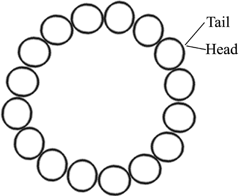
FIGURE 0. Empty.
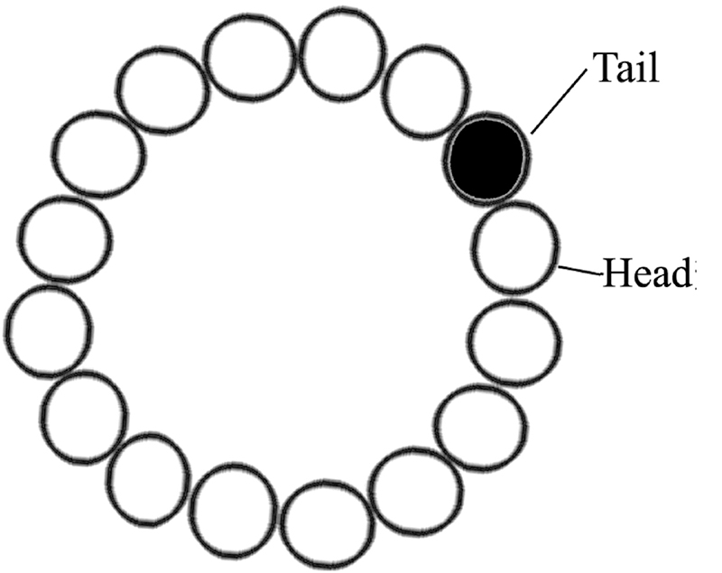
FIGURE 1. First byte stored.
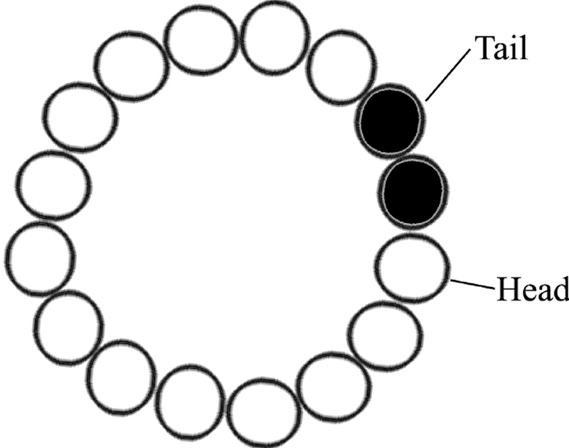
FIGURE 2. Second byte stored.
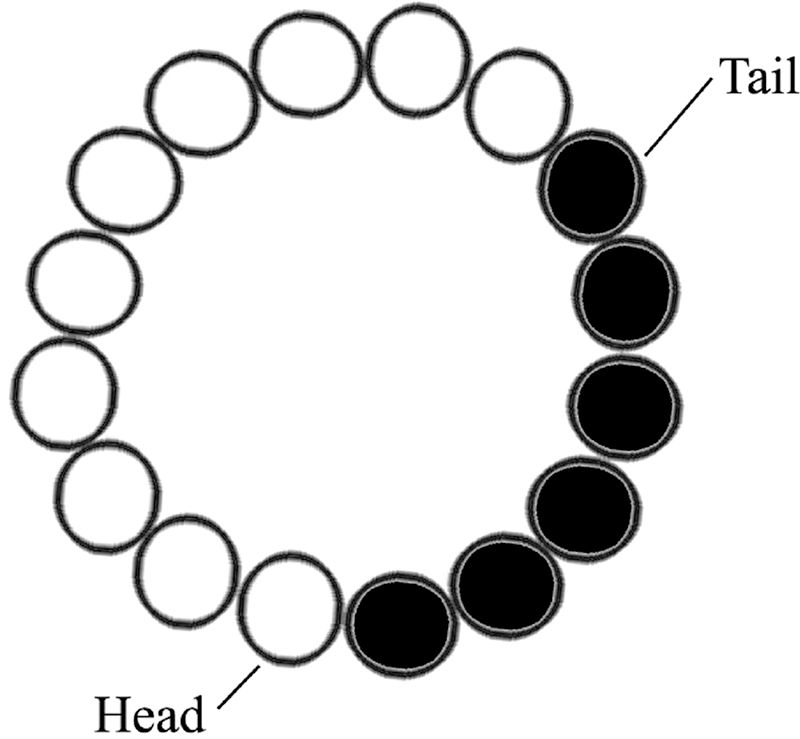
FIGURE 3. Six bytes stored.

FIGURE 4. Three bytes removed.
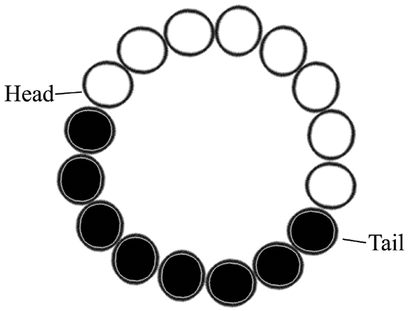
FIGURE 5. Eleven bytes added; three bytes removed.
If the access process is slower than the storing process, then the Head location will grow more distant from the Tail around the circle with the Head and Tail changing as the data is added or withdrawn. However, the Head is equal to the Tail both when the buffer is empty or full, so we have to look at the count to see which is the case. If the buffer is empty, it’s no problem since all that means is that you’ve caught up. However, if the buffer is full as shown in Figure 6, you may have a problem and you may start overwriting data that you haven’t read yet. This is not something that you want to happen. Such a condition won’t hurt so much if the streaming data is audio output and only happens occasionally, in which case the listener may hear a glitch, but if the data is for monitoring the core temperature of a nuclear reactor, well ...
To solve this problem, the storing function must monitor the indexes and the count, and be able to respond intelligently if things are getting out of hand. For instance, if you are receiving bytes from a PC via the UART and the buffer fills up, then you’ll want to use a communication protocol allowing it to tell the PC to hold off for a while.
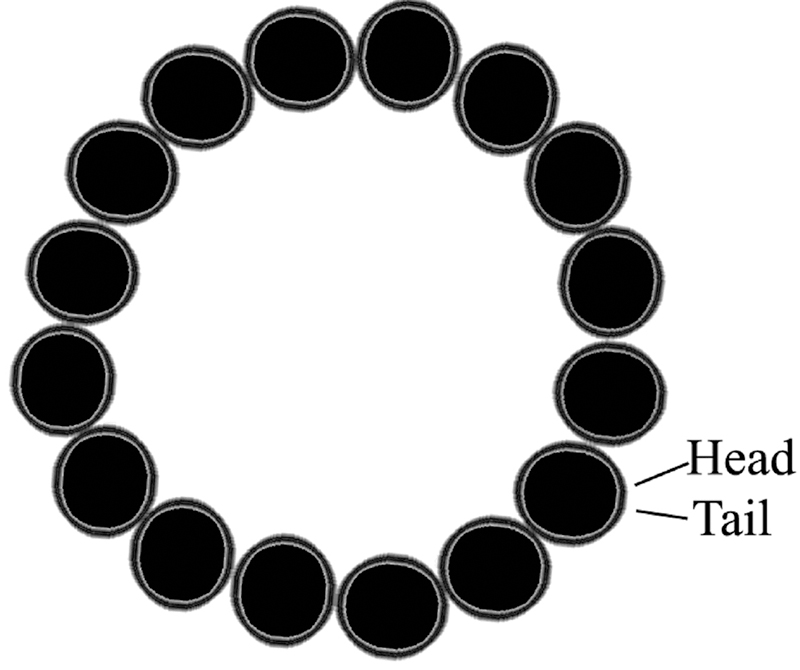
FIGURE 6. Uh oh, 16 added; none removed.
You can lessen the likelihood of this error occurring by increasing the amount of RAM available for the buffer. However, since RAM is precious on microcontrollers, we have to make a trade-off of costs and make a judgment call on how large to make a ring buffer.
Also note that while it is technically feasible to dynamically allocate buffers at run-time using the C malloc() function, eight-bit microcontroller developers aware of RAM limitations rarely do this. So, we will not. We will allocate the buffers when we design the code and make our size decision then.
Ring Buffer Functional Requirements Specification
Ring buffer data type: ring_t will be a data type that will hold a pointer to the buffer, the size of the buffer, the Head index, the Tail index, and the data count.
Ring buffer initialization function: ring_init() will initialize a ring buffer based on receiving a pointer to a ring_t structure — a pointer to a buffer created by the calling function that is of the size provided.
Ring add to buffer function: ring_add() will add a byte at the next available space in the buffer.
Ring remove from buffer function: ring_remove() will remove a byte from the oldest valid location in the buffer.
Ring peek at buffer function: ring_peek() will read an uint8_t ‘count’ number of bytes from the ring buffer into a new buffer provided as a parameter without removing any of the values read from the ring buffer. It will return the number of bytes actually read.
Ring clear function: ring_clear() will set the Tail equal to the Head and load 0 into all buffer positions.
Ring Buffer Applications Programming Interface
ring_t
Description: ring_t is a structure that holds data required to create and manage the ring buffer.
typedef uint16_t ring_index_t;<br />
typedef uint8_t *ring_buffer_t;<br />
typedef uint8_t ring_count_t;<br />
typedef uint8_t ring_size_t;<br />
typedef struct<br />
{<br />
    ring_buffer_t buffer;<br />
    ring_size_t size;<br />
    ring_index_t head_index;<br />
    ring_index_t tail_index;<br />
    ring_count_t count;<br />
} ring_t;
ring_init()
Description: Sets up the ring buffer with ring_t parameters. The clear command is also called to set 0 values within the ring buffer functions.
Syntax: bool ring_init(ring_t *r, ring_buffer_t buffer, ring_size_t size)
Parameters:
ring_t *r: A pointer to a ring_t structure.
ring_buffer_t buffer: A pointer to buffer what you want to use for the ring buffer.
ring_size_t size: Size in bytes of the buffer; must be equal to or greater than two. The actual amount of storage available in the ring buffer is size -1.
Returns: Boolean true if the buffer was created; false otherwise.
Example:
void setup()<br />
{<br />
    // Initialize the ring buffer<br />
    if(!ring_init(ring_t *r, ring_buffer_t<br />
    buffer, ring_size_t size))<br />
    {<br />
        // Buffer not intitialized so<br />
        // handle the error<br />
    }<br />
    <br />
// Okay to use the buffer<br />
}
ring_add()
Description: Adds a byte of data to the ring buffer.
Syntax: bool ring_add(ring_t *r, uint8_t data)
Parameters:
ring_t *r: A pointer to a ring_t structure.
Data: An eight-bit byte of data to add to the buffer.
Returns: Boolean true if the byte was added; false otherwise.
Example:
// receive_ring structure defined elsewhere<br />
bool put_byte(uint8_t b)<br />
{<br />
    return(ring_add(&receive_ring, b));<br />
}
ring_remove()
Description: Removes a byte of data from the ring buffer.
Syntax: uint8_t ring_remove(ring_t *r))
Parameters:
ring_t *r: A pointer to a ring_t structure.
Returns: The byte of data removed.
Example:
// receive_ring structure defined elsewhere<br />
uint8_t get_byte()<br />
{<br />
    return(ring_remove(&receive_ring));<br />
}
ring_peek()
Description: Reads uint8_t count bytes from the ring buffer into a new buffer provided as a parameter without removing any of the values read from the ring buffer. It returns the number of bytes read.
Syntax: uint8_t ring_peek(ring_t *r, uint8_t *buf, uint8_t count)
Parameters:
ring_t *r: A pointer to a ring_t structure.
uint8_t *buff: A pointer to a buffer to hold the data.
uint8_t count: The number of bytes to load from the ring buffer to buf.
Returns: The actual number of bytes read.
Example:
// receive_ring structure defined elsewhere<br />
uint8_t get_bytes(uint8_t *buf, uint8_t<br />
count)<br />
{<br />
    return(ring_peek(&receive_ring, buf,<br />
    count));<br />
}
ring_clear()
Description: Sets all data in the buffer to 0 and sets the Head and Tail indexes to 0.
Syntax: bool ring_clear(ring_t *r)
Parameters: ring_t *r : a pointer to a ring_t structure.
Returns: True if successful; false otherwise.
Example:
void end_this()<br />
{<br />
    ring_clear(&receive_ring);<br />
}
Using AVR Studio Simulator
The AVR Studio Simulator is really great for testing how programs use the AVR memory, but it can be a bit of a pain to use at times. So, if you aren’t already familiar with it, open the AVR Studio Help as shown in Figure 7 and then in the HTML Help file open the Debug section and play around in it as shown in Figure 8.
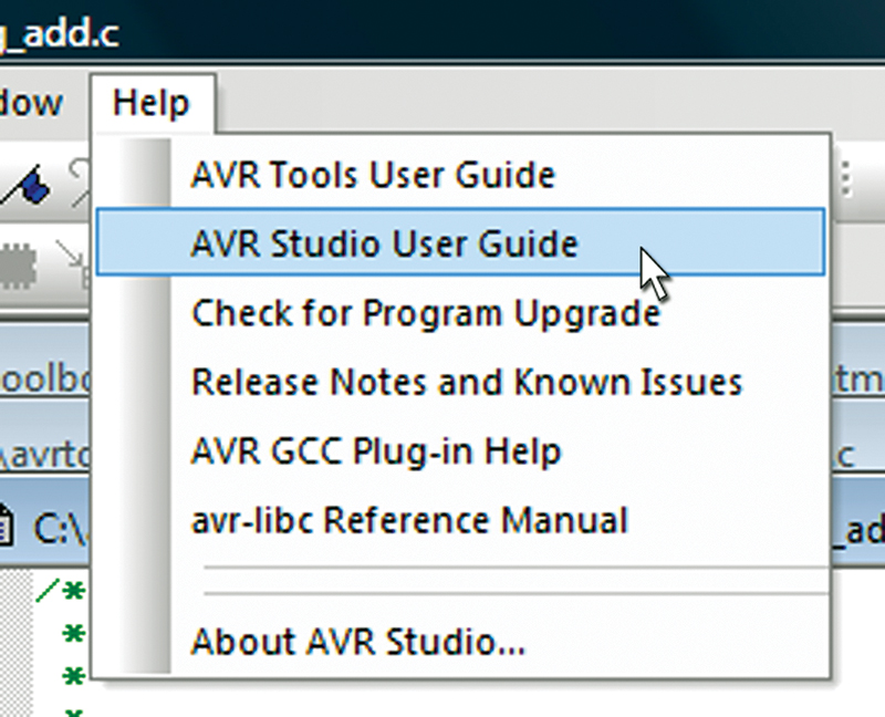
FIGURE 7. AVR Studio Help.
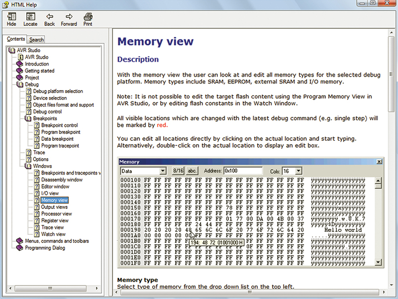
FIGURE 8. Debug Help.
We will mostly be using the Memory View and the Watch View, so read these sections before doing the testing. I found the Simulator to be a bit arcane and balky at times, but with persistence I was able to run all the memory tests in the Ring Buffer Tester. Note that in the following tests you must set the Project Options Optimization to –O0 meaning no optimization since the compiler will look at this code and think that some bits are stupid and remove them. They are stupid, but they are also needed for testing. So, kill the optimizer AND DON’T FORGET to reset the optimization to –Os before compiling any code that you intend to use on a real AVR. Note also that the memory window may not be set to show data when you open it. If anything I do in the tests isn’t entirely clear, I suggest you read the help file. If that doesn’t help, then put on your waders and ask a question on [url=http://www.avrfreaks.net]http://www.avrfreaks.net[/url] using ‘Smiley’s Workshop’ in the title so I might see it.
Testing the Ring Buffer Library
Test 1
We will start out with a simple test just to show that we are initializing and setting the indexes and count correctly. Start with the following code:
#include “C:\avrtoolbox\libavr\source<br />
\general\ring\ring.h”<br />
#include “C:\avrtoolbox\libavr\source<br />
\elementary\serial\serial.h”
#define BUFFER_SIZE 16
static uint8_t array1[BUFFER_SIZE];<br />
static uint8_t array2[BUFFER_SIZE];<br />
static uint8_t array3[BUFFER_SIZE];
int main(void)<br />
{<br />
    // declare three ring buffer data structures<br />
    ring_t ring1;<br />
    ring_t ring2;<br />
    ring_t ring3;<br />
        <br />
    // Create three ring buffers<br />
    ring_init(&ring1, array1, BUFFER_SIZE);<br />
    ring_init(&ring2, array2, BUFFER_SIZE);<br />
    ring_init(&ring3, array3, BUFFER_SIZE);
    // Assign temporary variables so that we can<br />
    // look at them in the Breakpoints and<br />
    // Tracepoint window<br />
    uint16_t volatile temp_head_index = 0;<br />
    uint16_t volatile temp_tail_index = 0;<br />
    uint8_t volatile temp_count = 0;
// Test 1
    // Store six 0x01 bytes in ring 1<br />
    for(uint8_t i = 0; i < 6; i++)<br />
    {<br />
        ring_add(&ring1, 0x01);    <br />
    }<br />
    temp_head_index = ring1.head_index;<br />
    temp_tail_index = ring1.tail_index;<br />
    temp_count = ring1.count;<br />
    <br />
}
We declare three 16-byte arrays, then in the main() functions we declare three ring_t structures. We initialize these ring buffers with the ring_init() function. Next, we create three variables that we will use in our Watch window to observe the ring head_index, tail_index, and count parameters.
Click on the ‘Build and Run’ button as shown in Figure 9.
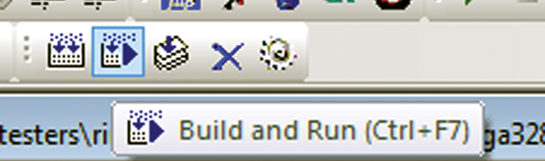
FIGURE 9. Build and Run.
You will notice that the Memory window appears and has some bytes set to zero as shown in Figure 10. These are the locations we have reserved for our buffers.
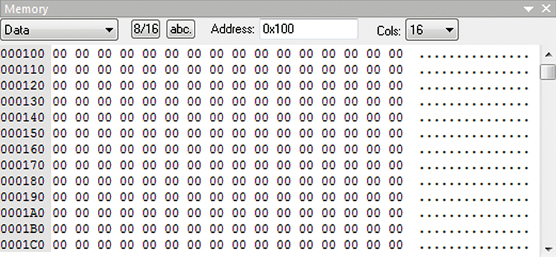
FIGURE 10. Initial Memory.
You can find the starting location of each of the three arrays by putting your cursor on the array name in the code as shown in Figure 11.
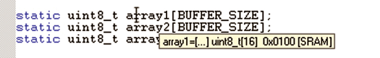
FIGURE 11. array1 size and location.
We see that the arrays’ start addresses are:
array1 – 0x0100<br />
    array2 – 0x0110<br />
    array3 – 0x0120
Place your cursor on the temp_head_index variable, click the right mouse button, and select ‘Add Watch: “temp_head_index” as shown in Figure 12. Then add temp_tail_index and temp_count to the Watch window.
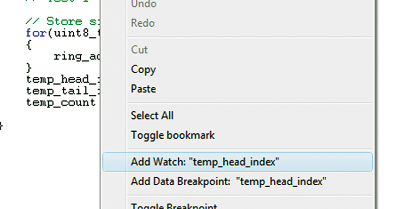
FIGURE 12. Add Watch.
Place the cursor after the last line in the main function, then click on the ‘Run to Cursor’ button as shown in Figure 13.
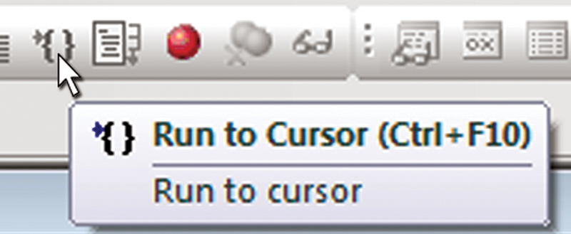
FIGURE 13. Run to Cursor.
We see in Figure 14 that the six bytes beginning at 0x0100 (the start of array1) are changed to 0x01.
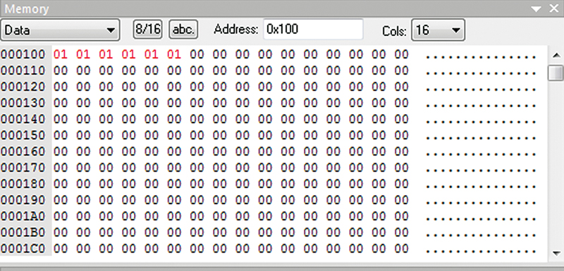
FIGURE 14. Test 1 puts 6 0x01 in array1.
We then see in Figure 15 that the Watch window variables have changed. The variable temp_head_index is 6, temp_tail_index is 0, and temp_count is 6 as we would expect.
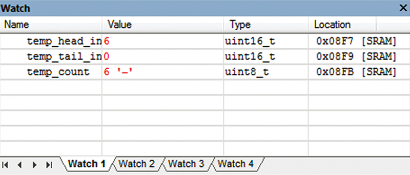
FIGURE 15. Test 1 changes Watch variables.
So, we have now validated that we can create and load one ring buffer.
Test 2
Next, we run the second test by adding the following code and repeating the preceding procedure:
// Test 2<br />
    // First three bytes ‘removed’ to array3<br />
    // Note that the value doesn’t change<br />
    // but the index does change<br />
    for(uint8_t i = 0; i < 3; i++)<br />
    {<br />
       ring_add(&ring3, ring_remove(&ring1));<br />
    }<br />
    temp_head_index = ring1.head_index;<br />
    temp_tail_index = ring1.tail_index;<br />
    temp_count = ring1.count;
In Figure 16, we see that the three bytes have been copied from the first array to the third one located at hex 120. Note also that even though those three bytes were ‘removed’ from the first array, they are still present. This is because only the indexes and counts are changed and the actual data isn’t cleared.
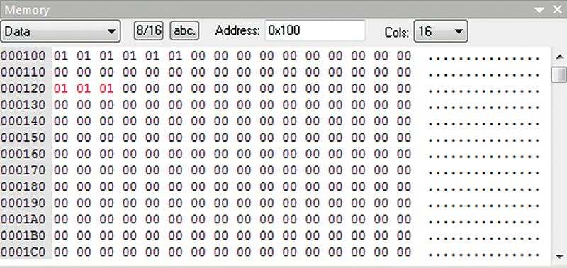
FIGURE 16. Test 2 Memory.
Figure 17 shows the Watch window that now shows that the Head index is still 6, but now the Tail index is 3 since three bytes have been removed; the count is three which is how many bytes remain in the buffer.
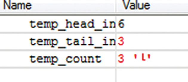
FIGURE 17. Test 2 Watch.
Hey, this is looking like that weird pearl lecture at the beginning of this article, cool …
Test 3
Let’s test the ring_peek() function by filling the ring2 buffer with a sequence of 16 bytes (0x01 to 0x10), then read the eighth and nineth bytes to see if they really are 0x08 and 0x09:
  // Test 3<br />
    // Fill ring2 with sequence of 16 bytes<br />
    // 0x01 to 0x10 and then read the 8th and<br />
    // 9th bytes to see if they really are<br />
    // 0x08 and 0x09<br />
    for(uint8_t i = 1; i <= 16; i++)<br />
    {<br />
        ring_add(&ring2, i);<br />
    }<br />
    uint8_t temp_buf[2];<br />
    uint8_t temp_count;    <br />
    <br />
    ring_peek(&ring2, temp_buf, temp_count)
Placing your cursor over temp_buf as shown in Figure 18 reveals that it is located at 0x08F8 in the SRAM — note, however, that it may be located somewhere else when you do this experiment.
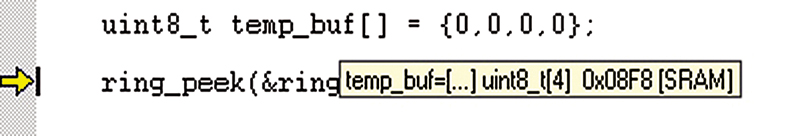
FIGURE 18. temp_buf location.
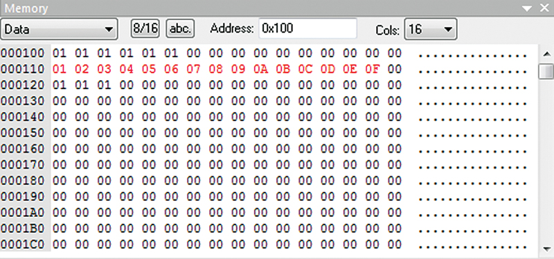
FIGURE 19. Test 3 Part 1.
Figure 19 shows the sequential bytes written in the second array; Figure 20 shows the results of the ring_peek() that loaded the values of the first four into our temporary buffer that begins at 8F8.
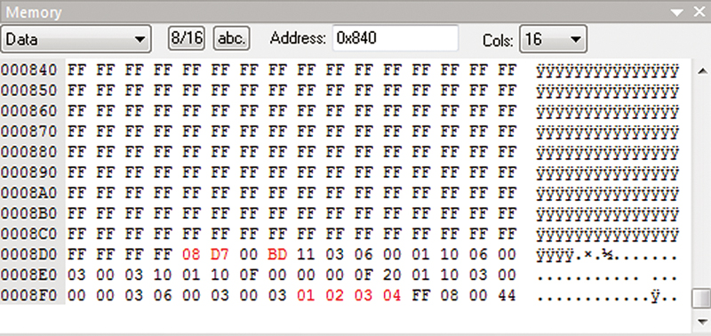
FIGURE 20. Test 3 Part 2.
And Then ...
We have a bunch more tests to run but no more space to show them. I think that if you got this far in the article, you won’t mind finishing the testing without any more training wheels. I’m also sure at some point during all this testing you will scream “IS THIS REALLY NECESSARY!!!” And the answer I’d screamed back atcha is “OF COURSE NOT! YOU CAN TEST THESE FUNCTIONS WHILE DEBUGGING SOME CODE THAT IS ON A TIGHT DEADLINE MONTHS AFTER YOU’VE CREATED THE LIBRARY AND FORGOT HOW IT WORKED!!!” Or, in lowercase, “Nobody said software engineering was easy.”
Since last we looked at avrtoolbox, I’ve redone the directory structure as shown in Figure 21. Now, the top directory is libavr followed by four sub-directories: doc, librarian, source, and testers. The libraries are kept in the librarian directory, one for each of our test platforms (Butterfly, Atmega328 {Arduino board [not IDE]}, and the Atmega644 {BeAVR}).
The testers directory has sub-directories for each module; in this case, ‘ring’ and the code is written so that it references the libraries and header files as they are in the libavr directory tree. Yeah, it is a little complicated at first, but it seems to me the most logical way to keep all this in one place, so I’m sticking with it for a while.
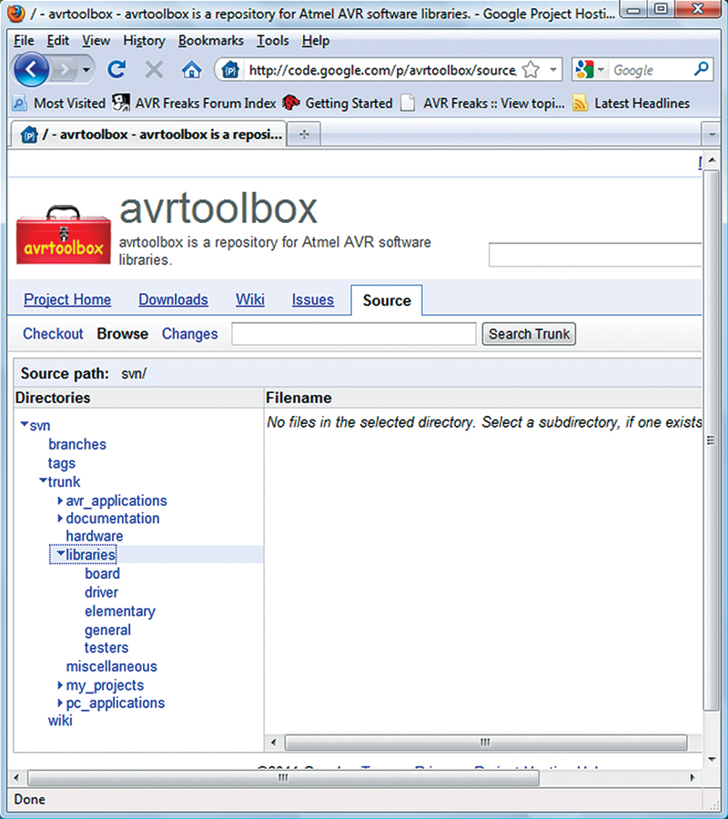
FIGURE 21. avrtoolbox.
Next time, if all goes well, we will continue with avrtoolbox using what we have learned about the ring buffer to apply it to creating an AVR USART library. NV
To get deeper into real C programming and the AVR, try the C Programming book and Butterfly projects kit combo from the Nuts & Volts webstore.