Free energy, aliens, psychic phenomenon ... Why is it that we just can't stop clicking on these things everytime we see them on the net?
I think that the answer is pretty simple because whether you love or hate them, they're almost always highly entertaining!

For this article, I am going to focus on real ESP! That is to say, this is an article in which we have "everything strictly phoney."
With April 1st just around the corner, it's my strong suggestion that we dust off the saw in the garage, warm up the soldering iron, and create a project designed to confound, confuse, and even possibly cause concern to all the engineering minds who encounter it! I'm talking about P.T. Barnum's great American pastime: the humbug.
In this article, we'll feature two devices. One is a classic source of circuitry illogic and confusion (and who hasn't been there in the real world) that will cause one of the simplest circuits possible to give “impossible” results.
The other is a simple — yet seemingly incontrovertible — demonstration of both free energy and perpetual motion.
The thinking behind the creation of these devices is addictive! I hope it will spur many thoughts and a little electronic mischief from Nuts & Volts readers. I'm always ready to be humbugged myself, and hope to hear of some of your designs.
Perhaps we could create a running feature for every April Fool’s Day!
The Perplexer
Our first candidate for confusion is the infamous Perplexer circuit. Oddly, I remember seeing one of these in an old electronics magazine from the early 1900s.
The basic gag is simple. A wooden block has a switch, a battery, and a light bulb. All the wires between the components seem to be clearly visible. However, when the switch is closed on the circuit, the light goes off instead of on! Then, when the switch is opened (clearly leaving no electrical path to the bulb) the light comes back on!
Everything is fully inspectable, and the very simplicity of the device is one of the strongest confounding factors in the illusion.
The method is simple, of course, and hidden inside what appears to be a solid wooden block are the real wires that connect to the lamp base. Closing the switch simply shorts the connection!
A wooden block may have been great for the 1900s, but with the amazing components we have today, we are going to take this great little illusion up a huge step! Figure 1 shows my attempt to modernize and (hopefully) improve this classic illusion.
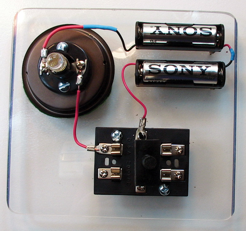
FIGURE 1.
In place of a wooden block (where things could be hidden), we now have our circuit on a completely transparent piece of Plexiglas®, with all the wires and components isolated and completely visible from both sides of the board.
An old style "knife" switch is used (making it obvious contact has been made), and it's even possible for the skeptical to trace the circuit with a VOM — everything will read correctly right to the bulb! Yet, when the switch is thrown the light will extinguish; when the switch is opened, the light will stubbornly stay on. If that isn't enough to cause confusion, the light will return to normal function and operate properly at your command!
The Workings
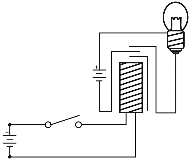
The secret of the new circuit is shown in Schematic 1.
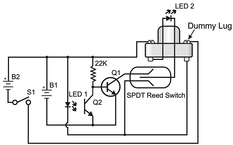
SCHEMATIC 1.
Inside the tiny base hidden under the light bulb is a small lithium cell and basic inverter circuit which actually power and control the light. The function of the circuit is as follows:
- B2 is the pair of AA batteries seen mounted to the Plexiglass, and B1 is the small lithium battery hidden in the lamp base.
- When S1 is closed, LED 1 lights, triggering phototransistor Q2.
Note: You can use an optoisolator for this combo. I happened to use an LED (RadioShack #276-0019) and phototransistor (RadioShack #276-145) which I had on hand. I linked them nose to nose in a piece of heat shrink tubing. Don’t forget the proper current-limiting resistor for the LED if you use an optoisolator.
- Q2 pulls Q1 low, and the light goes out.
- When S1 is again opened, the light will — of course — go back on.
In addition to this, I added an SPDT magnetic reed switch. The reed switch determines whether the circuit will act normally, or in reverse. This is the gimmick that allows you to secretly control the circuit's forward or reverse operation.
Mechanical Modifications
In addition to the circuitry, a few mechanical modifications (the sneaky stuff) are necessary. Figure 2 shows the lamp base disassembled, and the lug leading to the bulb's center terminal is cut (this lug will now be a "dummy" lug which appears to connect to the bulb, but actually does not).
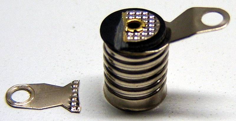
FIGURE 2.
Figure 3 shows the new wiring. The dummy lug is in place, and a wire is secretly run down from the light socket’s center pin.
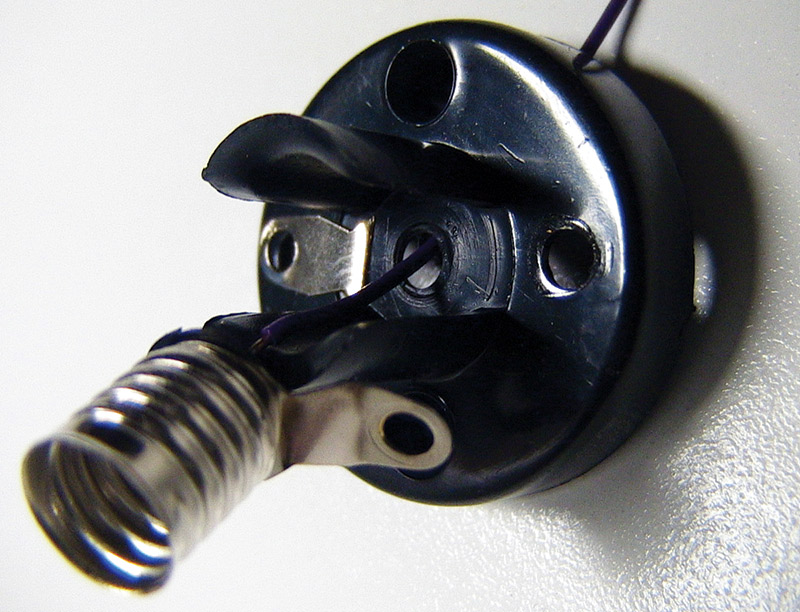
FIGURE 3.
Figure 4 shows the bottom view of the base with all the wires connected.
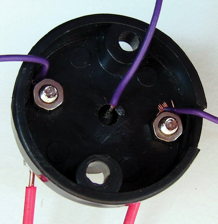
FIGURE 4.
The red wires are the connections which will be visible on top. Figure 5 shows the entire circuit wired to the bulb base.
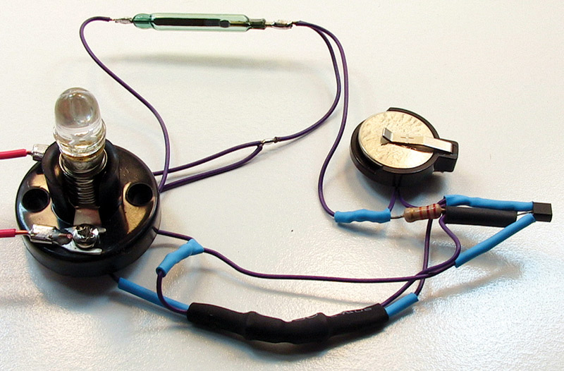
FIGURE 5.
In order to "scrunch" in all the components into a small and irregular area, I used simple point to point wiring. The last modification is to the light bulb itself. Though a light bulb could be used, the draw on the lithium cell would quickly deplete it. It's a simple matter to replace the bulb with a white LED. Figure 6 shows a white LED soldered in place to the bulb base. I completed its assembly by filling the space below the bulb with clear epoxy.
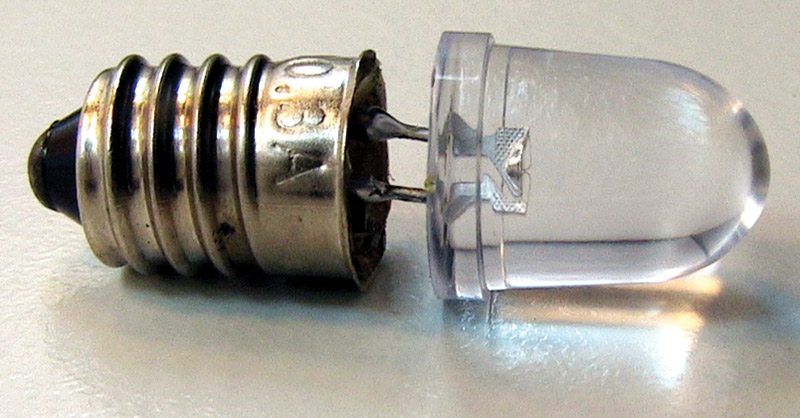
FIGURE 6.
Operation and Thoughts
The circuit works extremely well, and holds up even under close examination. Begin by placing a neodymium magnet under the table where you plan to display your Perplexer. Open S1 and then position the circuit above the magnet's position. The light will come on. Your Perplexer will now function normally (that is to say in reverse) for any who come to try it.
When you want to command it to behave itself (and return to normal switch on, switch off function), simply move the unit a few inches away from the hidden magnet.
Another possible spin on the trick is to remove the lithium battery from the base. In this case, the bulb will not light even if the switch is thrown. Then, at your command (and a subtle move away from the magnet) the light will function normally.
Many modifications are possible. You can forgo the reed switch and simply connect Q1's collector to LED 2's cathode if you'd like the circuit to just operate in reverse at all times. You can also reverse the wires on the reed switch so that the unit operates normally when near the magnet, and in reverse when removed from the magnet. (I think this might actually be a stronger performance set up.)
If you prefer a simplified design, a relay circuit such as that seen in Schematic 2 can be used, keeping in mind the same mechanical modifications mentioned above.
SCHEMATIC 2.
Remember that there is a small consumption on the lithium battery at all times, so it should be removed when not in use for a period of time.
A Perpetual Motion Machine
I've always said that the trickiest thing about building a perpetual motion machine is figuring out where to hide the batteries. Figure 7 shows what I think is a very convincing "perpetual motion" demonstrator. In fact, I’ve already fooled some of the best with the prototype!
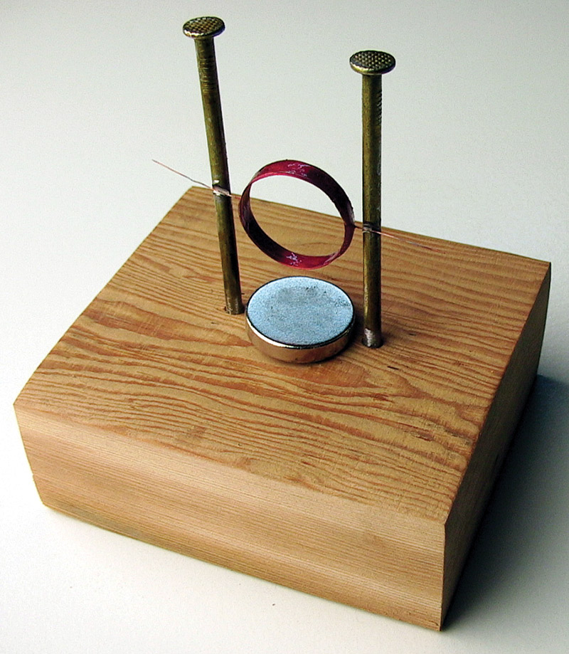
FIGURE 7.
YouTube and the Internet have long been a buzz with free energy and perpetual motion machines. I've noticed that quite a number of these rely on monopole magnets. These are magnets with only a North or South pole which makes attraction without repulsion (and vice versa) possible, and therefore perpetual motion!
Many articles and even some claimed manufacturers have shown up from time to time. The perpetual motion machine here has been designed as a demonstrator of that magical monopole effect. (For those interested, though physics predicts a monopole particle is theoretically possible, it hasn't found one to my knowledge. These “one way” magnets are purely mythological.)
In operation, you tell everyone that you have a monopole magnet and that the currents it generates in a copper winding will create a free energy magnetic field. To demonsrate, place a small winding of copper wire between two nails (that have been pounded into a 2 x 4). Place the magic monopole magnet underneath, and with a woosh it will spin wildly in the cradle with absolutely no power source apparent — except for the magnet.
If you want to really push your luck, you can even claim the device generates a small amount of electricity by touching a VOM to the two nails and reading a generated voltage of 2.4 volts. I’ve had jaws absolutely drop when I did this, and it was all I could do to not encourage investors!
The Workings
The perpetual motion machine here is a very simple homopolar motor which is driven by the Lorentz force. The hidden secret is that two rechargeable batteries are hidden inside the “solid” 2 x 4 and connected to the nails to produce the power. The magnet is normal in every way.
Figure 8 shows a simple 2 x 4 which has been spilt, and a section hollowed out to receive the batteries.

FIGURE 8.
Split the 2 x 4 with a hammer and screwdriver. A messy, uneven split is actually best. Saw away the few inches of the 2 x 4 where the screwdriver left it marks, and you now have a piece ready to go together again with no visible seam!
To attach copper wires to the nails, predrill two holes to tightly fit the nails, insert the copper wires into the holes, and tap the nail into place. The nail will tightly wedge against the copper wires as shown in Figure 9.
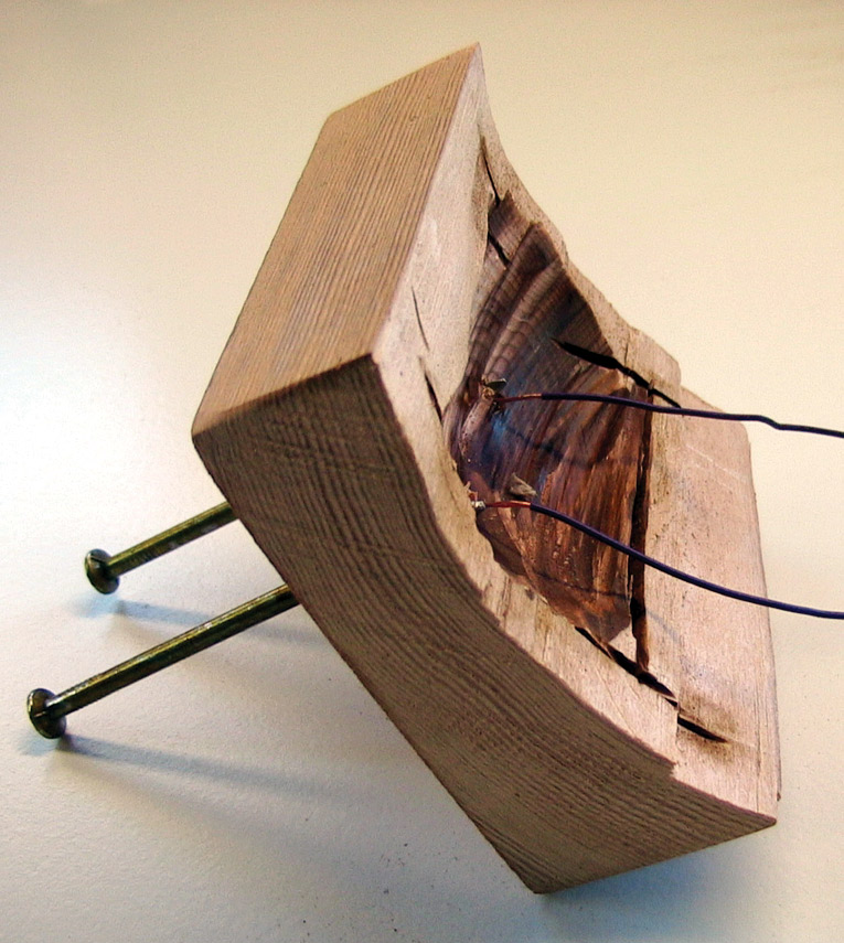
FIGURE 9.
Ideally, use solder tab NiCads, or CAREFULLY solder the wires to any rechargeable AA batteries so they are connected in series; then connect the + and - leads to the nails, respectively. Clamp the 2 x 4 piece back together tightly as seen in Figure 10.

FIGURE 10.
After the glue has dried, give the block a light sanding, and you will have a seamless masterpiece of deception!
Next, wind a few turns of magnetic wire around a form of any kind. Just about any number of turns above 20 will work. I wound my coil to be about an inch in diameter, and used #24 enameled wire. (Many other sizes will work; feel free to experiment.) I coated the magnetic wire with five minute epoxy so it would hold its shape. The resulting coil can be seen in Figure 11.
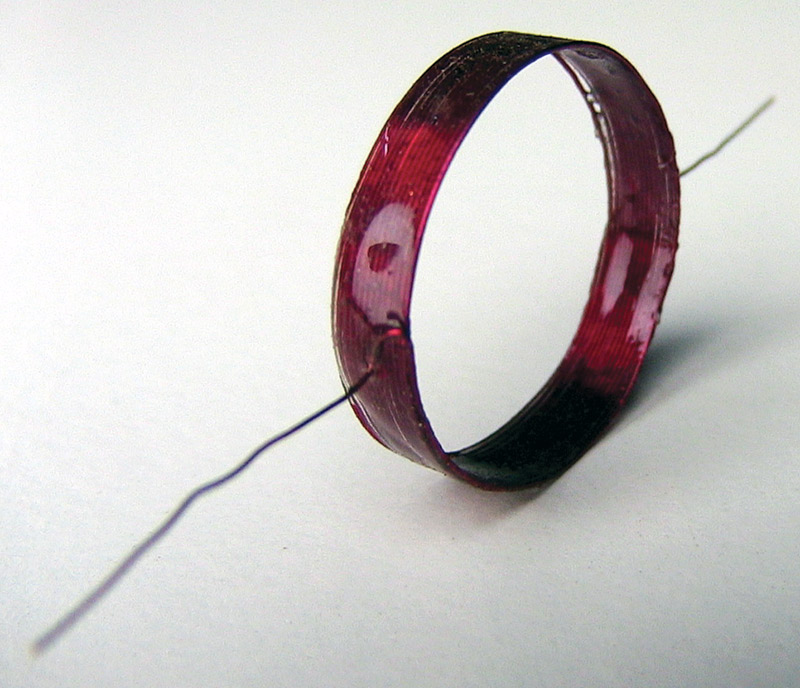
FIGURE 11.
The last step is to create a cradle for the spinning coil to seat in. The easiest way is to attach alligator clips to the nails at an angle that creates a seat. In my case, I simply filed a couple of diagonal slots into the nails as seen in the main photo. Viola! You're ready to demonstrate homopolar magnetics and perpetual motion!
Operation
To demonstrate your device, simply place a neodymium magnet at the base of the nails as shown. The little coil should be well balanced to spin, and the insulation should be stripped off the ends of the wire which touch the nails. As soon as the coil is seated between the nails, it will wobble mysteriously, and then begin spinning at high speed. (It might need a little push to get started.) It really is a little wonder to behold.
I used a 2 x 4 scrap to further the illusion that nothing was being hidden. However, these little motors are so much fun to make and run, that a much nicer piece of wood (such as a trophy base) could be used for permanent displays.
I was also considering nickel-plating my nails to prevent rust, especially in the slots which need to be conductive long term. When perpetual motion no longer occurs on command, simply recharge your batteries through the nails.
Wrap-Up
I'll try to put together a video for Nuts & Volts readers for those who would enjoy seeing both circuits in operation at the article link and at www.noonco.com/perpetual.
Now, the question is should I tip the secret in the video? Or, let those who haven’t read this article wonder?
Happy 1st of April! NV
| PERPLEXER PARTS LIST |
| Item |
Part # |
| R1 22K |
|
| Q1 |
PN3566 |
| Q2 & LED 1 |
See Text |
| S1 Knife Switch |
RadioShack #275-1537 |
| SPDT Magnetic Reed Switch |
|
| LED 2 10 mm White LED |
RadioShack #276-0005 |
| B1 3V Lithium Cell 2032 |
|
| B2 (2) AA batteries |
|
| S1 Knife Switch |
RadioShack #275-1537 |
| Misc. |
| CR2032 Battery Holder |
RadioShack #270-009 |
| Miniature Lamp |
RadioShack #272-1132 |
| Lamp Base |
RadioShack #272-0357 |
| (2) AA Battery Holder |
RadioShack #270-401 |
| Neodymium Magnet 2 x 2 x 1/2 (or larger) |
|
| Plexiglas Scrap |
|
| PERPETUAL MOTION PARTS |
| Neodymium Magnet Circle 1” x 5/16 |
| #24 Magnetic Wire |
| (Many other sizes work for either of these parts.) |