C Programming • Hardware • Projects
Recap
In our last episode, we had the first of a two-part series providing a very convenient way to hook up a serial connection and provide a power supply for use in electronics prototyping on a solderless breadboard. Now, we'll see how to use this for general-purpose input/output to read switches and light LEDs. Then, we'll use a seven-segment LED to make the “World’s Smallest Moving Message Sign.” Finally we will create an Arduino compatible prototype on a breadboard.
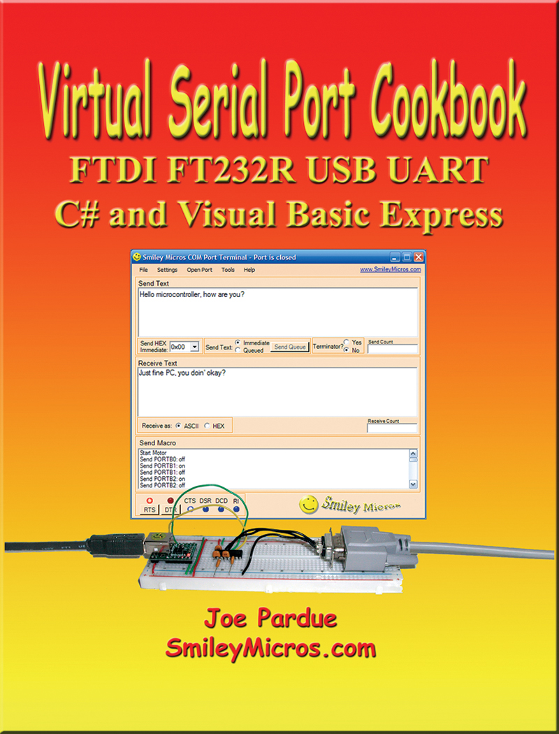
FIGURE 1. Virtual Serial Port Cookbook.
This and the last Workshop are based on the revision of my book Virtual Serial Port Cookbook which is about the FTDI FT232R USB to UART converter that lets folks use their PC USB connection to emulate the much easier to use serial communication port that served our prototyping needs so well for so long. The revision is mainly to incorporate two additional FT232R prototyping boards: the Gravitech board (http://store.gravitech.us/ftusbtouabrb.html – note this is .us not .com) and the Bob-00718 from SparkFun (www.sparkfun.com/products/718).
Last time, we got them set up and did a loopback test using a simple terminal program (appropriately named Simple Terminal). Then, we finished with a working serial connection between our PC and a solderless breadboard, ready for doing some electronics prototyping.
Electronics Prototyping?
You may have noticed that I used ‘Electronics Prototyping’ in the title. Is this really ‘Electronics’ prototyping when it involves a buried microcontroller on the FT232R? Aren’t electronic and microcontrollers really two different things? I think folks tend to think of electronics and microcontrollers as two very different areas of study. Sure, microcontrollers are electronic devices, but there was an analog versus digital mentality that put electronics squarely in the analog arena and microcontrollers in the very different digital arena. But times, they are a changing.
As Moore’s Law has made transistors insanely cheap, we can now throw them at analog problems that once would have been far too expensive to handle with digital circuits. One example of this is the LM555 timer ‘electronic’ device, probably the most venerable circuit employed in every introductory electronics course.
Not long ago, I was designing an IR communications remote control (yeah, like those entertainment center remotes stuck in your couch cushions) and mid design I realized that I could get an eight-pin AVR microcontroller for about the same price as a ‘555, and that the AVR could do everything a 555 can do and a lot more. Epiphany! Not only is the price for the ICs about the same, but I also didn’t need to use the external components for the 555, allowing me to eliminate parts and reduce board space. AND I had the flexibility of a programmable device!
Another example of analog being overwhelmed by digital is a recent project where I wanted to do some radio communications and I started seeing these radio ICs that seem to have all the analog magic hidden under a black blob of epoxy. The interface seemed suspiciously like they had a microcontroller buried in there somewhere. Has computing become so cheap that analog electronics is being subsumed into digital microcontrollers? Frankly, this has kind of snuck up on me so I’ll have to do a lot more studying before running around yelling “analog is dead,” but I’m pretty sure I can at least mumble “analog ain’t as healthy as it used to be.”
Where this leads is the concept that contemporary electronics prototyping is no longer as much about analog design as it is about throwing cheap transistors at the problem and purchasing off-the-shelf integrated solutions that mix the analog with digital control in a single chip. So, electronics prototyping now becomes as much about computers as it is about circuits.
Bit-Banging — Hardware Experiments
Despite the pin labels on your FT232R PCB, those pins lead a double life as shown in Figure 2.
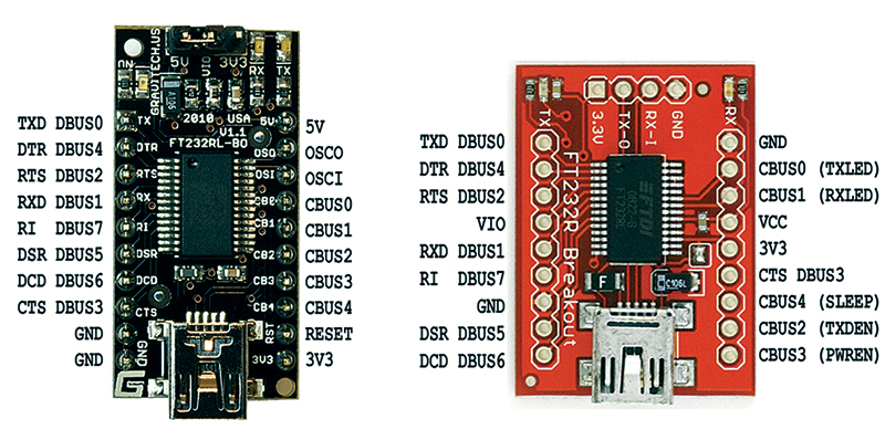
FIGURE 2. Board pin-outs.
The D bus pins each have a modem pin alias that they use when sneaking around in the underworld of serial communications — for instance, DBUS0 is also known as TXD.
For these bit-bang experiments, we will use the D bus names DBUS0 to DBUS7. Note that the pins are scattered about on the PCBs in no logical order. This wasn’t done just to confuse you. (Really.) Do you remember the discussion about Funky Logic? Well, now is when the funk splats on the wall, so be prepared for a mess.
Output
We will test bit-banged output using LEDs that have their anodes tied to Vcc via 2.2K ohm resistors, and their cathodes tied to a FT232R pin as shown in Figure 3. When the pin is high, no current flows and the LED is off. When the pin is low, current flows and the LED is on.
The fun starts when we try to remember the true/false logic of which bit state is low and which is high since it differs for the D bus and the C bus. The D bus On state is low and the C bus On bit state is high — confusing, yes, but just remember it.
Output On The D Bus
Wire your FT232R PCB for five volts as shown in Smiley’s Workshop 33, then wire up the DIP switch, eight LEDs, and 2.2K resistors as shown in Figure 3, depending on which board you are using. Figure 4 shows the SparkFun unit and Figure 5 shows the Gravitech setup.

FIGURE 3. Schematic DBUS to LEDs.
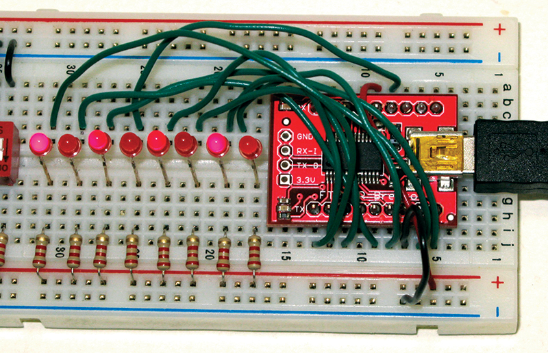
FIGURE 4. SparkFun FT232R PCB wired up to eight LEDs.
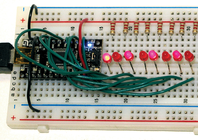
FIGURE 5. Gravitech FT232R PCB wired up to eight LEDs.
We will test this prototype with a bit-bang test program I wrote in C# .NET that you can get from the article downloads. Open the bit-bang test program and select the FT232R PCB. Now, if you’ve done everything right (and if you are like me you haven’t), when you flip the virtual switches as shown in Figure 6, you will output 0xAA which will then light up the LEDs in a 0x55 pattern (extra credit if you remember why).
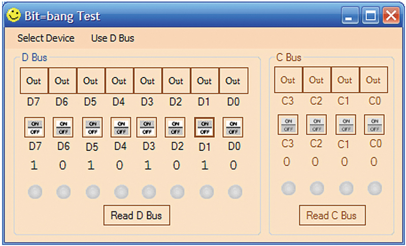
FIGURE 6. Bit-bang Test output 0x55 on Dbus.
Output On The C Bus
To demonstrate the C bus, rewire the circuits shown in Figures 4 or 5 as shown in Figure 7.
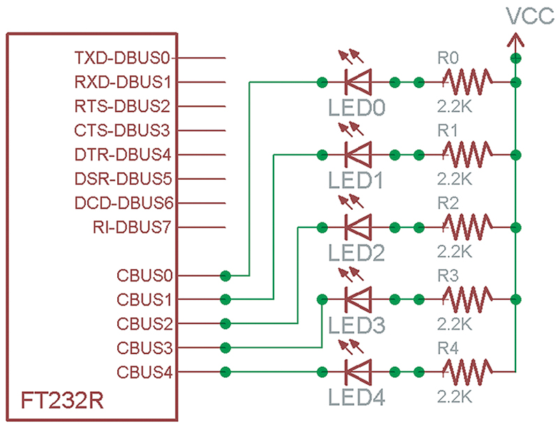
FIGURE 7. Schematic CBUS to LEDs.
Toggle the ‘Use D Bus’ menu item so that it reads ‘Use C Bus’. The D bus groupBox will be disabled while the C bus groupBox will be enabled, as shown in Figure 10. This should behave exactly as the D bus demo.
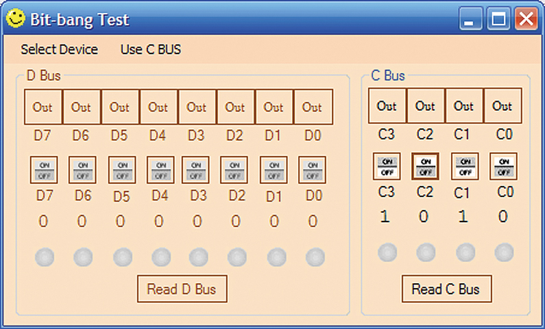
FIGURE 8. Bit-bang test.
Input
Before beginning this, note that the eight-position DIP switch is numbered left to right (1, 2, 3, 4, 5, 6, 7, 8). We will ignore those numbers and think of it as a binary sequence with the least bit on the right, and thus numbered 7, 6, 5, 4, 3, 2, 1, 0. This will further our confusion, making this experiment even more like the real world.
We will wire the pins to a 2.2K ohm resistor to ground and to the switch that when open will connect the pin directly to ground, and when closed will connect the pin to VCC.
Input On The D Bus
Rewire the breadboard according to the Figure 9 schematic which should look something like Figures 10 or 11.
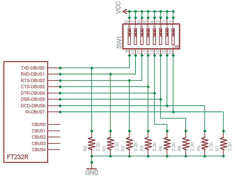
FIGURE 9. Schematic DBUS to DIP switch.
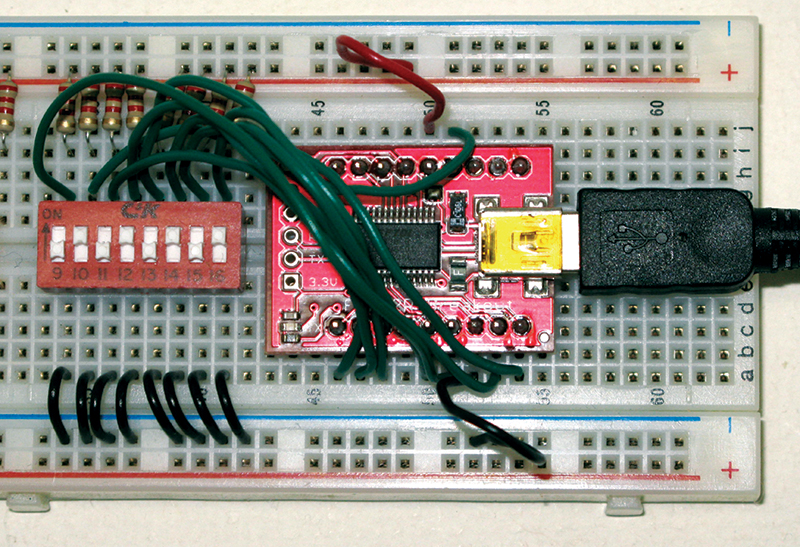
FIGURE 10. SparkFun FT232R PCB wired up for eight-position DIP switch.
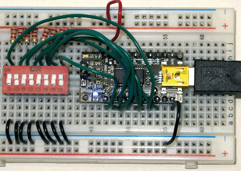
FIGURE 11. Gravitech FT232R PCB wired up for eight-position DIP switch.
In the bit-bang test program, click on all the buttons on the top row of the D bus groupBox to convert each pin to an input as shown in Figure 12.

FIGURE 12. Bit-bang test read Dbus.
Input On The C Bus
By now you know the drill, so wire up things for the C bus and run the test as shown in Figures 13 and 14.
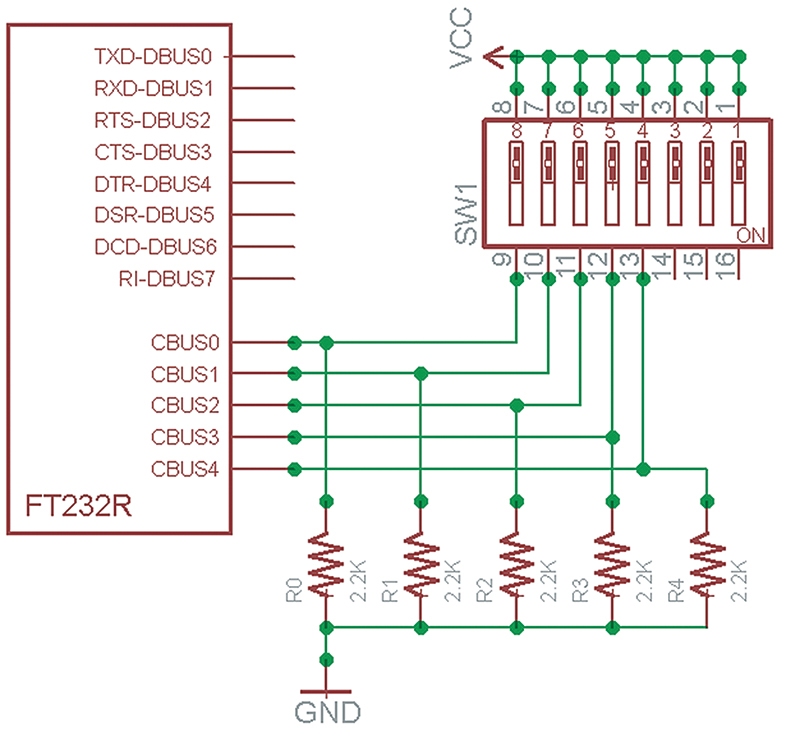
FIGURE 13. Schematic CBUS to DIP switch.
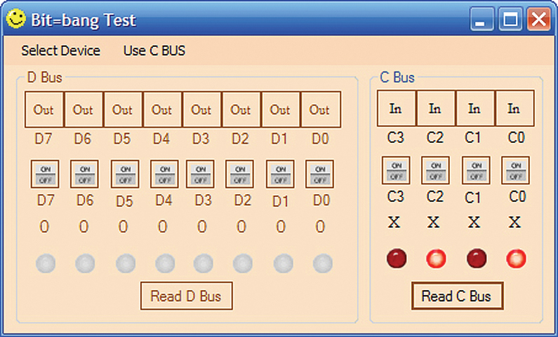
FIGURE 14. Bit-bang test read C Bus.
Instead of showing this for all three FT232R PCBs, we’ll just show the BBUSB.
Well, all that was cool, but how about we use all this for something really useful — like a USB based very small scrolling message sign? Okay, coming right up!
Bit-Banging — Seven-Segment LED
You can get the seven-segment test application shown in Figure 16 from the downloads. This program will allow us to set or clear each segment, select a character to show from a font matrix, show the whole font one character at a time, and output the classic ‘HELLO WORLD’ at the press of a button.
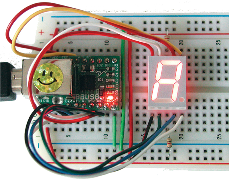
FIGURE 15. World’s smallest moving message sign?
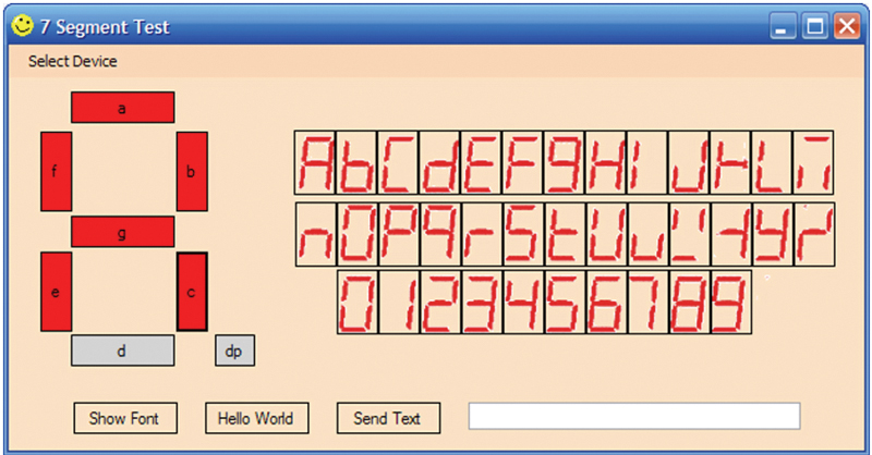
FIGURE 16. Seven-segment test application.
We have a feature that allows us to enter a string of up to 64 characters and have them scroll on the seven-seg LED by flashing each character in sequence. Some folks think you need to show at least six characters or so at one time and to show a longer message, you need to scroll the characters. While that is certainly easier to read, using one seven-seg LED will get the message across if the reader pays attention.

FIGURE 17. Seven-segment LED pin-out.
Note that although this is a seven-segment LED, it actually has eight segments when you include the decimal point, so one byte can be used to code each segment on or off.
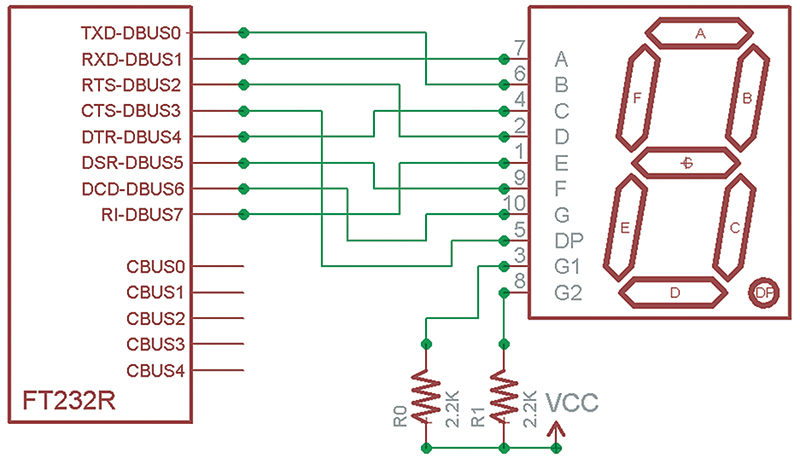
FIGURE 18. Schematic DBUS to seven-segment LED.
| DBUS |
Seven-seg pin |
| 0 |
6 |
| 1 |
7 |
| 2 |
2 |
| 3 |
5 |
| 4 |
4 |
| 5 |
9 |
| 6 |
10 |
| 7 |
1 |
TABLE 1. DBUS to seven-segment LED pin connections.
The wiring diagram in Figure 18 looks much like the one for output to the eight LEDs in the earlier section — and it is — with the main exception that the LEDs have two common resistors between pin 3 and +5 and pin 8 and +5 (Figure 17).
Build An Arduino On A Breadboard
Now for a bonus project not included in the Virtual Serial Port Cookbook book. You’ve heard about the Arduino (unless you’ve been stuck on the dark side of the moon for the past several years). I’ve written about it. Heck, everybody has written about it. What you may not know is that the original Arduino used the FT232R chip we’ve been discussing in these last two articles and since we are learning to use this device on a breadboard, why not just build us an Arduino while we are at it? The official Arduino board is about as low-cost a development board as you could ask for, so the only reason I can imagine that anyone would want to build one on a breadboard out of discrete components is that either they are a bit masochistic [and if you’ve gotten this far in this article, you may well be] or they really want to have all the pieces available for some serious electronic prototyping.
We discussed another version of the BreadboArduino back in the April ‘10 Nuts & Volts, but in that one we used the SparkFun board. Let’s supplement that by rebuilding it with the Gravitech board as shown in Figure 19 (based on the BreadboArduino schematic shown in Figure 20). There is one slight problem with getting the parts on your own though. The ATmega328 must have an Arduino compatible bootloader for it to work with the Arduino IDE.
You can purchase raw ATmega328s and load the bootloader yourself, but that requires programmers that are usually more expensive than a pre-built Arduino. You can even convert a regular Arduino so that you can use it to program the bootloader onto a raw ATmega328, but that’s all kind of a hassle isn’t it? So you can get an ATmega328 with a bootloader on it in the BreadboArduino Parts Kit (as listed in Table 2) from www.nutsvolts.com.
FIGURE 19. BreadboArduino on a breadboard.
Building The Breadboarduino
We will simplify our lives by leaving off the Arduino power supply section and using only the power from the USB port. Theoretically, we can take 500 mA from the USB, but there are caveats that cause me to advise using less than 100 mA. This should be enough to do a Cylon Eyes type project, but probably not enough to run motors.
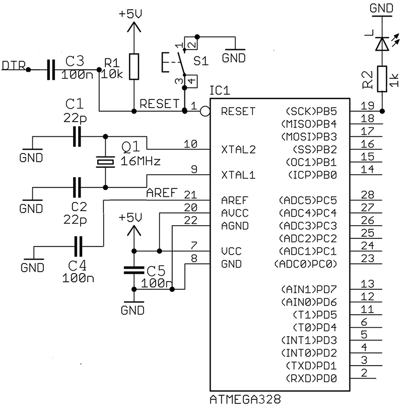
FIGURE 20. BreadboArduino schematic.
| Sch. Part |
Description |
| IC1 |
ATmega328 with bootloader |
| Q1 |
Crystal 16 MHz |
| S1 |
Mini Pushbutton |
| CI, C2 |
22 pF Capacitor |
| C3, C4, C5 |
100 nF Capacitor |
| R1 |
10K ohm Resistor |
| R2, R3, R4 |
1K ohm Resistor |
| L |
Red LED |
| |
FT232R Breakout Board |
| |
Break Away Male Headers |
| |
Breadboard |
| |
Hook-up Wire (22 AWG) |
TABLE 2. BreadboArduino Bill of Materials.
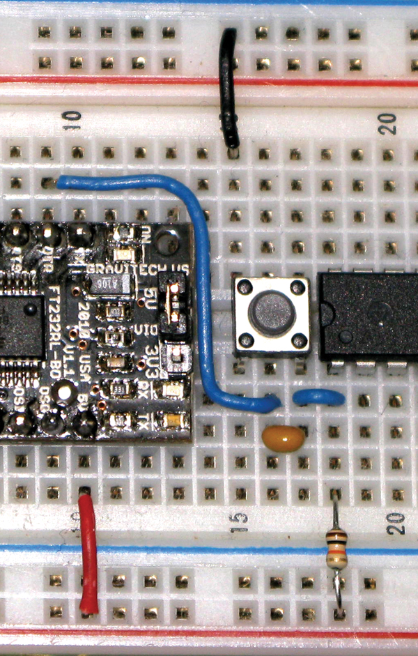
FIGURE 21. Automatic and manual reset.
When I built the section shown in Figure 21, I had the upper black wire two spaces to the right and nothing worked. Duh, running /RESET to ground tends to create that symptom — it keeps the AVR in reset so nothing happens. I moved it to the position shown and everything worked.
NOTE: The switch has short legs and doesn’t like to stay on the breadboard, so make sure that it is pushed all the way in and check it after transport. You could fix this by soldering on short pieces of wire.
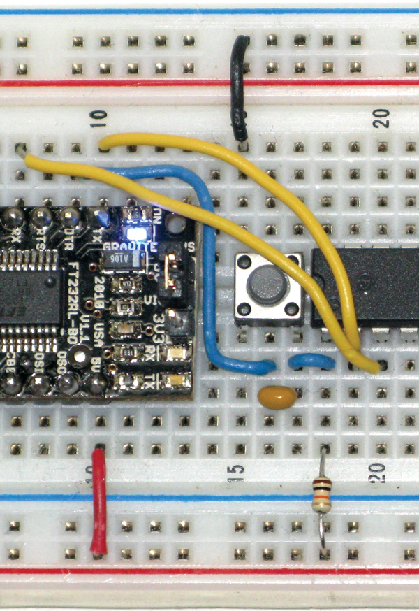
FIGURE 22. TxD and RxD.
In Figure 22, the serial communication wires are in yellow. You may need to put the paper tent label (from our last Workshop) on the FT232R breakout board to see where the TxD, RxD, and DTR go. REMEMBER: The TxD on the FT232R board goes to the RxD on the ATmega (pin 2), while the RxD on the FT232R goes to the TxD on the ATmega (pin 3). This confuses a lot of folks, but think about it for a moment. The data being transmitted from the PC through to the FT232R is being received by the ATmega, while the data being received by the PC through the FT232R is being transmitted by the ATmega. Figure 23 provides an enlargement of the section containing the crystal and the power — wire this carefully.

FIGURE 23. Crystal and power.
In Figure 19, you can see an LED on the right of the breadboard. This is connected the same as the built-in Arduino pin 13 LED, so you can test your board by uploading the Blink program from the Examples menu item in the Arduino IDE.
Hand-building systems like this on a breadboard involve very important electronics prototyping skills you’ll want to develop — BUT IT AIN’T EASY. No indeed. There are many things that can go wrong between good intentions and a working board so be patient and follow the instructions slavishly. If you have a question, start a thread on www.avrfreaks.net with BreadboArduino in the title and somebody (maybe even me) will probably have the answer. [And as usual — the warning — before posting your question to lessen the chance of getting flamed (unless you’ve got asbestos britches) read: How To Ask Questions The Smart Way: http://www.catb.org/~esr/faqs/smart-questions.html]
Well, that’s all for this two-part series. Remember that the book Virtual Serial Port Cookbook and the associated project kits to go along with these two articles are available from www.nutsvolts.com.
Next time, we'll get back to avrtoolbox and that promised porting of the Arduino serial functions to ‘real’ C. NV
The Virtual Serial Port Cookbook Revision and the kits to go with this series of articles can be purchased online from the Nuts & Volts Webstore at www.nutsvolts.com or call our order desk at 800-783-4624.
Downloads
Smiley’s Workshop 34 Download