Recap
Last time, we went a little deeper into pointers and started on the Chaser Light Marquee Frame project. Let's continue even even deeper into pointers and finish up the hardware project. Note that this episode's theory and lab sections are only loosely related, much like broccoli and coconut pie. Eat your healthy theory first, then you can have your tasty lab for dessert.
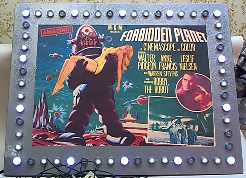
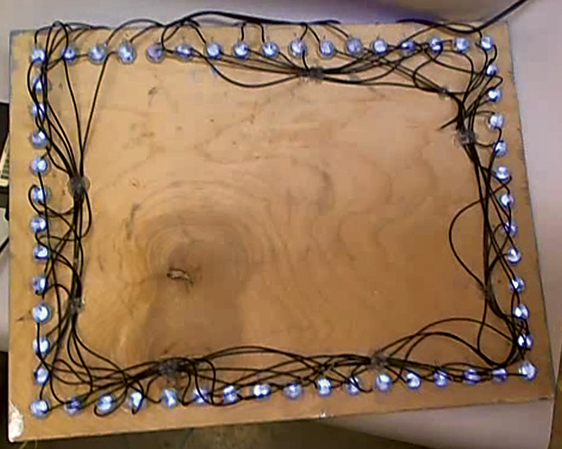
FIGURE 1. DIY chaser light marquee.
Theory
I strongly suggest that you read the Simple Chaser Light Kit sections of Workshops 44 and 45 before continuing. By the way, I keep repeating this but there will be a lot of repetition in this discussion of pointers since I think it is a difficult concept. If you’ve got a concept, then just skim the repetition and bear with those of us who are using duller pencils.
What are Pointers in Hardware?
A pointer is the address of some data.
Store ‘S’ (0x53)(1010011) at address 12708 (0x31A4) (11000110100100)
Even though pointers were difficult for me to grasp, I think that they may be even more difficult for contemporary novices who did not get the experience of programming computers with switches like we dinosaurs got. Let’s look at the seemingly simple task of loading the string ‘Smiley Micros.’ We’ll load the first character ‘S’ into memory at address 12708 on a switch programmed computer. Figure 2 shows the toggle switches on the SWITCH REGISTER set to 00000000001010011 which is the ASCII code for S in binary.
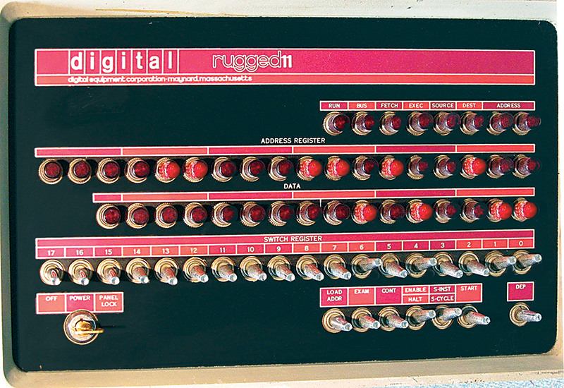
FIGURE 2. PDP11 front panel.
You can see that the SWITCH REGISTER corresponds to the data line of lights, with the up switch toggles showing a red light and the down toggles showing no red light. In the prior operation using the toggle switches, we set the ADDRESS REGISTER to the address 12708 that is binary 000011000110100100. You can see in the figure that there are two registers associated with the data value for S: one is the data itself and the other is the address of that data. In order to input some simple text into this machine, we would be standing in front with a clipboard that has the text to input: ‘Smiley Micros’ in binary so that we can enter it on those PDP11 switches. As you can see from Table 1, you’ve got 13 binary numbers, each with eight bits meaning that you have to correctly set 104 switch positions just for the text.
| Table 1. Smiley Micros in hex and binary. |
| CHAR |
HEX |
BINARY |
| S |
0x53 |
01010011 |
| m |
0x6D |
01101101 |
| i |
0x69 |
01101001 |
| l |
0x6C |
01101100 |
| e |
0x65 |
01100101 |
| y |
0x79 |
01111001 |
| space |
0x20 |
00100000 |
| M |
0x4D |
01001101 |
| i |
0x69 |
01101001 |
| c |
0x63 |
01100011 |
| r |
0x72 |
01110010 |
| o |
0x6F |
01101111 |
| s |
0x73 |
01110011 |
I also have to set the sequential address of each byte in memory — a bunch more switch toggles. That is a lot of work and it is very error prone, all just to load the text Smiley Micros into memory. It is truly a wonder that anyone ever got these things to work.
Now, my purpose here is not to bore you with elder programming war stories [I had to walk five miles through the snow to program computers when I was a kid — and it was uphill both ways!]. I just want to help you to become clearly aware that the data and the address of that data are separate entities. Each is a form of data that has to be stored somewhere in the computer. As we showed earlier, in C the data is kept in variables with a data type of char, used as:
// declare a char variable and set it to ‘S’<br />
char myVariable = ‘S’;
C converts characters delimited with single quotes to the hexadecimal value of that character:
char myVariable = 0x53; // same as ‘S’
The program text ‘myVariable’ is internally an alias for the address of the variable and the 0x53 is the data stored at that address. Make sure you understand this. The variable name is an alias for our convenience so that C understands it to be the address for the variable. So, instead of having to remember that my variable, myVariable, is stored at address decimal 12708 (or worse, binary 11000110100100), we can tell C that when it sees the word myVariable it knows that I mean the address 12708. When I assign a value to myVariable as I did with myVariable = ‘S’, C knows to store the ASCII value (0x53) of S at the memory location 12708. Got it so far?
Next, we will see how to use that address as a variable. Don’t get confused here. The data at an address is a variable, but the address of that data can also be considered a variable. In our case, the data variable is one byte and the address variable is two bytes. Considering an address as a variable can come in very handy, as you’ll see later when handling large blocks of continuous data.
A pointer is a variable that can hold an address of another variable. We can define a pointer for a character as follows:
// declare a variable that will contain the<br />
// address of a char<br />
char *myPointer;
The ‘*’ operator instructs C that this is a pointer to a character. If we want to get this to point to the character we defined above, we write:
// set myPointer to the address of myVariable<br />
myPointer = &myVariable;
If we want to use myPointer to reference the data in the variable myVariable, we dereference the pointer as follows:
// define anotherVariable to hold the data ‘A’<br />
char anotherVariable = ‘A’;
// load anotherVariable with the char pointed to<br />
// by myPointer<br />
anotherVariable = *myPointer;
Now, anotherVariable hold the data ‘S.’ Let’s run this in Pelles C (discussed last episode) just to make sure:
// Comments removed for brevity<br />
#include <stdio.h>
int main()<br />
{<br />
  char myVariable = ‘S’;<br />
  char anotherVariable = ‘A’;
char *myPointer;
  printf(“Begin with myVariable =<br />
  %c\n”,myVariable);<br />
  printf(“and anotherVariable =<br />
  %c\n\n”,anotherVariable);
myPointer = &myVariable;
anotherVariable = *myPointer;
  printf(“End with myVariable =<br />
  %c\n”,myVariable);<br />
  printf(“and anotherVariable =<br />
  %c\n\n”,anotherVariable);<br />
}
The results are shown in Figure 3.
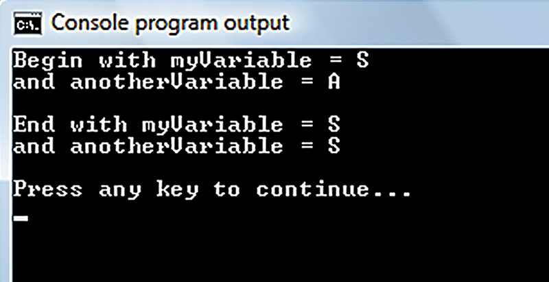
FIGURE 3. First pointers demo.
Pointers With AVRStudio
We can write another simple program for the AVR to also illustrate this:
#include <stdio.h><br />
#include “c:\avrtoolbox\libavr\source\driver<br />
\usart\usart.h”
int main()<br />
{<br />
  // Initialize usart for printf<br />
  usart0_init_baud(57600);
  // Declare a char variable and set it to ‘S’<br />
  char myVariable = ‘S’;<br />
  // Declare a pointer to char by using *<br />
  char *myPointer;
  // Get the address of the char variable<br />
  // Note that there is no * on the pointer name<br />
  myPointer = &myVariable;
// Use the pointer to get contents of
‘myVariable’<br />
  // Note that this does require the *<br />
  printf(“myPointer points to:<br />
  %c\n”,*myPointer);
}<br />
The output is: myPointer points to: S
One More Time
Understand that a pointer is the address of a location in memory. Ordinary variables are data, while pointers are variables that contain the address of other variables. The data you want is in memory and the address of that data is a pointer to that data. Note that the data that a pointer points to can also be a pointer. You define a pointer variable with * and you extract the address of an ordinary variable with '&.' Note that you do not use the * on the pointer when you get the address of the variable using the &:
  char myVariable = 'S';<br />
  char *myPointer;
myPointer = &myVariable;
  printf("myPointer points to:<br />
  %c\n",*myPointer);
We saw Figure 4 last time.
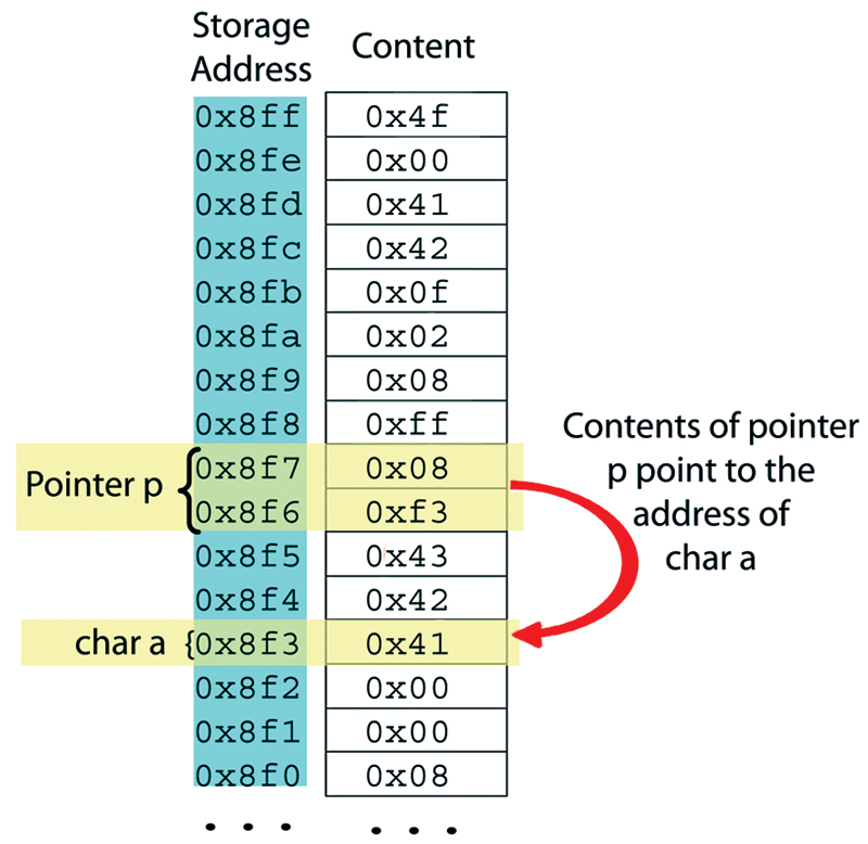
FIGURE 4. Pointers in AVR memory.
It shows a block of ATmega328 SRAM memory where we see the highest 16 memory locations, and we note that the pointer p — which is two bytes long — is located at addresses 0x8f6 and 0x8f7. It has been set to point to the char a located at 0x8f3. You will also see that the data in 0x8f6/7 is the address of the char a. Next time, we will see that the * operator tells C to use the address stored at the pointer location to get the data at that pointed-to address, which is 0x11. Well, this is all very illustrative, but how did we get the data for this illustration in Figure 4? It comes from the following:
#include <stdio.h><br />
#include "c:\avrtoolbox\libavr\source\driver\<br />
usart\usart.h"
void printMyBlock(char *p,int mB);
int main()<br />
{<br />
  // Initialize usart for printf<br />
  usart0_init_baud(57600);<br />
 <br />
  char a = 'A';<br />
  char b = 'B';<br />
  char c = 'C';<br />
  char *p;<br />
  char *q;
  // Point to top of SRAM<br />
  q = (char *)0x8ff;<br />
  // Point to the char a;<br />
  p = &a;
  printf("Pointer p address: &p = %p\n",&p);<br />
  printf("Points to content *p = %c\n",*p);
  printf("\nContent of top 16 memory<br />
  locations:\n");<br />
  printf("Address   Content\n");
  printMyBlock(q,16);<br />
}
void printMyBlock(char *p,int mB)<br />
{<br />
  for(int i = 0 ; i < mB ; i++)<br />
  {<br />
    printf(" %p       0xx\n",p-i,*(p-i));<br />
  }<br />
}
You should pay careful attention to how we use pointers to access sequential locations in memory using *(p-1), where i is incremented in the for loop. Since *p points to the top of the ATmega328 SRAM at 0x80ff, then subtracting 1 from it points it to the next lower address 0x80fe; continuing to subtract 1 sequences the address further down until we have 0x80f0. Also note that we passed the pointer by using just the pointer name without the *. These are tricky factoids that you must master to consider yourself proficient in C.
You can find the source code for this in avrtoolbox\avr_applications\pointer_test\. When you compile this code, you will get a warning that variables b and c aren't used. They are included just to pack two spots in memory, as you'll see in a moment. When you run this code, you get the output on Bray's terminal shown in Figure 5, which just happens to be the data shown in Figure 4.
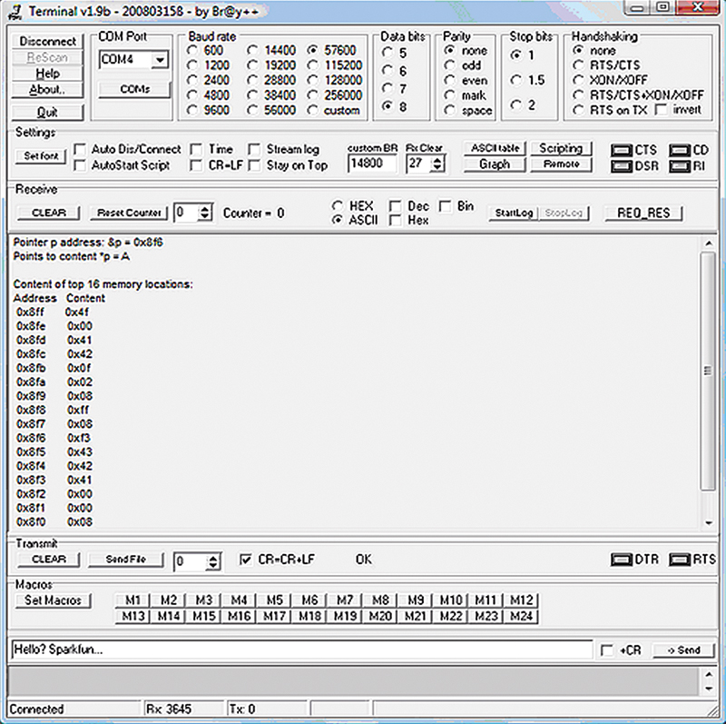
FIGURE 5. Output from pointer_test on Bray's Terminal.
Well, I've explained pointers as best I can, redundantly over-explaining them from several angles. If you haven't got it by this point, try writing your own code and asking questions (careful well-formed questions) on www.avrfreaks.net. Someone there might be able to help.
Lab
Last episode, we started with a picture of a Photoshopped mockup of a movie lobby card chaser light frame and we discussed the theory for using the simple chaser lights kit to drive 56 LEDs from eight bits of output. We also saw the schematics and bill of materials. Now, we'll discuss how I built a hardware prototype as shown in Figure 1, and demonstrate it in the YouTube video titled 'LED Chaser Light Frame' at www.youtube.com/watch?v=0wLZwqjYSDk.
Measure Twice, Cut Once
Or, maybe measure 12 times and cut once? Spacing 56 LEDs around a lobby card is harder than it looks. I had an image of a lobby card for the movie ‘Forbidden Planet’ and decided that I would array 56 LEDs (which are seven sets of the eight LEDs available for the simple chaser lights output.) Naturally, I wanted to keep this as simple as possible, but I discovered very quickly that spacing those LEDs at some easily measurable intervals around a picture size (that I initially set as 11 x 14 inches which is a standard frame size) was a nightmare of fractional inches that I just didn't have on my ruler. I really wasted a lot of time on this trying to get it to some actual measure that could be expressed on 1/8 inch intervals (or even 1/16), but it never looked right. So, finally I settled on making the LED intervals at one inch each and then simply fit the lobby card image using Photoshop to get it close to the inner frame dimensions (I ended up chopping the 11 x 14 to 10 x 14).
Figure 6 shows that I used a T-square and a ruler to draw the inner and outer frame dimensions, along with the LED positions on some newsprint. Even though I was confident in my math, I nonetheless had to re-do this three times to get the final dimensions that I found acceptable. Maybe you'll find this process easier than I did.
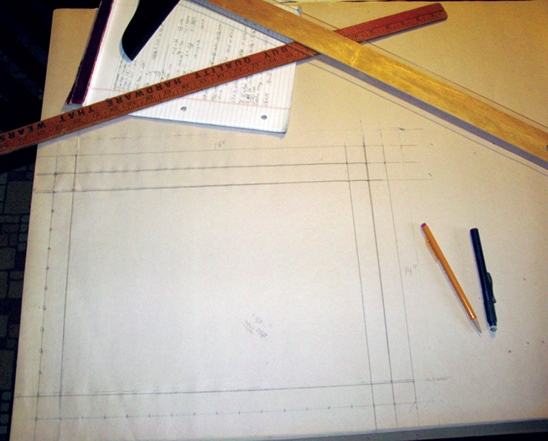
FIGURE 6. Drawing for frame dimensions.
By this point, I was so nervous about getting this right that I decided to do my prototype using a piece of inexpensive 1/4 inch plywood (smooth beech on one side), cut to 18 x 14 (Figure 7). I then carefully transferred the drawing to the board.
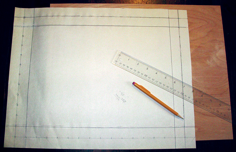
FIGURE 7. Drawing for frame on plywood.
Dimensions
Frame outside: 18 x 14 inches.
Frame LEDs: 16 x 12 inches with LEDs spaced one inch apart.
Frame inside (image size): 10 x 14 inches.
Figure 8 shows the paper dimensions transferred to the plywood.
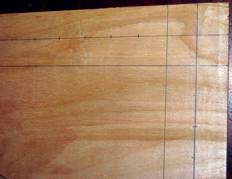
FIGURE 8. Frame dimensions transferred to plywood.
I used a drill press and was very careful to get the drill centered before drilling. Figure 9 shows the drill — 1/2 drill since the LED bezels are ~1/2 inch. (More on this "~1/2" in a moment).
FIGURE 9. LED holes drilled in plywood.
I recommend trying this with a few holes on some scrap board so you can learn how to lessen the ripping up of chunks which seems very easy if you move the drill too fast.
I also bought some hammered metal-silver spray paint so that the prototype would look a little more like the metal frame (Figure 10) I envisioned that rather than a ratty piece of plywood. Yes, I'm an optimist.
FIGURE 10. Frame spray painted.
Figure 11 shows the bezels and the LEDs from the back.
FIGURE 11. Mounting bezels and LEDs.
The "~" 1/2 inch for the bezel drill is from the fact that the bezels were in metric dimensions and I could only find an English drill. The 1/2 inch was close but wasn't quite right, so I compensated by using the ancient technique of shoving them into the hole with pounding, cursing, and sweat. [Of course, it turned out looking like a ratty piece of plywood painted with hammered metal-silver, but what are prototypes for? It did confirm to me that the dimensions were sound and the LED appearance was more or less what I expected.] Next, I wired it up according to the schematic shown in Figure 12.
FIGURE 12. Schematic for LED matrix and ULN2803 driver.
Last episode, I mentioned that I scrounged an old printer power supply that said 30 volts on the case. Since the LEDs dropped 3.4 volts each, I assumed that 3.4*7 = 23.8 volt drop. However, when I started running things, I noticed that the power supply was actually putting out 38 volts, until I hooked it all up and ran it. Then it seemed to be supplying 28 volts. Either way, the LEDs were too bright so I ended up using 2 Kohm resistors which gave an acceptable brightness at whatever the real current was. Nothing heated up, caught fire, or exploded, so I'm happy.
You may notice that this schematic differs from the one shown last time where I indicated using discrete transistors. That would work, but I just happened to have a ULN2803 lying around and thought it would be easier to wire up on the breadboard as shown in Figure 14. [Note also that the L0 to L7 in Figure 12 refer to the LED0 to LED7 signals shown in Figure 9 from our last article.]
Figure 13 shows the mess that occurred while building.
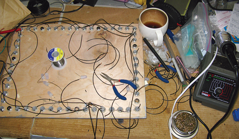
FIGURE 13. Wiring it up.
Note that the deep stains in the cup are from tea — lots and lots and lots of tea — that I drank while building this device. This was due to burning out a string of seven LEDs, then immediately burning out another seven right before a long grumpy walk in which I barked back at several annoying dogs who failed to realize how easy they have it compared to that of the lonely fumble-thumbed prototyper.
Notice in Figure 14 that I put masking tape flags on each wire marking the LED line number and whether it went to P for power or G for ground.
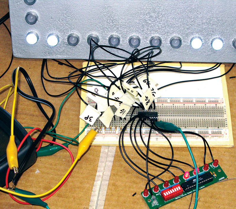
FIGURE 14. Breadboard close-up.
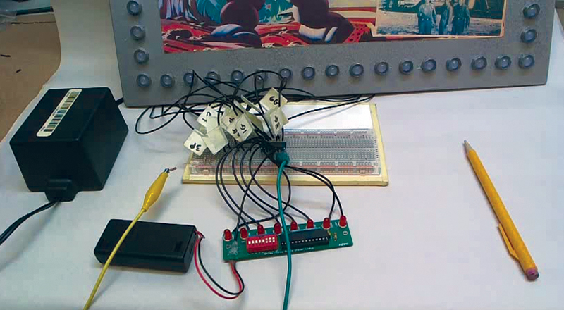
See It in Action
After the hours of building, the burned-out LEDs, and the impolite dogs, I fired it up and started running the various patterns that come with the Simple_Chaser_Lights kit. To my surprise, many of those patterns are boring on a frame.
The show_all function in the code supplied with the kit is sort of okay, but some of the patterns just don't translate well. So, I decided to write another program that would show a few select patterns in a way that would be a bit more attractive.
Chaser Demo 1.
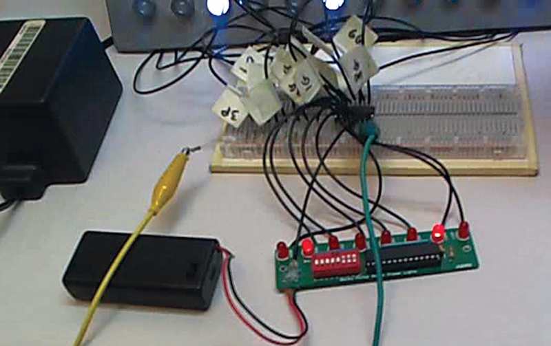
Chaser Demo 3.
Chaser Demo 4.
Chaser Demo 5.
Remember, though, that the kit does not have a bootloader or serial communications, so you'll have to have a device that can program an ATmega328 such as the STK-500 or an AVR Dragon. I made a video (titled 'LED Chaser Light Frame') of it running some patterns that you can see on YouTube at www.youtube.com/watch?v=0wLZwqjYSDk. I shot the video with the frame on the desk where I made it rather than cleaning it all up and hanging it on the wall like you might expect. I was afraid that if I moved it ... well, who knows what might happen. It's a breadboarded prototype, after all.
Since the source code for the frame is different from that for the simple chaser lights kit, I've bundled it into a zip file (simple_chaser_frame.zip) that you can get from Nuts & Volts. See you next time! NV
Theory is all well and good, but to really learn this stuff you have to get your hands on some tangible items that blink, whirr, and sometimes detonate. As a service for the readers of the Smiley’s Workshop articles, we have simple and inexpensive projects kits available that can help you make it real. You can find these kits (and some darn good books) at the Nuts & Volts Webstore.
Nuts & Volts now carries the entire line of Smiley Micros books and kits. Some are shown in the magazine and others in their web shop. If you just can't wait and want to get a leg up on real C programming for the AVR (while helping support your favorite magazine and technical writer), then buy my C Programming book and Butterfly projects kit, or if you are a complete novice try The Arduino Workshop and projects kit.