Previously, we learned what makes an oscillator do what it does, and tried a simple low frequency example. Now, it's time to move up — in frequency — to the oscillators which make the signals that drive the ham's wireless world.
Let’s review for a moment. First, oscillators need gain (A), a frequency-selective filter, and a positive feedback loop (ß) that all combine to satisfy the Barkhausen criterion, Aß = 1.1 Even if you didn’t intend to create an oscillator, if those three conditions are present, an oscillator you will have!
At RF, the two fundamental oscillator types were devised to create feedback through reactances that formed a voltage divider with inductance (the Hartley oscillator) or capacitance (the Colpitts oscillator). That’s where we left things.
Practical RF Oscillators
The two schematic snippets in Part 1 showed the basic idea but weren’t practical circuits, omitting such important items as power supplies, biasing, and output connections. So, how do we make an oscillator, really? Figures 1 and 2 show a pair of actual functioning oscillator circuits.
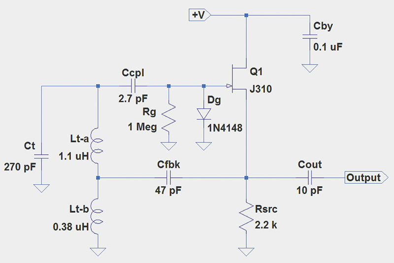
FIGURE 1. The Hartley oscillator will operate around 7.9 MHz. J310 JFETs in through-hole TO-92 packages are available from Mouser Electronics (www.mouser.com) and in SMT packages from many suppliers. Inductor Lt-a consists of 17 turns of #24 or #26 solid wire on a 0.5” diameter, type 6 powdered-iron toroid. Inductor Lt-b is 10 turns on a 0.3” diameter, type 6 powdered-iron toroid. For best stability, Ct should be a polystyrene film or silvered-mica capacitor. Powdered-iron types refer to Amidon Corporation products (www.amidoncorp.com). +V can be from 6V to 15V with excellent results.
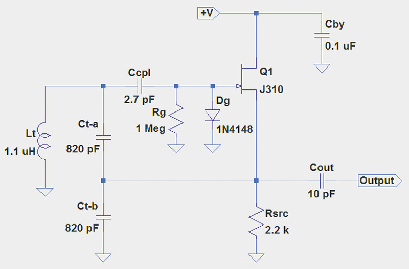
FIGURE 2. The Colpitts oscillator will operate around 7.5 MHz. Inductor Lt is the same as Lt-a in Figure 1, and both Ct-a and Ct-b should be polystyrene film or silvered-mica capacitors.
You can build them and listen to their output signal on a world band or ham receiver between 7.5 and 8 MHz. (You’ll need to listen in SSB or CW mode since the steady output has no modulation for an AM radio to detect.)
Each of the oscillators has a parallel-LC “tank” circuit that is a filter at its resonant frequency. The filter, in turn, determines the oscillator’s frequency. Those components have the designators Ct and Lt.
Why is an LC circuit called a tank circuit? Because it stores energy like an electrical flywheel. The energy sloshes back and forth from the inductor to the capacitor at the circuit’s resonant frequency. The positive feedback supplies a little energy and the JFET’s gate takes a little out. The resonant frequency of the tank circuit is:y
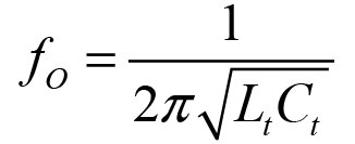
For the Hartley circuit (Figure 1), Lt = Lt-a + Lt-b = 1.48 µH because the two inductors are in series, thus ƒO = 7.96 MHz. In the Colpitts circuit (Figure 2), Ct = (Ct-a x Ct-b) / (Ct-a + Ct-b) = 410 pF because the two capacitors are in series. Thus, ƒO = 7.5 MHz. Both circuits are from an excellent electronics design reference, Experimental Methods in RF Design by Hayward (W7ZOI), Campbell (KK7B), and Larkin (W7PUA).
What is the purpose of the other circuit components? Cbyp is a bypass capacitor to keep the drain of the JFET at signal ground. This is a common drain amplifier, similar to an emitter-follower in the bipolar transistor world. Rsrc limits current through the JFET to a few mA — depending on the value of +V — which can be from six to 15 volts with good results.
The output signal from the circuit is taken through the 2 kΩ of reactance through Cout. If more signal is desired, a high input impedance buffer amplifier (emitter- or source-follower) can be used to beef up the signal.
Rg stabilizes the DC voltage on the gate during oscillation, so that the JFET amplifies consistently.
Ccpl is a coupling capacitor that lets a small amount of RF leak out to the gate of the JFET, Q1. It has a high reactance at 8 MHz (XC = 1/2πƒC = 7.4 kΩ), so the tank circuit is “lightly loaded” — meaning that the amount of energy that gets out of the tank through Ccpl is small compared to the energy stored in the tank circuit. This helps keep the oscillator frequency stable and reduces noise in the output signal.
Cfbk in the Hartley circuit is the path for feedback from the JFET’s source to the tank circuit. Because it is supplying energy to instead of extracting energy from the tank circuit, its reactance can be lower (about 425 Ω). The lower value also adds less phase shift in this important signal path.
The source and gate signals for the gain-supplying JFET are in-phase, so feeding a signal back through Cfbk creates the positive feedback needed by the oscillator. Cfbk is required in the Hartley circuit to provide an RF signal path without allowing the DC current to flow through Lt-b to ground. It is not required in the Colpitts circuit because Ct-a and Ct-b block any DC current flow.
Dg is a funny looking component with a purpose that is not obvious. Remember that an oscillator “starts up” by amplifying noise more and more until a self-sustaining signal is present. How does the oscillator know when to stop increasing the signal level? Well, it doesn’t!
If no limiting mechanism is present, the signal will build up until it can’t be amplified any further, creating a distorted square-wave-like output. Not good for radio use!
The brute force solution is Dg which begins to conduct as the positive half-cycle of the sine wave signal becomes greater than about 0.5V. That loads down the input and reduces gain, acting as a brake on the system. (Negative peaks are self-limiting since they cut off the JFET.)
You can make the oscillators in Figures 1 and 2 adjustable — what hams refer to as a VFO which is an abbreviation for Variable Frequency Oscillator — by adding variable capacitors across the tank circuit.
A small variable capacitor of 20-30 pF across the tank circuit (from Ccpl to ground in either circuit) will shift the oscillator’s frequency by up to 10%. Changing an inductor’s value is not so easy, and clever circuit designers discovered that a variable capacitor in series with the inductor could act to cancel some of the inductive reactance, changing the oscillator’s frequency as well. This is called — strangely enough — series tuning.
Effect of Component Q
Both the capacitors and inductors that determine ƒO dissipate some of the RF energy flowing through them as heat. Loss in the capacitor is primarily caused by the dielectric material (such as polystyrene or mica), while the inductor loses energy to resistance in the wire and in its magnetic core. Remember that the skin effect limits inductor current to a very thin layer at the surface of the wire, so resistance at RF will be a lot higher than the resistance you measure with a DC multimeter.
The effect of these losses reduces the component’s — and thus the tank circuit’s — Q, or Quality Factor. Q can seem mysterious, but is a measure of energy loss with Q = Energy stored during one cycle / Energy lost during one cycle. For a component, Q is the ratio of reactance to resistance.
For example, if an inductor has 500 Ω of reactance and 5 Ω of loss resistance, it’s Q = XL / R = 500 / 5 = 100 — a typical value for inductors. Capacitors have much higher values of Q; several hundred and up. Higher values of Q mean the “flywheel” keeps turning without slowing down much or changing frequency. (The Q of an LC tank circuit is limited by the Q of the lossiest component — usually the inductor.)
Remember that the tank circuit acts as the primary filter for our feedback loop. The lossier the filter, the more noise it allows to get to the JFET, which happily amplifies anything that appears at the gate. Thus, in an oscillator, tank circuit Q determines the oscillator’s spectral purity — meaning how much the primary desired sine wave is accompanied by noise and distortion of various sorts. If you want a clean signal, use the highest quality Ls and Cs you can.
The Quartz Crystal
Even the very best LC oscillators are not all that stable, and most have plenty of noise in their output signals. Certainly, they are handy circuits, but they are not suitable for precision jobs like generating clock signals for digital circuits and master oscillators for ham radio transceivers. In those applications, a different type of tank circuit is used: the quartz crystal. Quartz is a piezoelectric material in which mechanical stress creates a voltage across the material and vice versa.
Without getting into a lengthy discussion of how piezoelectricity works, imagine a thin disc of quartz with metal electrodes applied to each side as in Figure 3A.
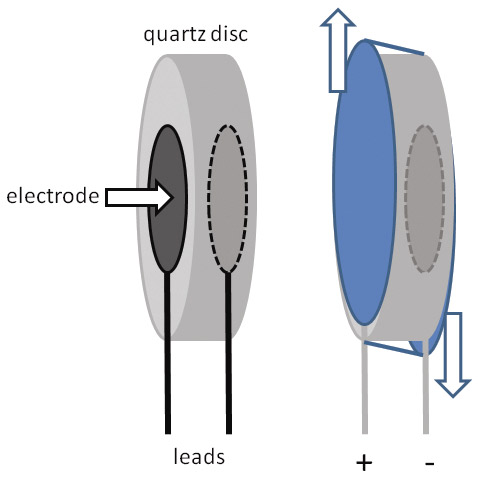
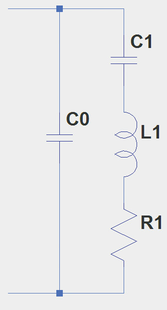
FIGURE 3. The basic construction of a quartz crystal for oscillators is shown in A, along with a depiction of the crystal’s thickness shear vibration. The equivalent electrical circuit for the crystal is shown in B and described in the text.
When a voltage is applied between the electrodes, the quartz disc deforms perpendicular to its thickness — called thickness shear — as shown in the figure. (For this type of deformation to occur, a quartz crystal must be sliced along one particular axis so that the internal molecules line up properly. This orientation of the disc is called an AT cut.)
By applying an AC voltage, standing waves can be created in the quartz disc. In return, as the standing waves move through the quartz, voltage waves are produced with the energy trading forms between mechanical and electrical. This should sound similar to how the LC tank circuit continually transfers electrical energy between the inductor and capacitor.
If the frequency of the pulses is correct, causing the disc to vibrate at its natural resonant frequency creating voltage pulses in turn, a properly configured oscillator circuit can amplify and reinforce the vibrations and voltage pulses. Just as an LC oscillator gradually builds up a steady oscillation from filtered noise, a crystal oscillator builds up the oscillation by exciting the vibrations of the quartz disc which acts as the filter.
The equivalent electrical circuit for a quartz crystal at its fundamental frequency — the lowest at which it has a natural resonance — is shown in Figure 3B. (Vibrations at higher multiples of the fundamental frequency are called overtones.) C1 and L1 represent the motion of the crystal as it vibrates. R1 represents the equivalent series resistance, or ESR of the crystal (usually a few dozen ohms), and C0 represents non-motional capacitance between the electrodes, stray capacitance in the crystal holder, and so forth.
What is special about the quartz disc is that it has extremely high Q — on the order of 100,000! (By comparison, a good LC tank circuit has a Q of only 100-200.) This means an oscillator that uses a quartz crystal to control its frequency will have excellent frequency stability and very low noise. This makes crystal oscillators the choice for demanding applications like generating reference frequency signals.
The Pierce Oscillator
The most common type of crystal oscillator is the Pierce circuit shown in Figure 4. It is a variation of the Colpitts oscillator and uses the crystal in its series resonant mode to create the positive feedback from the transistor’s collector to the base. When the crystal’s internal L and C have equal reactances, they cancel, leaving only the series resistance. There is plenty of feedback for the circuit to oscillate.
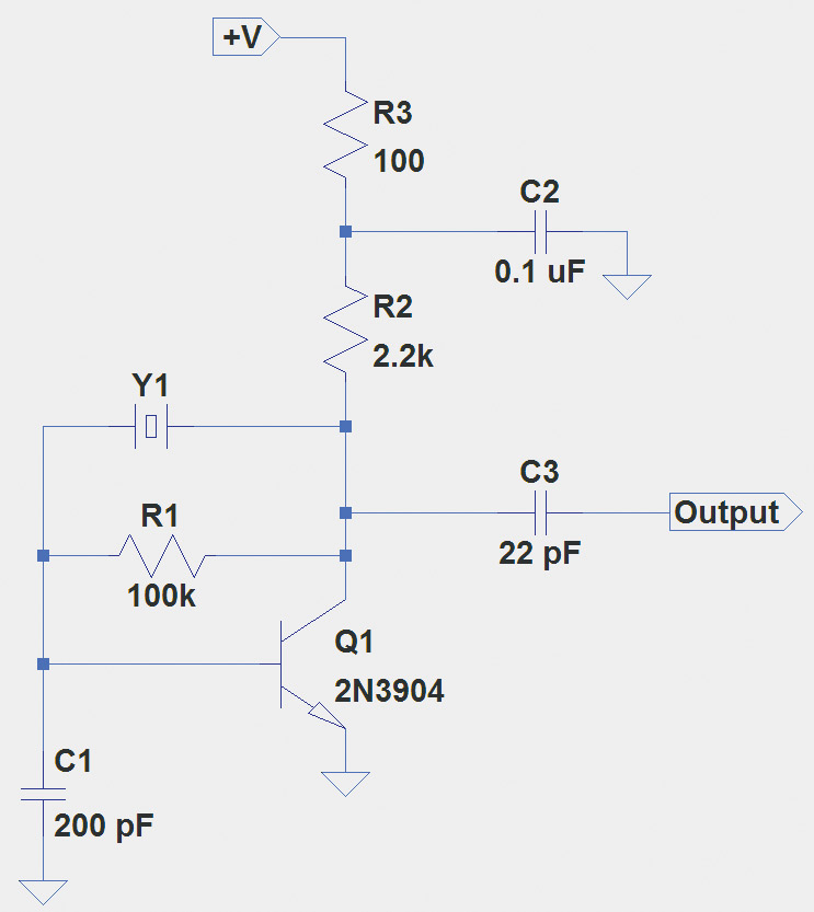
FIGURE 4. A Pierce crystal oscillator circuit that can be used from 2 to 20 MHz. If tuning of the crystal frequency is required, insert a 50 to 100 pF trimmer cap between the crystal and the transistor collector.
The sharp-eyed reader may have noticed that the feedback path is from the transistor’s collector which is 180° out of phase with the base. This is opposite of the circuits in Figures 1 and 2 where the feedback was from the JFET’s source which was in-phase with the gate.
The extra phase shift is supplied by the crystal which — at series resonance — has between 45° and 60° of phase shift through it, requiring the extra phase shift created by R1 and C1 to make the total phase shift of 360°. R1 also provides bias for the transistor’s base.
This circuit (also from Experimental Methods for RF Design) is not critical and will work with most crystals from 2 to 20 MHz. Any high speed NPN transistor will probably work fine. This gadget makes a terrific flea market crystal tester if a buffer amplifier is added at the output, with a simple signal detector using an LED for a visual indicator.
There are better designs for signal stability, lower noise, etc., but this simple oscillator will get you started. If you wish to “trim” the crystal’s frequency to an exact value, an adjustable capacitor of 50 to 100 pF in series with the crystal will do the job.
Since hams aren’t bound to fixed frequency channels most of the time, an acceptable workaround was needed to provide good frequency stability with some flexibility. Thus, the VXO or Variable Xtal (crystal) Oscillator was developed and has been used in many low power and homemade radios to simplify circuits, while still providing a good quality signal. This topic would make great extra-credit reading!
Logic Gate Oscillator
Digital designers often use a variation of the Pierce circuit with the gain provided by an inverter as in Figure 5. Rfbk biases the inverter into its linear region so that it can act as a proper amplifier. C1 and C2 create the necessary phase shift along with Rs so that there is a full 360° phase shift around the full circuit.
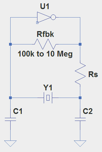
FIGURE 5. Logic inverters can be used with a crystal as shown here, providing a digital square wave output waveform directly. This type of circuit is popular with microprocessors which often provide an inverter specifically for creating a clock oscillator.
Because there are many types of logic families and these circuits are used over a wide range of frequencies, I recommend that you read the excellent tutorial on logic gate oscillators from the Crystek company — a well-known manufacturer of crystals.2 Another classic reference on logic gate oscillators is the 1974 Fairchild App Note 118 on CMOS Oscillators.3
More Oscillators, Baby!
This pair of columns has barely scratched the surface of oscillator types and designs. There are many variations as you will see when you start looking for them.
Nevertheless, you now know a little bit about the fundamentals of how oscillators work. I’ll bet you can already feel your knowledge building up to a steady oscillation! NV
Hooked on Microphonics
If you build either of the oscillators in Figures 1 or 2, tune them in on a receiver and let them stabilize thermally so the signal is not drifting much. Then, very very gently, tap on the circuit board or workbench near the circuit while listening to the signal. In all likelihood, the oscillator’s frequency will jump with every tap.
This sensitivity to mechanical vibration is called microphonics. Any type of vibration will cause an oscillator’s frequency to change. In fact, if you take the receiver into another room and have your assistant say something like, “Watson, come here, I need you!” very loudly and directly onto the oscillator, you’ll probably be able to hear the oscillator’s frequency being modulated by the voice.
You will also notice long-term slow changes in frequency — quicker if you bring a heat source near the oscillator’s tank circuits. This is called thermal drift. It’s hard to make a stable LC oscillator.
If this discussion of oscillators whets your whistle, you can find a lot of hands-on circuit building and operation among ham radio's busy and active QRP (low power) enthusiasts. Low power "rigs" (radios) are inexpensive to build and modify, and there is a lot of sharing and encouragement between "QRPers" as they design and build their gear. You can find out more about QRP operating on the ARRL's Tech Portal web page at www.arrl.org/tech-portal under "Technial Specialties." Click on QRP - Low-Power Operating to find a long list of clubs and web resources.
Resources
en.wikipedia.org/wiki/Barkhausen_stability_criterion
https://www.crystek.com/home/crystek/appnotes.aspx
www.fairchildsemi.com/evaluate/application-notes/familyDetails?id=10789