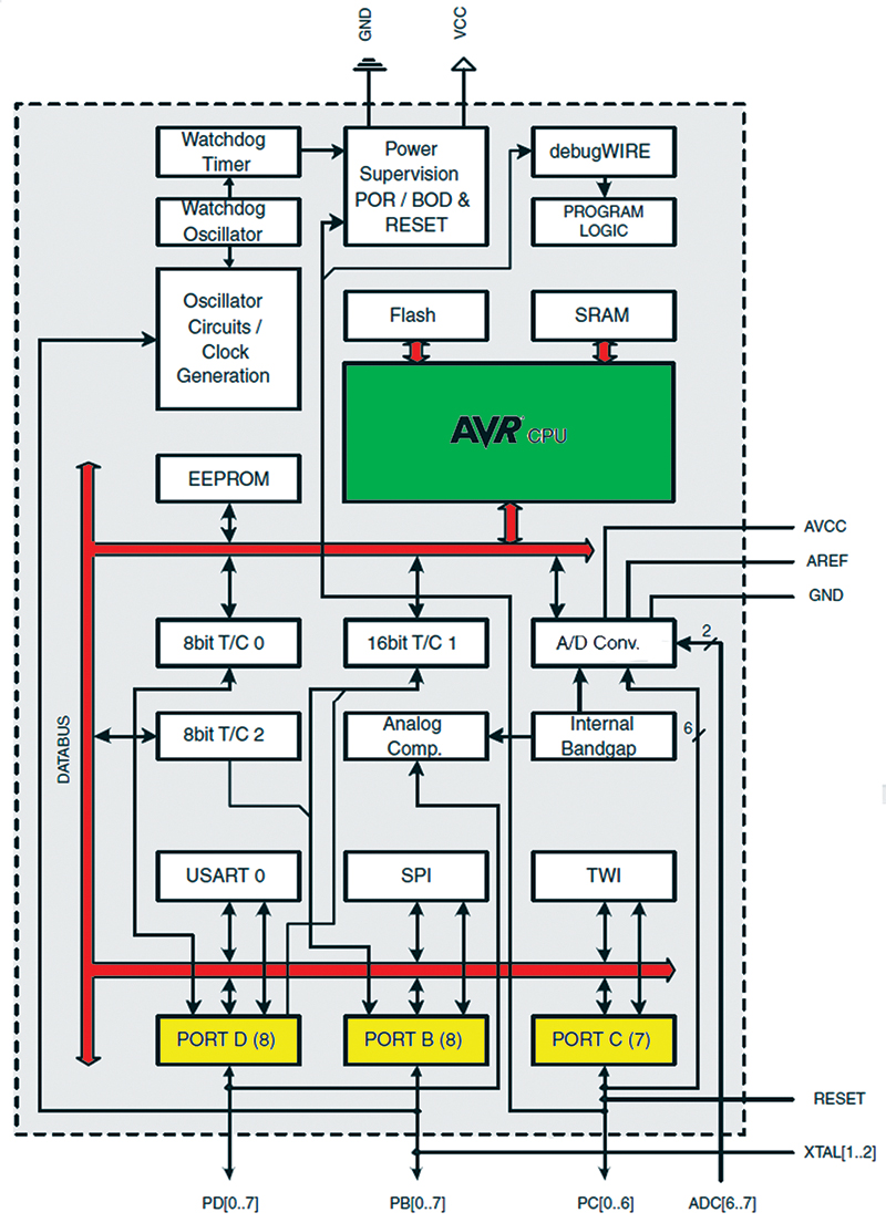
FIGURE 1. AVR hardware block diagram.
Attention Readers - SInce Google Code is shutting down, Avrtoolbox has been exported to https://github.com/nutsvolts/avrtoolbox. At this time, not all of the code files mentioned in the Smiley's Workshop series are available there. We are working on the problem and hope to have it resolved very soon.
Recap
Last episode in Part 1, we started looking at digital I/O (Input/Output). We got our toes wet with a library to provide Arduino-like elementary functions, and then jumped into the deep end looking at the I/O pin’s electrical characteristics. You might have found that my switching from relatively simple software to some fairly complex AVR hardware architecture caused a bit of technical whiplash, but I haven’t yet figured out a way to discuss both the AVR hardware architecture and the hardware independent C software without floundering around a bit. You really need to know both to use either, but the connection is kind of fuzzy. This time, we are going to jump off the high board into both hardware and software by confronting the AVR digital I/O peripheral registers and learning how to manipulate them in software.
Let’s approach this by first looking at the hardware, then move on to some additions to our elementary digitalio functions that we’ll apply to reading an eight-bit DIP switch and writing to eight LEDs using the Butterfly and the Arduino board (used with AVRStudio 4 and the avrtoolbox\libavr\elementary library instead of the Arduino IDE and library). Finally, we’ll apply all that to yet another chaser lights program.
Digital I/O is Memory Mapped
We had an extended discussion of AVR memory architecture and C programming in Smiley’s Workshops 23 through 27 (June through October 2010). We learned that the AVR has two main memory spaces — data and program — in different physical locations. One of the things we didn’t go into then is that the AVR hardware peripherals are mapped into the data memory. This means that peripherals like timers/counters, ADC, PWM, etc., are viewed by the AVR core as being memory locations to set up the functionality and read the results. Likewise for digital input and output, the AVR core sees input and output ports and pins as just bytes and bits in data memory locations to be written to or read from. We can get a better view of this in Figure 1 which shows the AVR core in green, the main data bus in red, and the digital I/O ports in yellow.
The data memory space is shown in Figure 2 and consists of the 32 lowest bytes used for general-purpose processor working registers, then the next 64 bytes used as I/O registers, followed by 160 bytes of extended I/O registers, and then finally beginning at address 0x0100 (decimal 256), the SRAM. The digital I/O is mapped into the 64-byte registers section as shown in Figure 3.
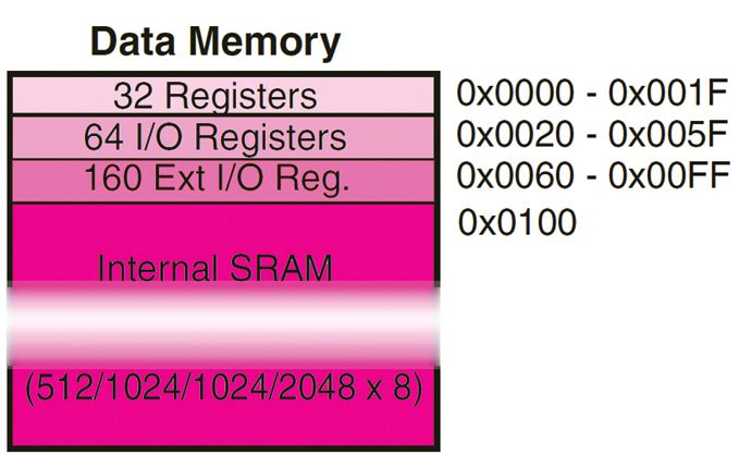
FIGURE 2. Data memory.
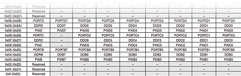
FIGURE 3. PORT, PIN, and DDR memory map.
Digital I/O is Based on Registers
These digital I/O registers are eight-bit bytes. Any bit within that byte (which to the outside world is an I/O pin) can be individually addressed without affecting any other bit/pin in the byte/port. This is an important concept since it allows us to have one port pin set as an input and another set as an output, with the ability to change either without affecting the other.
So, how does this work? Figure 4 provides some visual clues. Each port has three registers associated with it. A data direction register, DDRx, will — as the name suggests — set the direction of the port to input or output. There’s a PORTx register you use to write data to that is then output on the port pins. A very poorly named register, PINx, lets you input data from the port pins. Why do I say it is poorly named? Because it is a full eight-bit byte-sized representation of the port input and isn’t restricted to a single pin as the name may imply. They might have named these with out and in — POUTx and PINx — to be less confusing, but folks would laugh at POUT and still confuse PIN with pin. Maybe PORTOUTx and PORTINx would have been clearer (but who wants to type that much).
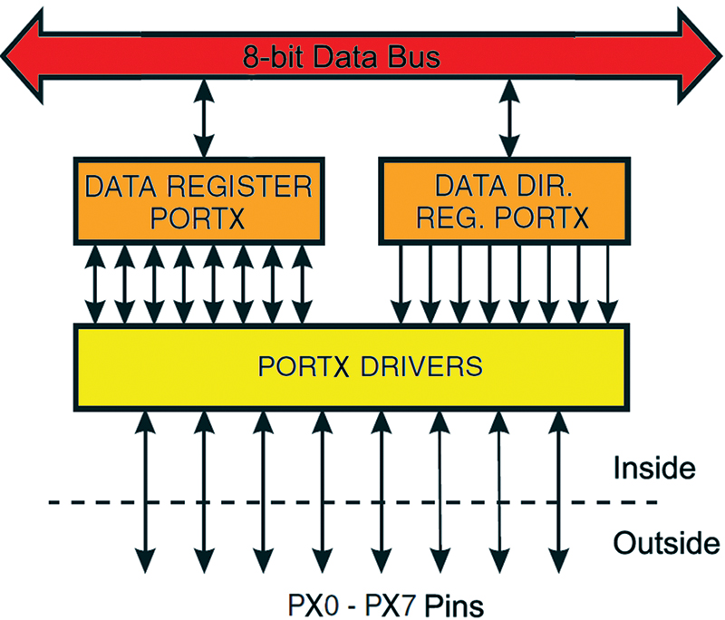
FIGURE 4. Port I/O module.
This is one of those weird things that you just have to get used to and memorize — that you write to the eight bits as PORTx and you read the eight bits as PINx. If you want to actually look at any one pin of a port, then depending on whether you are reading or writing (based on the DDRx setting for the pin), you have to use the bitwise operators to do that single pin reading and writing. Since this invariably bites novices, let me repeat: You write eight-bit output to PORTx and you read eight-bit input from PINx.
Now, memorize this: Writing a 1 to a DDRx bit sets the port pin for that bit to output. Writing a 0 to a DDRx bit sets the port pin for that bit to input. So, 1 = output; 0 = input.
Avrlibc Input Output Header Files
Among the many goodies supplied by avrlibc is a header file that allows you to use convenient #define constants for the registers and bits associated with the ports and pins. The Arduino-like simplification that we learned last time in Workshop 39 provides a layer of code that is great for doing ‘simple.’ If you want to get a little deeper with real C, then having the io.h constants helps keep things sort of simple without having to get right down to the actual register names.
When you compile a file in AVRStudio, you first select the AVR device in the projects options as shown in Figures 5 and 6 where we select the atmega328p. This selection is used by AVRStudio to generate a makefile that is used by the version of gcc supplied by WinAVR to compile and link the text into your executable .hex file.
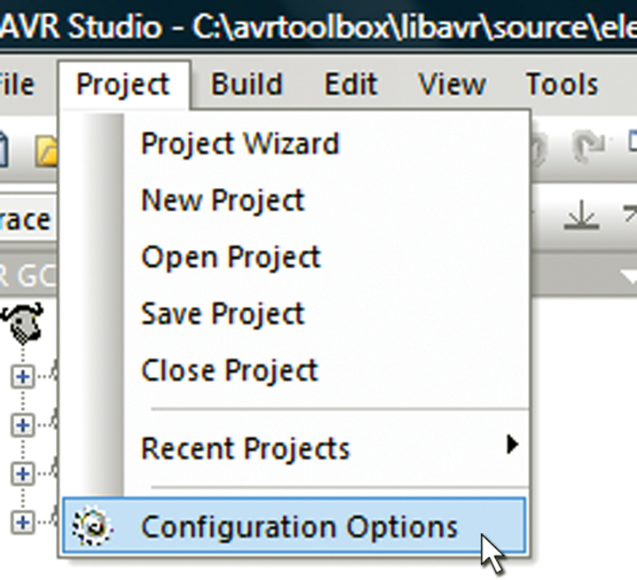
FIGURE 5. Project options.
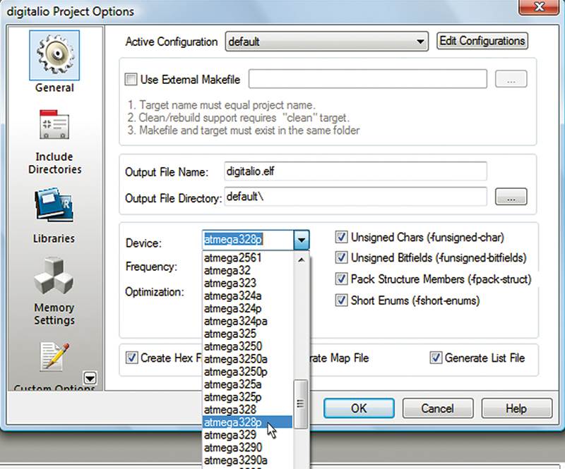
FIGURE 6. Select device.
The line inserted in the makefile is: MCU = atmega328p. This is used under the hood to find the correct header file information to compile and link for that device. If you use a variety of AVRs, you will eventually run into the problem of register or pin naming inconsistencies such that, for example, one device calls pin 0 on port A PA0 while on another device it is called PORTA0.
What they say in io.h is:
Included are definitions of the IO register set and their respective bit values as specified in the Atmel documentation. Note that inconsistencies in naming conventions, so even identical functions sometimes get different names on different devices
What they mean is that nobody was paying attention when the various datasheet writers needed a violent shaking. If you try to move some code that works on one AVR device to another AVR but you get errors or warnings that indicate you are using the wrong register names, this is probably where it comes from and is just another AVR datasheet thing to get used to.
For the ATmega328p, we see that the io.h leads the compiler to iom328p.h. For Port B, you see:
#define PINB _SFR_IO8(0x03)<br />
#define PINB0 0<br />
#define PINB1 1<br />
#define PINB2 2<br />
#define PINB3 3<br />
#define PINB4 4<br />
#define PINB5 5<br />
#define PINB6 6<br />
#define PINB7 7
#define DDRB _SFR_IO8(0x04)<br />
#define DDB0 0<br />
#define DDB1 1<br />
#define DDB2 2<br />
#define DDB3 3<br />
#define DDB4 4<br />
#define DDB5 5<br />
#define DDB6 6<br />
#define DDB7 7
#define PORTB _SFR_IO8(0x05)<br />
#define PORTB0 0<br />
#define PORTB1 1<br />
#define PORTB2 2<br />
#define PORTB3 3<br />
#define PORTB4 4<br />
#define PORTB5 5<br />
#define PORTB6 6<br />
#define PORTB7 7
The first line of these three sets of #defines name the actual register that you will be using for the pin input, data direction, and port output, respectively. In the datasheet, the Registry Summary (as shown in Figure 3) shows these register and pin names in low memory.
A Little Weirdness
Activate Pull-up and Toggle a Pin
There are two operations that you do with the digital I/O registers that don’t make much intuitive sense. First, in order to activate a pull-up resistor on an input pin you write a 1 to that pin. Second, in order to toggle an output pin on the PORTx register you write a 1 to the PINx — the input register. My first response to this was ‘wait a cotton pickin minute ... write to an input, what’s with that?’ However, this bit of weirdness is a clever yet confusing way to avoid having to have another register.
Since writing to an input doesn’t make sense, we can then use that nonsense operation to accomplish two different things: either set a pull-up or toggle a bit. If DDRx for the pin is 1 (input), it sets the pull-up; if 0 (output), it toggles the pin state. I’ve always used the XOR (^) bitwise operator to toggle a bit, but this takes several cycles while writing to the input PINx bit does it as a single atomic operation — an important consideration if you want to toggle a pin at the maximum rate.
Even Atmel must have realized that this is unnecessarily complex because in their Xmega series, they have separate and appropriately named registers for these operations. Since this is so non-intuitive, it becomes a really good item to show off your AVR chops. If you want to take a more humane and neuron-saving approach, then use macros with sensible names. We will take the latter approach and write the macros port_pin_activate_pullup(), port_pin_deactivate_pullup(), and port_pin_toggle() that we will discuss below.
Switching Between Input and Output
It is possible to get problematic intermediate states when changing between certain states:
- From tri-state to output HIGH.
- From input with pull-up to output LOW.
We will take care of this in the digitalio pin_mode() macro which will always deactivate the pull-up and set the output to 0 before setting the data direction to output.
Setting a Pin to Tri-state
This is only odd because it indicates that there is a third state for a binary system which — by definition — only has two states. Tri-state is considered a third state for a pin; the first two being HIGH (Vcc) or LOW (GND). Tri-state means that the pin is disconnected from the voltage and can be considered no longer in the circuit to which it is attached. When the AVR system is reset, the digital I/O pins are in the tri-state condition.
Warning Arduino Pin 13 is Funky
While we are cataloging funkiness, let’s not forget to mention that digital I/O is a bit off on the Arduino pin 13 which is attached to an LED and resistor. This doesn’t have much effect if you want to use it as an output pin, but it does if you use it for input. If you activate the internal pull-up, then the high voltage will be about 1.7V rather than the expected 5V. The Arduino reference states “If you must use pin 13 as a digital input, use an external pull-down resistor.”
Expanding the avrtoolbox Digitalio Library
Now that we have a good idea about the underlying AVR digital I/O architecture, let’s expand our avrtoolbox libavr digitalio toolset to include some more useful functions and macros. We’ll demonstrate this with a chaser light application that reads the digital input from an eight-bit DIP switch and writes the digital output to eight LEDs configured as shown in the figures from last month’s workshop, except that now we will be using ports rather than the Arduino style pins.
Expanded Digitalio Functional Requirements Specification
The digitalio toolset will provide functions or macros to do the following:
- Set a port pin mode to input or output.
- Read a port pin.
- Set a port pin.
- Clear a port pin.
- Activate a port pin pull-up resistor.
- Deactivate a port pin pull-up resistor.
- Toggle a port pin.
Expanded Digitalio Application Programmer’s Interface
port_pin_mode()
Description: Set a port pin mode to input or output.
Syntax: port_pin_mode(uint8_t PORTx, uint8_t pin, uint8_t mode)
Parameters:
uint8_t PORTx: The port as identified in io.h.
uint8_t pin: The pin number 0 to 7.
Uint8_t mode: Either INPUT or OUTPUT.
Returns: Nothing.
Example:
// Set PORTB pin 4 to output
port_pin_mode(PORTB, 7, OUTPUT);
port_pin_read()
Description: Reads the state of a pin in a port.
Syntax: port_pin_read(uint8_t PORTx, uint8_t pin)
Parameters:
uint8_t PORTx: The port as identified in io.h.
uint8_t pin: The pin number 0 to 7.
Returns: HIGH, LOW.
Example:
// Get the pin state
myPinState = port_pin_read(myPort, myPin);
port_pin_set()
Description: Sets a pin in a port to 1.
Syntax: port_pin_set(uint8_t PORTx, uint8_t pin)
Parameters:
uint8_t PORTx: The port as identified in io.h.
uint8_t pin: The pin number 0 to 7.
Returns: Nothing.
Example:
// if myPin is clear, set myOtherPin
if (port_pin_read(myPort, myPin) ) port_pin_set(myPort, myOtherPin);
port_pin_clear()
Description: Clears a pin in a port to 0.
Syntax: port_pin_clear(uint8_t PORTx, uint8_t pin)
Parameters:
uint8_t PORTx: The port as identified in io.h.
uint8_t pin: The pin number 0 to 7.
Returns: Nothing.
Example:
// if myPin is set, clear myOtherPin
if (port_pin_read(myPort, myPin) ) port_pin_set(myPort, myOtherPin);
port_pin_activate_pullup()
Description: Activates the pull-up resistor for a pin in a port.
Syntax: port_pin_activate_pullup(uint8_t ddrx, uint8_t pin)
Parameters:
uint8_t ddrx: The port as identified in io.h.
uint8_t pin: The pin number 0 to 7.
Returns: Nothing.
Example:
// Activate the pullup on PORTB pin 5
port_pin_activate_pullup(DDRB, 5)
port_pin_deactivate_pullup()
Description: Deactivates the pull-up resistor for a pin in a port.
Syntax: port_pin_deactivate_pullup(uint8_t ddrx, uint8_t pin)
Parameters:
uint8_t ddrx: The port as identified in io.h.
uint8_t pin: The pin number 0 to 7.
Returns: Nothing.
Example:
// Deactivate the pullup on PORTB pin 5
port_pin_deactivate_pullup(DDRB, 5)
port_pin_toggle()
Description: Toggles (if 0, sets to 1; if 1, sets to 0) the state of a pin in a port.
Syntax: port_pin_toggle(uint8_t PORTx, uint8_t pin)
Parameters:
uint8_t PORTx: The port as identified in io.h.
uint8_t pin: The pin number 0 to 7.
Returns: Nothing.
Example:
// Force pin 5 to change state regardless of state
port_pin_toggle(PORTB, 5)
Applying Digitalio — Simple Chaser Lights
Last episode, we showed how to set up the hardware for the AVR Butterfly and the Arduino to use the Arduino style numbered pins to do input from an eight-bit DIP switch, and output that state to eight LEDs. The illustrations for the Butterfly had both the pin numbers and the port/pin numbers, but since the Arduino figures did not have the ports shown, we’ll use Figure 7 which shows the port pin numbers with Px for the port followed by the pin number. For example, PD5 is PORTD pin 5. In
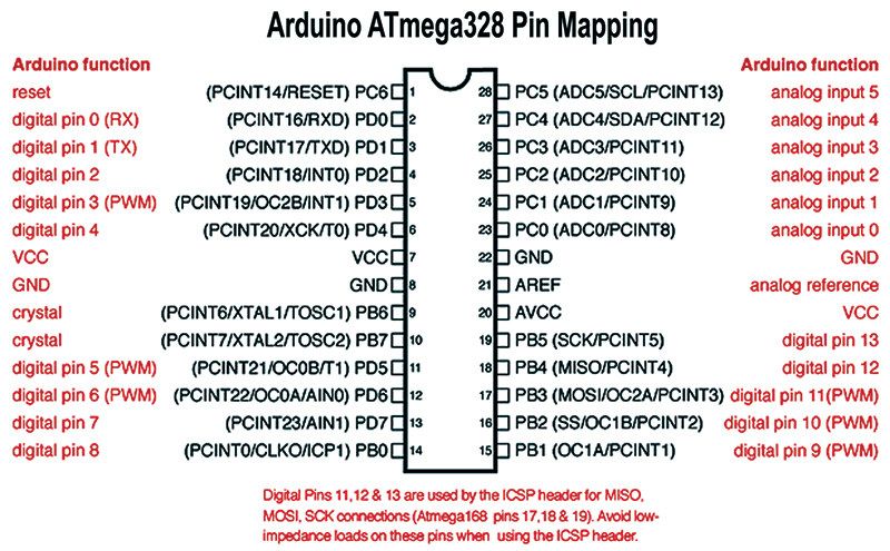
FIGURE 7. Arduino ATmega328 pin mapping.
Figure 8, we see how the Arduino pins relate to the ATmega328 port/pins.
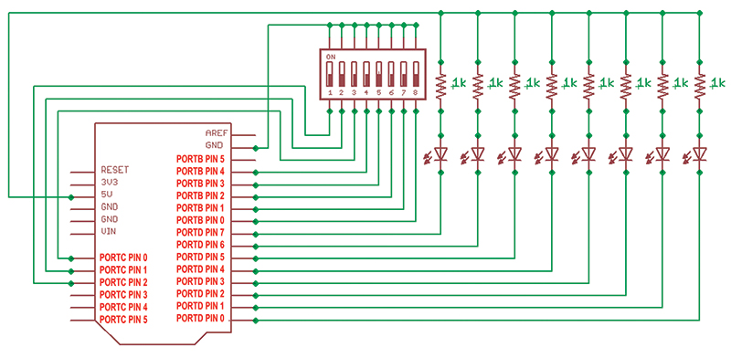
FIGURE 8. Arduino port/pins for DIP switch and LEDs.
As usual, I’ve been having so much fun I wasn’t paying attention to the time. It looks late and long, so let’s put the code in avrtoolbox at http://code.google.com/p/avrtoolbox/avr_applications/simple_chaser_lights. Note that the hardware to do the chaser light project (as shown in Figures 9 and 10) with either the Arduino or the Butterfly is available from the article link. Refer to our last Workshop for more details on how these are wired.
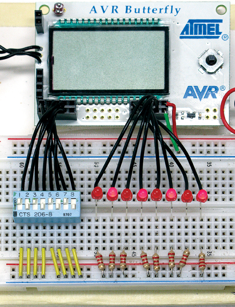
FIGURE 9. Chaser lights using the AVR Butterfly.

FIGURE 10. Chaser lights using the Arduino board.
Final Thoughts
Next time, we will finish up AVR Digital I/O where — if all goes well — I’ll apply it to a breadboardable LCD and keypad project. NV
If you just can’t wait and want to get a leg up on all this serial stuff and real C programming for the AVR, you can purchase my C Programming book and Butterfly projects kit at www.nutsvolts.com.