It's that time of year again! Christmas trees are going up and with all that extra time off, you're going to need a project to work on. How about a circuit that will make it easy to check if the water reservoir in your tree stand needs to be filled or not? I thought I'd use this tree-checking problem as a reason to review voltage dividers and the R-2R ladder, and also do a bit of circuit analysis.
Let’s plan on using a simple indicator of the water level: a voltmeter. We’ll need a circuit that outputs a voltage that is somehow related to the depth of water in the reservoir. Hmmm ... but how?
I claim it can be done by placing a positive lead at the bottom of the water reservoir, followed by three (or so) wires at incremental depths, up to the top of the reservoir as shown in Figure 1.
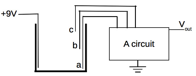
FIGURE 1. Schematic of proposed water-level measuring device. The"live" nine volt wire can be connected to "depth wires" (a), (b), and (c) via water of sufficient depth.
Here, a 9V battery will feed the positive lead at the bottom of the reservoir. The other three wires — called “depth wires” (a, b, and c) — will be used to determine the water level. As water sits in the tank at varying depths, a charge from the 9V wire will conduct through the water into any depth wire submersed in the water (the depth wires ultimately lead to the battery’s ground in the circuit). We’d like to feed all three depth wires into a circuit whose job is to present a voltage on the Vout wire; that will indicate the depth of the water in the reservoir.
To check the tree’s water level, we’ll turn on our voltmeter, push a momentary switch to turn on the circuit, check the voltmeter reading, then decide if we need to add water or not. So, what circuit can be built that can take input from three wires and output a voltage that is somehow related to the particular depth wire and be connected to 9V?
The Voltage Divider
As we figure out what the circuit should be, let’s first review the voltage divider shown in Figure 2.
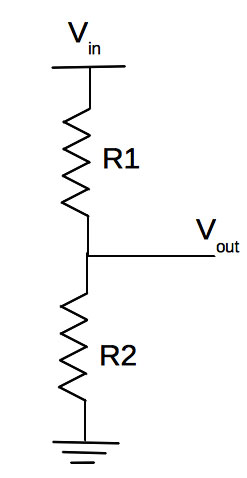
FIGURE 2. The classic voltage divider. Vin is some input voltage. Vout will be some fraction of Vin, depending on the values chosen for R1 and R2.
It is commonly known that Vout will be Vin x R2/(R1 + R2). In other words, the resistors scale the input voltage (Vin) at their connection point, down by the factor of R2/(R1 + R2). Vout is always less than Vin (since R2 is always less than R1 + R2), hence the name “voltage divider.”
As an example, if Vin = 9V, R1 = 100Ω, and R2 = 500Ω, then the factor will be 500/(500 + 100) = 0.83, or Vout will be 0.83 x Vin or 7.5 volts. So, how does this actually work? What is the “secret life” of a voltage divider?
One of the stipulations of a working voltage divider is that whatever Vout is connected to cannot consume very much current, compared to that rushing from Vin through R1 and R2, and on into ground. The current between Vin and ground can be found from Ohm’s Law, which is I = V/R. Since R1 and R2 are in series, the total resistance they present between Vin and ground is R1 + R2, or 600Ω (using the numbers above).
So, the current flow will be I = 9V/600Ω = 0.015 amperes (A). Thus, 0.015A leaves the battery at 9V; it then encounters R1, which presents it with 100Ω of resistance. Passing through the resistor will lower the voltage of the current by (using Ohm’s Law again) V = (0.015A)(100Ω) = 1.5 volts. Thus, when the current enters R1, it will be at 9V; when it exits R1, its voltage will be lowered by 1.5V, down to 9V - 1.5V = 7.5 volts, which is the same prediction as the voltage divider equation above. So, a voltage divider works by the action of resistors lowering the voltage of current that passes through them. Keep this in mind as we go back to our tree water problem.
The Circuit
The circuit we’ll route the three depth wires into is shown in Figure 3.
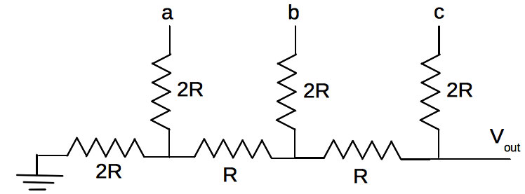
FIGURE 3. An R-2R ladder.
Wires (a), (b), and (c) from the tree reservoir will be connected to points (a), (b), and (c) in this circuit. The circuit is called an R-2R ladder for obvious reasons: vertical resistors of resistance 2R, separated by horizontal resistors of resistance R.
Motivated by our need to measure a water level and with our knowledge of voltage dividers, let’s see how this circuit works. Let’s use R = 1,000Ω, which makes 2R = 2,000Ω.
Suppose the water level has just covered wire (a) in Figure 1. In the circuit, this means (a) will be at 9V and the circuit will behave as if everything to the right of the vertical resistor connected to (a) isn’t even present (since b and c aren’t connected to anything). If you think at least the 1K resistors should still be in the circuit, you are sort of right, but we’ll say no to this for now.
The voltmeter attached to Vout draws almost zero current, so virtually no current will flow through the 1Ks, and by Ohm’s Law again, the voltage drop across them will be V = IR. However, with I = 0 (or nearly so), the voltage drop across either is zero. Thus, the circuit will resemble Figure 4.
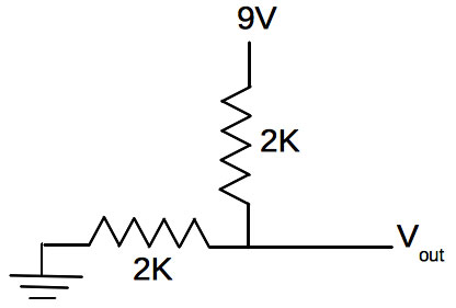
FIGURE 4. The R-2R ladder from Figure 3, as it would behave if only wire (a) was connected to 9V.
Looking at it carefully, you’ll see that it is similar to the voltage divider with equal resistors. Thus, Vout will read 4.5 volts, and we have our first water level to voltage mapping. In fact, if you read 4.5 volts, the water level is low — you might want to add some water to your reservoir.
This is something about voltage dividers worth remembering: If they are built with two equal resistors, the voltage at the connection point of the resistors will be half of the supply voltage.
What if the water is covering both wires (a) and (b)? The circuit will now look like Figure 5.
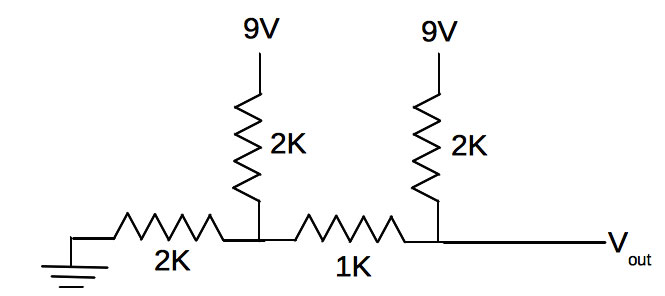
FIGURE 5. The R-2R ladder from Figure 3, as it would behave if wires (a) and (b) were connected to 9V.
So, how can we figure Vout now? Well, notice in Figure 5 that (a) and (b) are now both connected to 9V (through the water), so why not rearrange the circuit a bit? We’ll tie (a) and (b) together; imagine them connected to a single battery which we’ll draw toward the left, while being careful that ground is still on the left end of the 2K resistor. The result is in Figure 6.
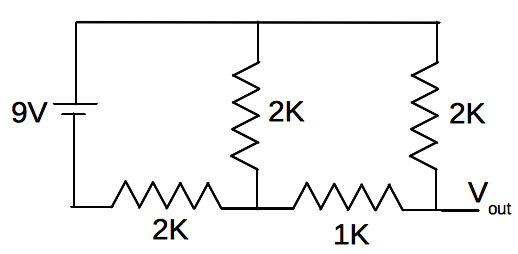
FIGURE 6. The circuit in Figure 5, rearranged to make analyzing it a bit easier.
Now, again assuming that the voltmeter connected to Vout draws no current, we see that the 2K and 1K on the right are in series. We can combine them into a single 3K resistor, and our circuit becomes Figure 7 (A).
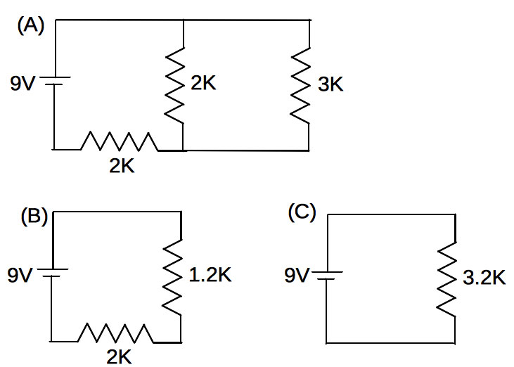
FIGURE 7. (A) is Figure 6 with the rightmost 2K and 1K combined into a single 3K resistor; (B) is circuit (A) redrawn with the parallel 3K and 2K resistors combined into a single 1.2K resistor; (C) is circuit (B) redrawn with the series 1.2K and 2K resistors combined into a single 3.2K resistor.
Now, we see the 2K and 3K are in parallel, so they can be combined into a single 1.2K resistor as in Figure 7 (B).
Lastly, the 1.2K and 2K are in series, and can be combined into a single 3.2K resistor as in Figure 7 (C).
Why go through all of this? Because the 3.2K resistor represents the total resistance the R-2R ladder presents to the battery when both wires (a) and (b) are submerged. From this, we can find the total current the 9V battery is supplying to the circuit. From Figure 7 (C), it’ll be (from I = V/R) I = 9V/3200Ω = 0.0028 A.
Going back to Figure 7 (B), since the 3.2K (which is carrying 0.0028A) came from the 1.2K and 2K in series, both of these will also carry 0.0028A.
Now, here’s where we apply our knowledge of the voltage divider from earlier. Since 0.0028A is flowing through the 1.2K, it drops the voltage of the current by (using Ohm’s Law) V = 0.0028 x 1200 = 3.38V. However, the 1.2K — with the 3.38V drop across it — came from the 2K and 3K in parallel in Figure 7 (A).
Thus, there’s a 3.38V drop across both the 3K and the 2K.
Lastly (bear with me), since the 3K came from the 2K and 1K in series (from Figure 6), the 2K and 1K in Figure 6 must have 3.38V across them as well.
Finally, here’s the clue to what voltage we’ll get from our tree water level sensor if both wires (a) and (b) are submerged: Having 3.38V across the 2K and 1K will mean a current of I = 3.38/3000Ω = 0.0011A will flow through them.
Now looking carefully, you’ll see the top of the 2K resistor is at 9V and the bottom is where our voltmeter is connected. Hence, our voltmeter is measuring the drop (from 9V) in voltage across the 2K, which will be 9V - 0.0011 x 2000 = 6.74V. Thus, the voltmeter will read 6.74V when the water covers wires (a) and (b).
All told, you can see where this is going. We get 4.5V when just wire (a) is submerged. Now, we’re getting 6.76V when the water is deeper and wires (a) and (b) are submerged. We won’t trouble you with the calculations to figure out the voltage when (a), (b), and (c) are submerged. (Wasn’t doing just (a) and (b) bad enough?) Suffice to say, it’ll be a higher voltage.
While checking all of this work using Falstad’s circuit simulator (www.falstad.com/circuit), I found that the circuit outputs 7.88V when all three depth wires are submerged. So, we have it then: a circuit that will output a voltage proportional to the water depth in our reservoir.
The deeper the water, the higher the output voltage.
Let’s build it now and see what we get.
In Practice
There is really nothing critical about the wiring or construction for this project. I started by wiring the tree holder as shown in Figure 8 using 22 gauge hookup wire (I drilled some small holes near the top rim to hold the wires).
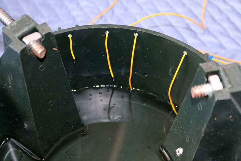
FIGURE 8. Placement of the positive 9V lead (rightmost) and three depth wires in a standard tree stand.
In this figure, you can see the three depth wires going from left to right. My positive 9V lead is the rightmost one. Be sure to strip about 1/8” of insulation off of each wire.
Next, I breadboarded the R-2R circuit as shown in Figure 9.
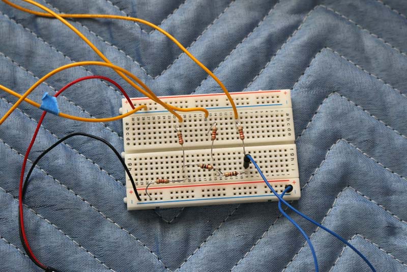
FIGURE 9. Breadboard R-2R circuit. The yellow wire with the blue tape is the 9V positive lead. The red and black wires are from the 9V battery clip. The two blue wires are feeding the voltmeter.
I only had 2.2K resistors in my parts bin, so my ladder is made from 1K and 2.2K resistors. I used a 9V battery clip to connect the battery to my circuit. The yellow wire with the blue tape on it is the 9V wire feeding the reservoir. The other three are the depth wires. My final assembly is shown in Figure 10.
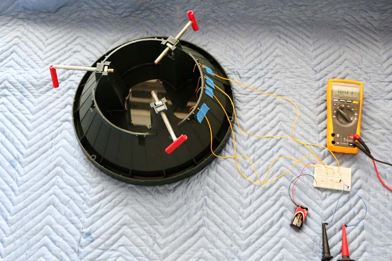
FIGURE 10. Final assembly of a circuit that will output a voltage proportional to the depth of the water in the reservoir.
When run, I get 1.8V when the lowest wire is submersed, 2.9V for the next wire, then 3.5V when all three wires are submersed. This is different than our previous calculations, but the big variable here is the resistance of the water. Probing the water quickly with my meter reads 6.3V near the hot wire and 5.7V near the other wires (both not 9V). Either way, we have an unambiguous voltage linked to the depth of the water in the reservoir.
A final version of this project would have the circuit board perhaps soldered together and mounted into a project box. Long wires would allow the voltmeter and a small pushbutton (that turns the positive lead on) to be positioned at a location that obviates the need to crawl on the floor, pushing presents aside to check the water level.
Final Thoughts
Certainly, LEDs could have been turned on by each wire as each became submersed (maybe a red, yellow, and green one, etc.), but I wanted to wrap a bit of circuit analysis into this article, which I hope you were able to wade through. The two-input case presented here would be considered a “difficult” problem to analyze for freshman science majors I teach at my university.
The idea that resistors drop the voltage of current that passes through them is a core concept in electronics, and provides a context for realizing that indeed voltage, resistance, and current (and power, energy, etc.) are all different quantities in electronics. In this case, Ohm’s Law relates voltage, current, and resistance via V = IR, and you saw two different uses of it: one to calculate a current, and the other to find the drop in voltage a resistor causes.
The astute reader will realize our original problem was really one of a digital-to-analog conversion. The digital inputs are the depth wires — either “energized” when submersed (a true state), or unconnected (false) when in the air. Our need was to map different combinations of depth wire true/false states into a unique voltage. Indeed, R-2R ladders are analog-to-digital converters.
Lastly, if you need more depth resolution, you could simply add more wires and more sections of R-2R pairs. Also, having the information (depth, in this case) as a single voltage allows for many interfacing possibilities, such as sending our depth voltage into the analog input of an Arduino, for example (be careful to keep it under 5V though).
Happy holidays! NV
Parts List
| Item |
AllElectronics.com Part# |
Price |
| 20 gauge hookup wire |
20YL-25S |
$3.77 for 25' |
| 9V battery clip |
BST-81 |
$0.55 |
| Breadboard |
PB-400 |
$4 |