Preserving a piece of stereo history, a tube console stereo repair story.
Vintage gear is really special. There's just nothing like the unique sound, look, and feel of an old tube hi-fi glowing away and playing your favorite record. Unlike a lot of modern gear, they can still be worked on and fixed up by a dedicated hobbyist.
I’m lucky to get to see and work on a lot of vintage radios and stereos at my small shop in Seattle, where I repair all kinds of gear from early tube radios going up to the modern era. This 1963 Zenith hi-fi stereo console is one of my favorites. The classic styling would look great with modern accents, too — it would look just as good with a flat-screen TV on top instead of a typewriter, and could even play its audio.
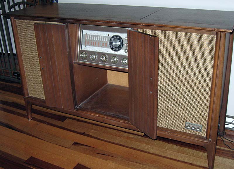
FIGURE 1. The patient: Zenith's MK2670 stereo console.
This was a top-of-the-line piece in its day, built by hand in the USA with precision electronics, carefully selected speakers, and a heavy wooden console cabinet made to be a prominent piece of furniture in the home. With a total of 19 tubes, it could really heat up a room.
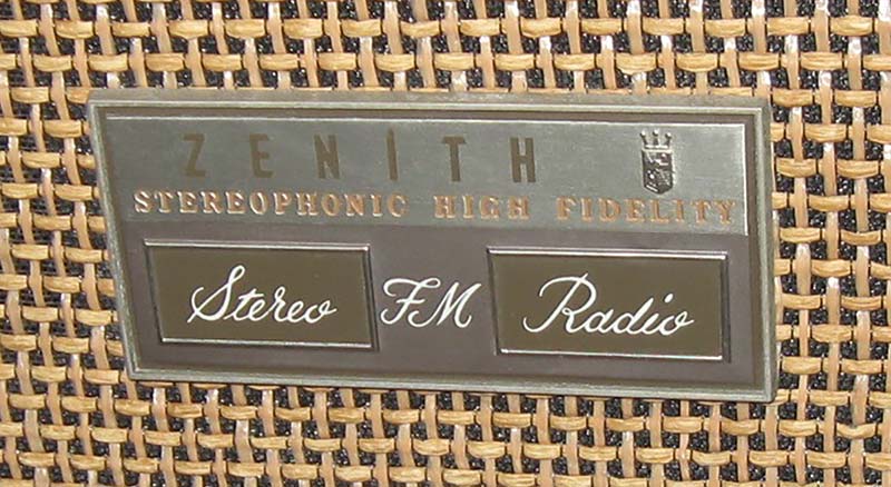
FIGURE 2. "Zenith: the quality goes in before the name goes on."
This particular model came with a pair of efficient, fantastic sounding three-way speakers with powerful magnets driving a 12” woofer, twin smaller cone midranges, and a horn tweeter. When running properly, it sounds lively and musical — so when it started to sound worse and worse and take a longer and longer time to warm up, its owner knew something was going wrong. I made a house call to remove the guts; there were two big metal chassis: one for the amplifier and power supply; and a second for the tuner and pre-amp.
A Word Of Caution
Don't just plug in a piece of vintage gear you find to see if it works! This can be dangerous and might cause a fire or shock, depending on its condition. Solid-state gear after about the mid '60s can be powered on safely to see if it hums or makes any sound, but most tube gear from the early '60s and before probably needs service before it will work safely and reliably. Early electronics used parts which break down with age just sitting on a shelf, and it only takes a few seconds for something to go seriously wrong and burn up an important component.
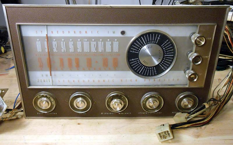
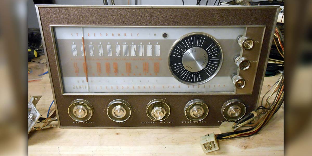
FIGURE 3. What a beautiful space age dial!
The front control panel is a masterpiece of space age design. It looks like the control panel of an old rocketship. I think that’s one of my favorite things about this stereo. It has quite a few functions: there’s the function selector on the left; the tuner, loudness, and balance on concentric controls in the middle; the stereo function switch; the power switch along the bottom; and along the side, separate treble, bass, and presence controls. It’s fully customizable.
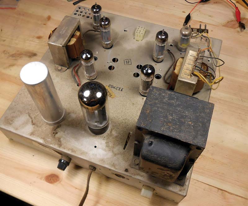
FIGURE 4. The amplifier chassis model 7K31.
Digging into the Repair
The amplifier chassis — hidden inside the cabinet — is a lot more minimal. There’s the output tubes: a pair of 6BQ5s for each left and right. You might know them as EL84s, and in this amp they produce a nice clean sound with plenty of power for the efficient speakers they’re driving.
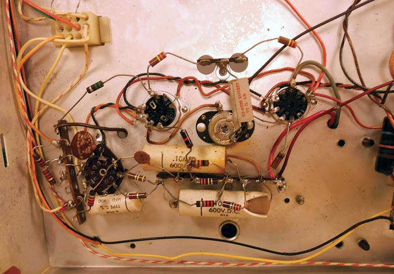
FIGURE 5. Wiring around one amplifier channel's output tubes.
It’s pretty chaotic underneath. By this time, they’d invented printed circuit boards but they hadn’t taken over yet, and many consumer electronics just used good old fashioned point-to-point wiring. It works, but it can look like a hot mess! With the components spaced so far apart, though, it’s easy to give it a quick look-over for obviously bad parts — and there’s a problem that shows up right away.
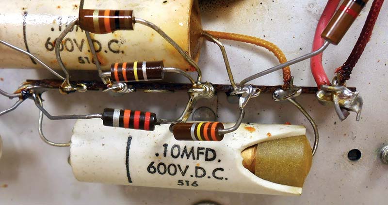
FIGURE 6. This capacitor blew a piece of casing clean off.
This capacitor is attached to the power amplifier circuit — and it’s blown a piece of its plastic casing clean off! Modern capacitors are made of durable and reliable materials — often plastic and metal films and ceramics. Back then, though, these materials had just started to become available, and most electrical components were still ultimately made of paper and foil with special packaging. This one used a plastic and epoxy package but over 50 years, the paper and foil degrade and start to leak electricity. This creates a heat build-up that can release gasses which expands in the sealed body, and ... pop! Off goes a piece of plastic.
Even with this failure, the amp continued to try and play — vintage gear can really take a beating. Once the parts get to this stage, though, there’s no sense in just replacing a few. They’re all the same age and they’re all going bad, even if a few have somehow survived this long. It’s time for a complete overhaul to make sure it stays a great performer for a long time to come (Figure 6).
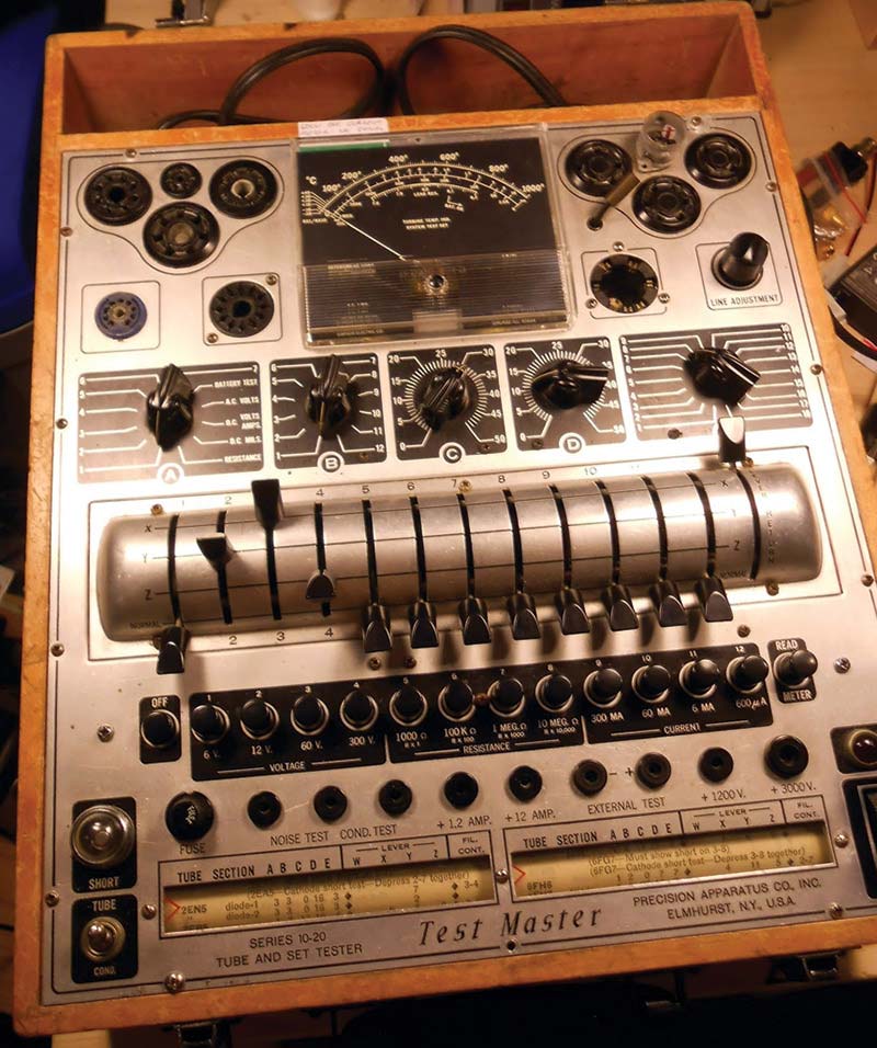
FIGURE 7. The Precision 10-20 tube tester.
It’s handy to have some special equipment for working on tube gear, but you don’t really need much more than a soldering iron and multimeter to take care of most of the basics. In this case, though, I started off testing the tubes; a few in the radio needed to be replaced but most were good. This radio was handed down from the current owner’s parents, and they’d looked after it over the years, replacing some of the power tubes as they’d worn out, but most of the others were the original Zenith parts.
The resiliance of tubes
Tubes were designed to last a long time, and they don't generally go bad on a shelf. So, unless it was just rode hard and put away wet its entire life (or hit by a power surge), most of the tubes you find are likely to be good. Some tubes which develop a white coating inside have lost their vacuum over the years, but most will probably be in good shape. Even if not, you can track down new old stock replacements for most tubes without too much trouble.
Safety First
As with all electronics projects, take proper safety precautions while servicing a vintage radio or stereo. General precautions always apply, but tube electronics run on much higher voltages than solid-state gear, plus tubes get extremely hot while operating. Be careful of unsafe vintage wiring schemes that put mains voltage on exposed bare metal parts of the chassis like control shafts. Go slow and be careful!
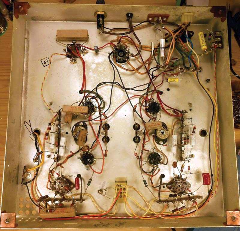
FIGURE 8. Underside of the 7K31 amplifier after replacing the bad capacitors.
I went slowly, replacing the components as close to their locations as possible. Old capacitors were usually made of paper and foil; old carbon composition resistors tended to absorb moisture from the atmosphere over the years and change in value. Resistors which dissipate more power and put out more heat tend to have it worse.
I tested a sampling of the resistors to check their tolerance, paying special attention to the bias resistors. Only a few had drifted past their marked tolerance bands and needed to be replaced. Zenith picked good quality parts when they built this originally. Most of the resistors were stable, even over more than 50 years.
The amplifier and power supply were great to work on, with a ton of room and a clean easy-to-follow layout. The tuner and pre-amp chassis was a different story. It’s a densely packed multi-layer maze of different construction resistors and capacitors, mixed in with a few coils and sockets for good measure.
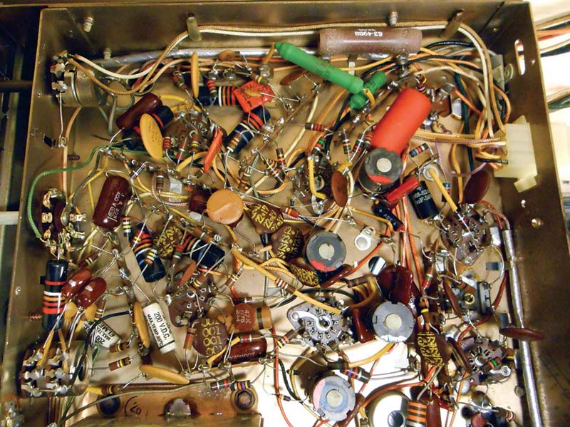
FIGURE 9. The chaotic underside of the 12K25 tuner chassis.
Zenith mixed and matched a few styles of capacitors while building this, which makes it a bit tough to tell if something is a replacement or original. There’s the “black beauties” — the black cylinders with color bands similar to a resistor. There’s more of the epoxied plastic paper capacitors in white; a handful of classic cardboard capacitors; and a handful of assorted early film or paper/mylar caps — not to mention two styles of disc capacitor, and several mica “domino” rectangular capacitors.
I had to work with needle-nose pliers in each hand for most of the tuner section repairs to thread the parts exactly where they were originally. These high performance circuits were sensitive to positioning, so even changing where the wires run or the components hang can cause problems with reception and feedback.
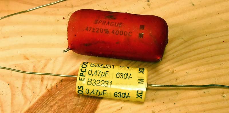
FIGURE 10. There's a big size difference between vintage and modern capacitors!
The tuner section had a mix of older style and newer style capacitors. The Sprague is probably a coated paper model; I always make sure to replace ones like that when I see them so they don’t cause problems later on.
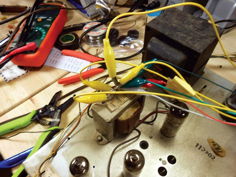
FIGURE 11. A rat's nest of test leads connects the amplifier to a set of test speakers.
Most tube amplifiers used output transformers to connect to the speakers. Zenith ran the leads for both speakers to a terminal strip on top of one transformer with convenient color-coded labeling. One thing that’s pretty unusual about this Zenith is the output transformers had separate windings for different drivers. The 12” woofers are on their own secondary from the horn and midrange drivers.
I’ve run into a few Zeniths which used a similar scheme, but I’ve never seen another manufacturer do this. (Feedback windings and matching taps are pretty common — but multiple driven secondary windings seem to be pretty rare!)
Finishing Up
I hooked up a whole mess of clip leads to four bench speakers for testing since I’d left the original drivers mounted to the cabinet. With resistors and capacitors replaced, it’s safe to run the stereo for the rest of the process: alignment, bias adjustment, and burn-in testing. I started with the bias adjustment since that will ensure safe amplifier operation and good sound quality through the rest of the process.
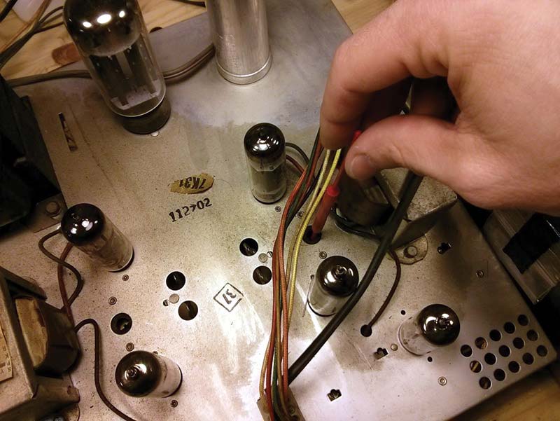
FIGURE 12. Adjusting the bias on one of the stereo amplifier channels.
In this photo, I’m adjusting the bias potentiometers. I hooked my multimeter up to the underside while making these adjustments since (at the time) I didn’t notice the convenient top side test points they provided. Oh well! Both channels were really pretty close already, but I tweaked them to perfection for good measure. With the amplifier section sorted, it was time to move on to the tuner alignment.
For a receiver, alignment is the process of adjusting the tracking and reception of the tuned circuits for the best performance. If you’ve ever owned an older piece of gear like an FM radio, you know that sometimes the dial indicator can get out of sync with the stations, making them come in at the wrong locations on the dial. Sometimes, components drift and settings change, and this can cause distortion in the audio or weak reception. With an accurate signal source, you can adjust the tuned circuits in the receiver to bring everything back to where it should be.
Alignments can be a bit tricky. There are several adjustments to make in an alignment for a receiver like this one since there are separate adjustments for every stage for both AM and FM independently. In all, the radio needs the antenna, front end RF amplifier, dial tracking on both the high and low sides, and the intermediate frequency stages all to be re-tuned. Plus, on the FM side, there’s a series of additional adjustments for the stereo functionality. All told, there’s eight RF transformers in this radio, plus four coils used in the FM stereo de-multiplexer.
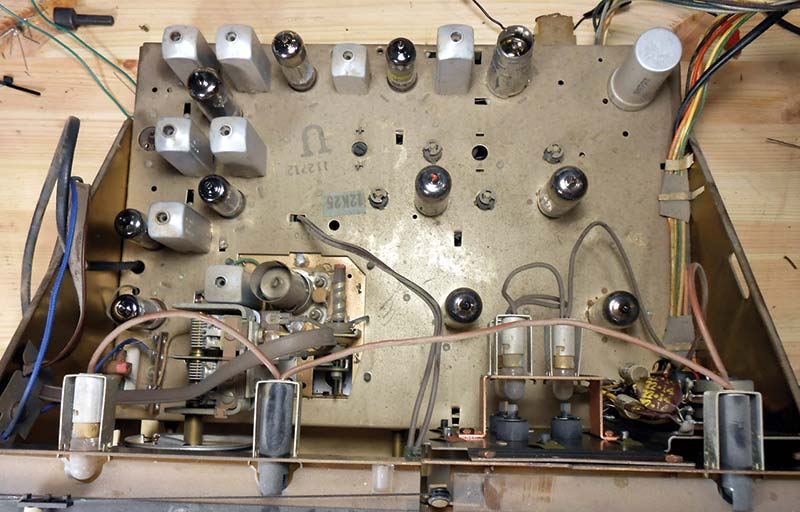
FIGURE 13. The tuner chassis showing all eight of the RF transformers to adjust.
It’s fairly easy to do an AM alignment “by ear” using nothing but an adjustment wrench and whatever broadcast stations you happen to be able to receive with a short antenna. AM radio is a very simple technology that’s been around over 100 years, so there’s really not much to it in most cases.
An FM alignment is a lot more challenging, though. It’s possible to do an FM alignment with a multimeter and an AM signal generator (and a fair amount of patience), but for best performance you generally need a sweep signal generator or an FM signal generator and an oscilloscope in addition to the multimeter. Trying an FM alignment by ear usually doesn’t turn out well.
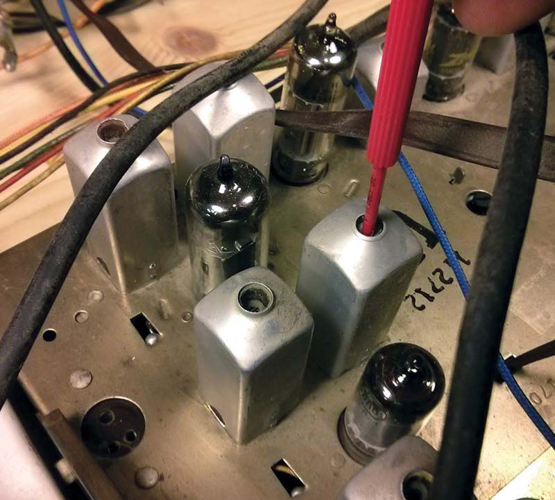
FIGURE 14. Adjusting one of the RF transformers with a non-inductive alignment tool.
Since there’s so many adjustments, I didn’t take a photo of each individually, but I did a full AM and FM alignment. The AM side only needed minimal adjustment as it was coming in pretty close. The FM side was still in great shape, needing just minor adjustments to bring it back to full performance. Miraculously, the FM stereo tuning was in perfect shape and didn’t need any adjustment at all. Zenith’s quality really showed here; the adjustments stayed solid for 50 years.
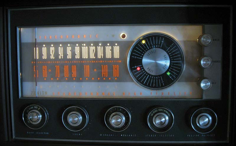
FIGURE 15. All lit up like the cockpit of a space ship.
All told, this vintage hi-fi stereo console took quite a bit of work to clean up, but it turned out fantastic. I replaced a few burned out light bulbs on the dial to make it really shine. It was a real shame when I had to take it back to its owner after letting it play on my bench for its burn-in period. It sounded so nice!
I removed quite a few bad parts from the amplifier and tuner while it was on the bench: resistors, capacitors, bulbs, and a couple of tubes which tested bad. It looks like a handful all laid out.
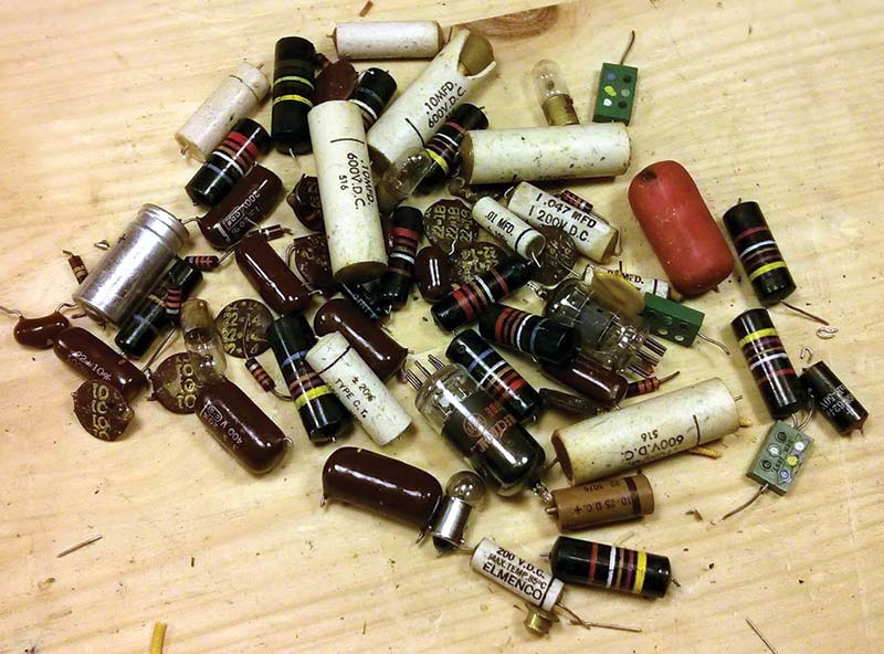
FIGURE 15. Out with the old, in with the new!
It took me about 24 hours of working time, plus a few more for research and testing to bring this unit fully back to life. With the new parts and tubes and a full alignment, it’s back to playing as good as it did when new, and it will continue to be a great décor piece and functional stereo for many years to come. NV
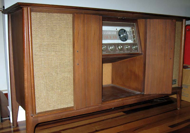
FIGURE 16. Home sweet home.
Unchanging Technology
Guglielmo Marconi developed the first commercial radio system in 1894, but it wasn't until 1906 when Reginald Fessenden and Lee de Forest developed Amplitude Modulation (AM) that radio started to explode, and it didn't make it into most households for another two decades. The technology is mostly unchanged since then. A radio made back in 1924 will happily tune in one of today's AM stations.