Last time, we continued our series on an Arduino handheld prototyper that — as the name implies — lets us develop prototypes that are portable in our very own hand. I'll admit it. I've been having too much fun with this prototyper. This thing lets me do Arduino development using a PC (as usual) but also lets me get input from pushbutton keys, plus produce visual output on an LCD — all in a compact portable framework. Gone are the days of having the bits and pieces scattered around on a table, hooked up to a PC. Now, I can just grab the whole thing and take off.
Fresh Air Controller for a Castle
I was in the midst of developing the handheld prototyper when a friend who lives nearby asked me to help him use an Arduino to develop a fresh air controller for his castle. (Well, it’s certainly close enough for these parts.) It's got a courtyard (Figure 1), a great room, suits of armor, a broadsword next to a fireplace you could roast a dragon in, plus gargoyles (Figure 2).

FIGURE 1. Castles have courtyards.

FIGURE 2. What's a castle without gargoyles?
Joel Fairstein owns this particular castle and does some outstanding tinkering, so he decided to do a project to help heat and cool his place. This is a perfect application for our handheld prototyper — even if you don't own a castle.
Figure 3 shows the prototyper set up as a fresh air controller;
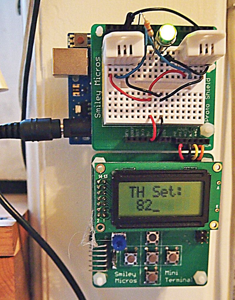
FIGURE 3. Fresh air controller prototype.
Figures 4 and 5 show the vent boxes Joel designed that have an aerodynamic vane that gently opens when the attic fan turns on, then closes to keep out the rain when the attic fan shuts off. Of course, they have a bug screen to keep out the critters at all times.
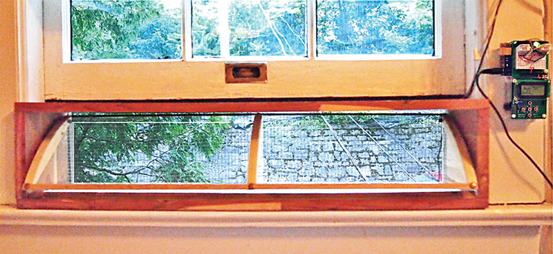
FIGURE 4. Inside view of a vent box and the controller.
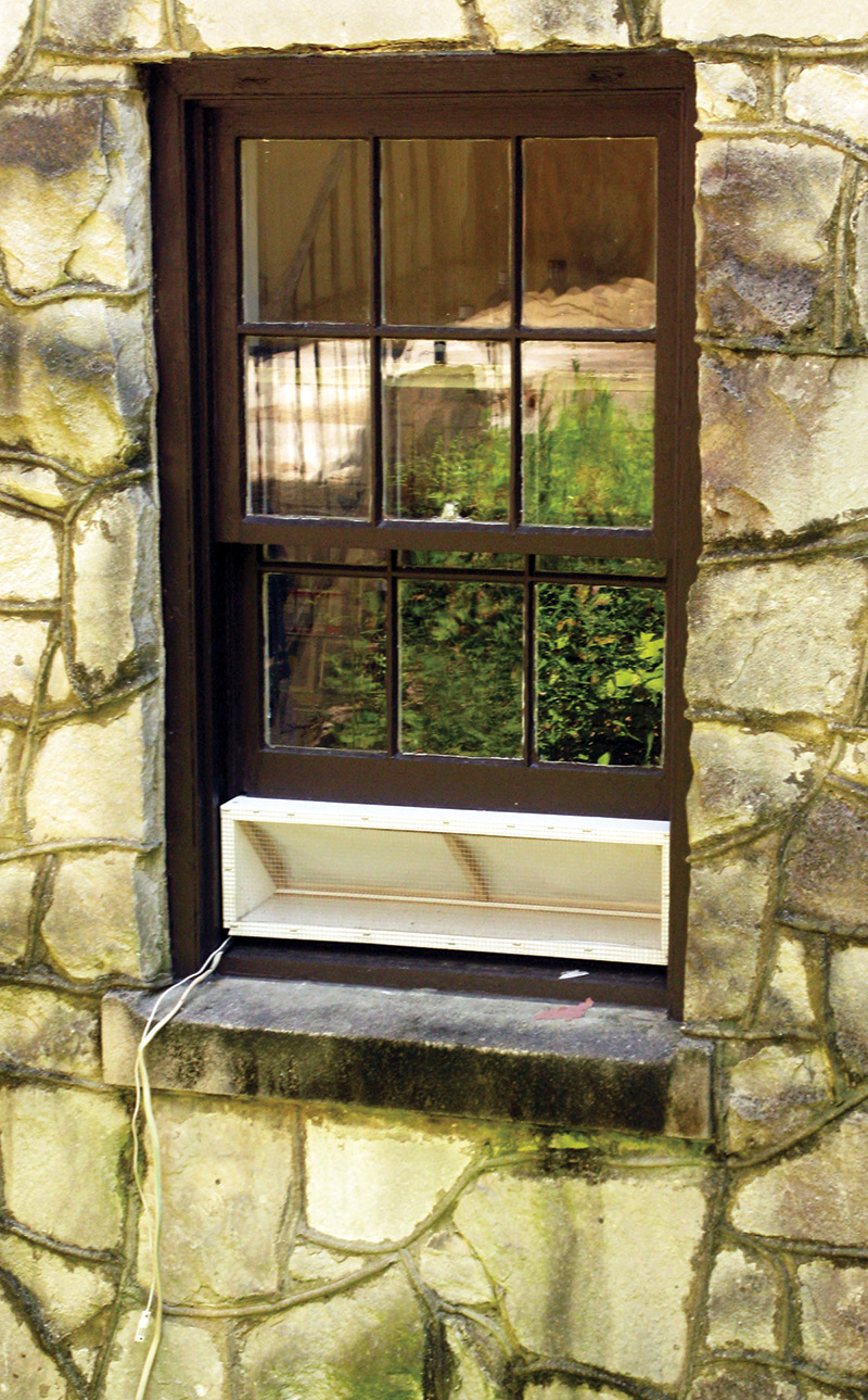
FIGURE 5. Outside view of a vent box.
These vent boxes are easily removable for those times of the year when it is just too hot or cold outside to warrant using this system.
The fresh air controller relies on us having accurate measures of indoor and outdoor temperatures and humidity, so we'll know when to turn the attic fan on and off. Let's look at measuring these parameters and the sensor we will be using.
Sensing Temperature and Humidity
Relative Humidity
Humidity tends to be important to our comfort. You can feel cooler in Death Valley at 105° than you might feel in a Louisiana swamp at 85°. The reason is that we sweat to cool off. For sweat to work, it has to evaporate. If the air is dry, it can evaporate quickly; if the air is very humid, it might not evaporate at all.
To use a modest simplification: The amount of water vapor that air can hold depends on the air temperature. Warmer air can hold more water vapor than cooler air. This is why it tends to rain when a warm front with a lot of moisture runs into a cold front. The warm air cools down and the water vapor condenses into liquid that drops out of the sky.
We use the term RH (Relative Humidity) to mean the amount of water vapor (humidity) that may be present at a given temperature before the air becomes saturated and water begins to turn to liquid — the dew point.
An RH of 100% means that the air is saturated, while 0% means there is no water vapor present. People tend to be most comfortable at an RH between 30% and 70%.
Measuring RH
In order to measure RH, we need to not only sense the water vapor pressure but we need to sense the temperature, as well. There are many ways to do this, but the most common inexpensive way this is done is with sensors such as the DHT22 (Figure 6) that outputs a digital signal that we can read for the RH and temperature.
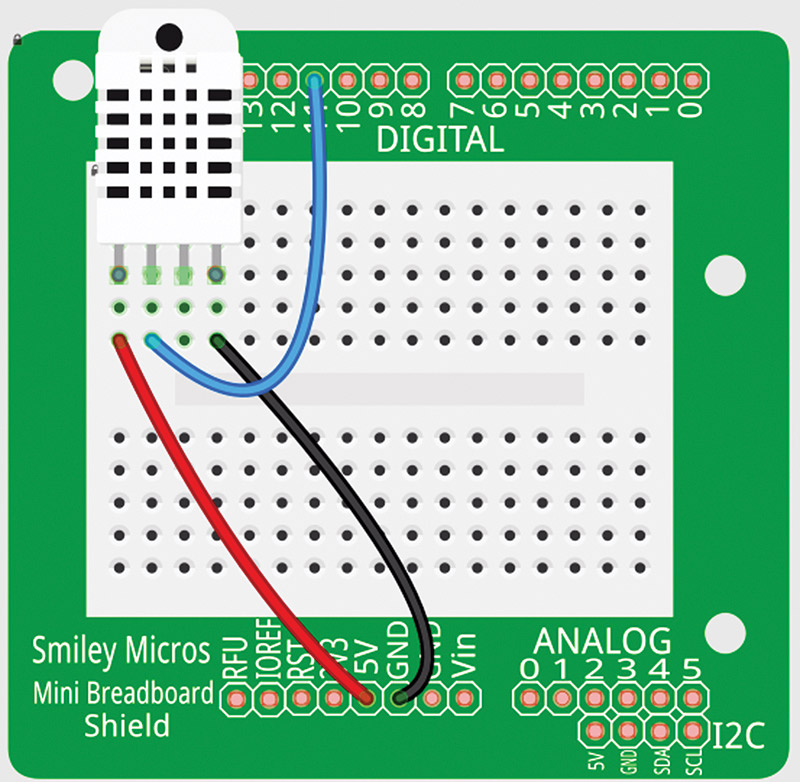
FIGURE 6. Fritzing breadboard view.
In practice, we can read this sensor about once every two seconds and expect to get an RH reading that is ±1% accurate. The digital signal output is somewhat arcane, but fortunately we have access to pre-built and tested libraries to use with the Arduino.
Temperature
Temperature is a measure of how hot or cold an object is; we measure temperature with a thermometer (duh). The DHT22 uses a thermistor (thermal resistor) which is a type of resistor that has a resistance that varies significantly with temperature. As with the RH, the temperature is reported as part of the digital data output of the DHT22. The temperature reading is accurate to ±0.36 Fahrenheit.
Using the DHT22 Hardware
There are lots of ways to sense temperature and humidity. We will use the DHT22 [you can get one from Adafruit or Virtuabotix for about $13]. This sensor is a bit more expensive than its DHT11 little brother, but it is also more precise, accurate, and has a better range for temperature/humidity.
It is absolutely critical that you pay attention here because you can very easily kill your $13 DHT22 if you wire it wrong.
Design for DHT22 With Fritzing
Let's look at how to use Fritzing to design a circuit with the DHT22 on the Arduino proto shield. You can refer to previous Workshops to see how to do this. You can get the Fritzing component for the DHT22 from http://learn.adafruit.com/using-the-adafruit-library-with-fritzing/download-the-fritzing-library-from-github. Sorry about the long URL, but Adafruit is a good place to get the DHT22. They also have their own Arduino library for this part. However, we will use the aforementioned Virtuabotix library (it worked better for me) since you can also get a DHT22 there.
We see the Fritzing component in the breadboard view in Figure 6; the schematic view in Figure 7; and the printed circuit board (PCB) view in Figure 8.
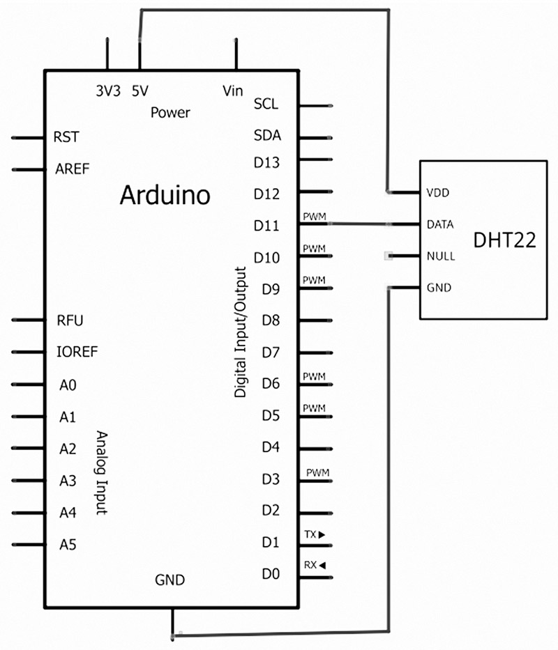
FIGURE 7. Fritzing schematic view.
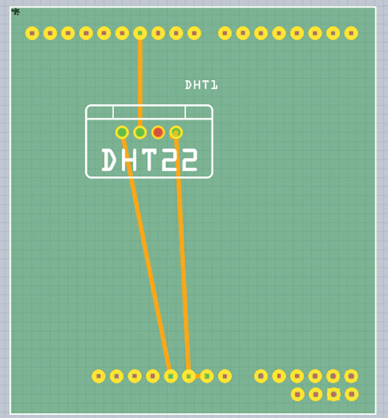
FIGURE 8. Fritzing PCB view.
Note very carefully how this is wired. Make sure that you don't miswire this device because (as mentioned) you can kill it if you do. The Adafruit tutorial recommends a 10K pull-up on the data line, but I found it was not needed in this application.
Test It With the Arduino
As mentioned, we will use the DHT22 Arduino library written by Joseph Dattilo of Virtuabotix (another good reason to buy your DHT22 from them). The link to get this code is www.virtuabotix.com/core/wp-content/uploads/2012/09/DHT22_1S0A.zip.
Since this is GPL, I've included it in the FreshAirController.zip download that you can get from the article link.
To use this library, unzip the DHT22_1S0A.zip file and then copy the DHT22 directory to your Arduino libraries directory. In my case, this was C:\Arduino-1.0.4\libraries. If you have the Arduino integrated development environment (IDE) open, you will need to close it and reopen it so that it will find the library.
The Virtuabotix library has some examples that we can use to test this design. Open the Arduino IDE, then in the File menu item click on the Examples\DHT22\dht22_functions as shown in Figure 9.
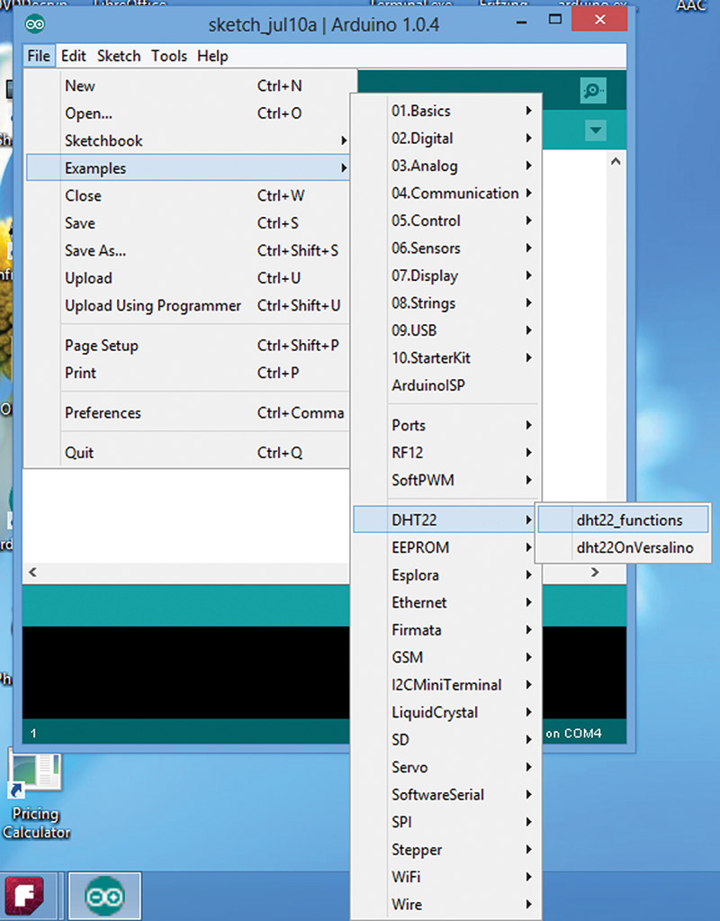
FIGURE 9. Open the DHT22 example.
You can see in the code the various steps required to use the sensor. Add the following to your include list:
#include <dht22.h>
Next, you'll need to create an instance of the class library as follows:
dht22 DHT22;
We have physically attached the DHT22 sensors to pin 11, so you will need to change the following in the example setup function. Change this:
DHT22.attach(2);
to this:
DHT22.attach(11);
Reading the Sensors
We read the sensor as follows:
int chk = DHT22.read();
Reading the sensor returns a value indicating the statues of the read which you may check with the following:
  switch (chk)<br />
  {<br />
    case 0: Serial.println("OK"); break;<br />
    case -1: Serial.println("Checksum error");<br />
    break;<br />
    case -2: Serial.println("Time out error");<br />
    break;<br />
    default: Serial.println("Unknown error");<br />
    break;<br />
  }
You will want to design your own code to respond to these conditions since you only want to use those values from a read that reports "OK."
In the example code, we see several ways to acquire the data that was read, and report it to the serial port:
  Serial.print("Humidity (%): ");<br />
  Serial.println((float)DHT22.humidity, DEC);
  Serial.print("Temperature (°C): ");<br />
  Serial.println((float)DHT22.temperature, DEC);
  Serial.print("Temperature (°F): ");<br />
  Serial.println(DHT22.fahrenheit(), DEC);
  Serial.print("Temperature (°K): ");<br />
  Serial.println(DHT22.kelvin(), DEC);
  Serial.print("Dew Point (°C): ");<br />
  Serial.println(DHT22.dewPoint(), DEC);
  Serial.print("Dew PointFast (°C): ");<br />
  Serial.println(DHT22.dewPointFast(), DEC);
We see the output on the Arduino serial monitor in Figure 10. Note that this runs the serial port at 9600 baud.
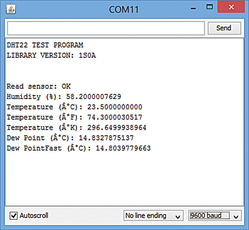
FIGURE 10. DHT22 example.
Two DHT22 Sensors
Adding a second sensor is shown in Figures 11 and 12 in Fritzing breadboard and schematic views. We connect the second sensor to the Arduino pin 10 and make a couple of minor changes in the code. We are now ready to go.
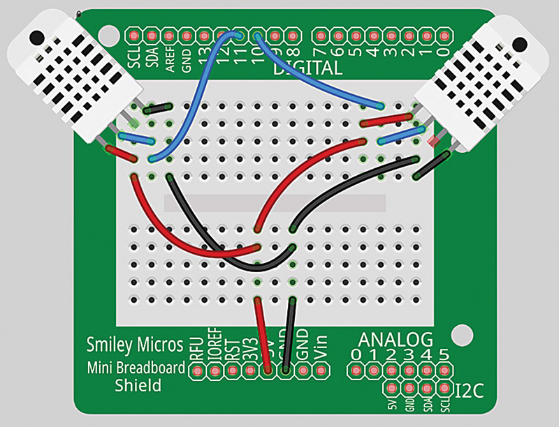
FIGURE 11. Two DHT22s breadboard view.
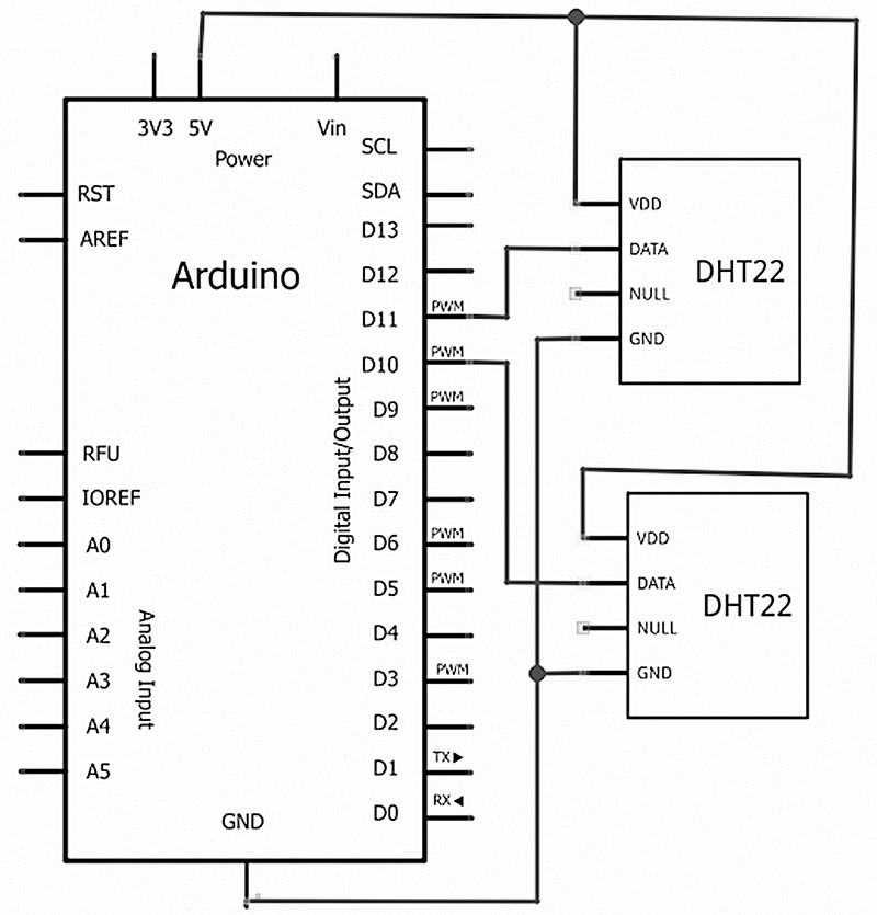
FIGURE 12. Two DHT22s schematic view.
The following source code shows how simple it is to add a sensor to a project when you use a library. In the first example, we created an instance of the dht22 class using dht22 DHT22. For the example that uses two sensors, we simply add two instances of the class with:
dht22 DHT220;<br />
dht22 DHT221;
Next, we copy and paste some code as shown in the listing. We’ll have two sensors working in a matter of minutes:
#include <dht22.h>
dht22 DHT220;<br />
dht22 DHT221;
void setup()<br />
{<br />
  DHT220.attach(10);<br />
  DHT221.attach(11);<br />
 <br />
  Serial.begin(9600);<br />
  Serial.println("DHT22 TEST PROGRAM - two<br />
    sensors ");<br />
  Serial.print("LIBRARY VERSION: ");<br />
  Serial.println(DHT22LIB_VERSION);<br />
}
void loop()<br />
{<br />
  Serial.println("\n");
int chk0 = DHT220.read();
  Serial.print("Read sensor 0: ");<br />
  switch (chk0)<br />
  {<br />
    case 0: Serial.println("Sensor 0 OK");<br />
    break;<br />
    case -1: Serial.println("Sensor 0 Checksum<br />
    error"); break;<br />
    case -2: Serial.println("Sensor 0 Time out<br />
    error"); break;<br />
    default: Serial.println("Sensor 0 Unknown<br />
    error"); break;<br />
  }
  Serial.print("Sensor 0 Humidity (%): ");<br />
  Serial.println((float)DHT220.humidity, DEC);
  Serial.print("Sensor 0 Temperature (°C): ");<br />
  Serial.println((float)DHT220.temperature, DEC);
  Serial.print("Sensor 0 Temperature (°F): ");<br />
  Serial.println(DHT220.fahrenheit(), DEC);
  Serial.print("Sensor 0 Temperature (°K): ");<br />
  Serial.println(DHT220.kelvin(), DEC);
  Serial.print("Sensor 0 Dew Point (°C): ");<br />
  Serial.println(DHT220.dewPoint(), DEC);
  Serial.print("Sensor 0 Dew PointFast (°C): ");<br />
  Serial.println(DHT220.dewPointFast(), DEC);<br />
  Serial.print("Read sensor 0: ");<br />
 <br />
  int chk1 = DHT221.read();<br />
 <br />
  switch (chk1)<br />
  {<br />
    case 0: Serial.println("Sensor 1 OK"); break;<br />
    case -1: Serial.println("Sensor 1 Checksum<br />
    error"); break;<br />
    case -2: Serial.println("Sensor 1 Time out<br />
    error"); break;<br />
    default: Serial.println("Sensor 1 Unknown<br />
    error"); break;<br />
  }
  Serial.print("Sensor 1 Humidity (%): ");<br />
  Serial.println((float)DHT221.humidity, DEC);
  Serial.print("Sensor 1 Temperature (°C): ");<br />
  Serial.println((float)DHT221.temperature, DEC);
  Serial.print("Sensor 1 Temperature (°F): ");<br />
  Serial.println(DHT221.fahrenheit(), DEC);
  Serial.print("Sensor 0 Temperature (°K): ");<br />
  Serial.println(DHT221.kelvin(), DEC);
  Serial.print("Sensor 1 Dew Point (°C): ");<br />
  Serial.println(DHT221.dewPoint(), DEC);
  Serial.print("Sensor 1 Dew PointFast (°C): ");<br />
  Serial.println(DHT221.dewPointFast(), DEC);
  delay(2000);<br />
}
This provides the data to the serial monitor shown in Figure 13.
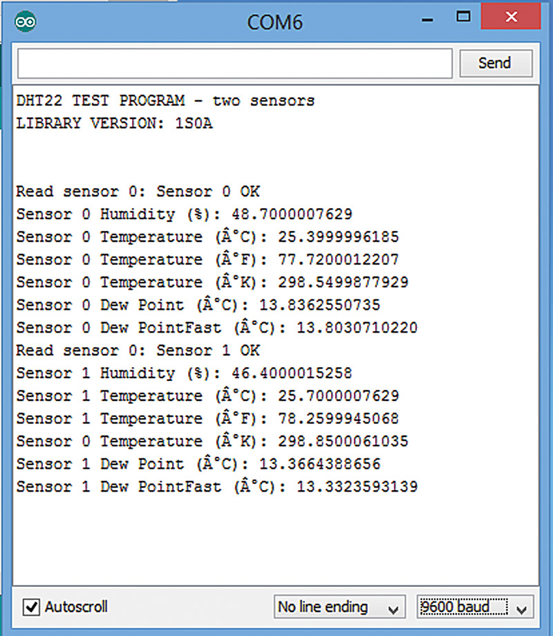
FIGURE 13. DHT22 example with two sensors.
Fresh Air Controller Design
In order to control the fresh air, we need to know the temperature and humidity both inside and outside of the castle. We will look at an algorithm in a moment that lets us set trip points so our attic fan (Figure 14) will come on and draw fresh air through the vent box (refer back to Figures 1 and 2) to provide us with inexpensive cooling or heating as needed.

FIGURE 14. Attic fan.
We hook up the I2C mini terminal part of the handheld prototyper as shown in Figures 15 and 16.
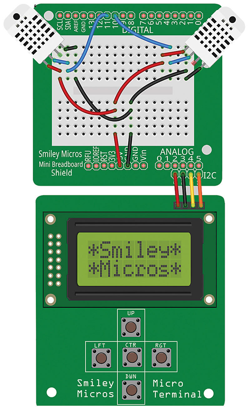
FIGURE 15. Two DHT22s on handheld prototyper.
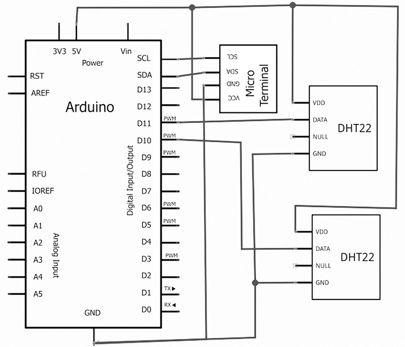
FIGURE 16. Fresh air controller schematic view.
This combines the Arduino proto shield and the I2C mini terminal into the handheld prototyper used in this system. The I2C mini terminal will let the user see the various temperature and humidity parameters on the LCD, and input temperature and humidity setpoints using the keys to select from menu items on the LCD.
The Fresh Air Controller Algorithm
The tasks for the fresh air controller seem fairly simple when you first think about them. If it is too warm indoors and cooler outdoors, you turn on the attic fan. If it is too cold indoors and warmer outdoors, you turn on the attic fan. If the attic fan is on and it starts to rain, you turn off the attic fan.
What you need is for the user to specify what is 'too warm' and 'too cold,' then let the computer logic do the rest. First, you will want to get the user to specify the following values:
setHumidity<br />
setTempLow<br />
setTempHigh
Then, you have the Arduino read the DHT22 for the following values:
humidityOutdoor<br />
tempOutdoor<br />
tempLow
This is the algorithm I came up with for deciding whether to turn the fan on or off, based on the above variables:
  // Run the algorithm<br />
  if(humidityOutdoor >= setHumidity)<br />
  {<br />
    fanState = 0;<br />
  }<br />
  else if( (tempOutdoor > setTempLow) &&<br />
           (tempOutdoor < tempIndoor) &&<br />
           (setTempLow != -1))<br />
  {<br />
    fanState = 1;    <br />
  }<br />
  else if( (tempOutdoor < setTempHigh) &&<br />
           (tempOutdoor > tempIndoor) &&<br />
           (setTempHigh != -1))<br />
  {<br />
    fanState = 1;    <br />
  }<br />
  else<br />
  {<br />
    fanState = 0;    <br />
  }<br />
 <br />
  setFan(fanState);
Please note that in the above code the else if statement should be all on one line in the Arduino code. I split it up here for readability.
First, we check to see if the humidity outdoors is greater than the set humidity (meaning it is raining). If so, we turn the fan off.
Next, we check to see if the temperature outdoors is greater than our low temperature setting AND that the temperature outdoors is less than the indoor temperature, AND that the user has set the low temperature. If all that is true, we turn the fan on.
Then, we check to see if the temperature outdoors is less than our high temperature setting AND that the temperature outdoors is greater than the indoor temperature, AND that the user has set the high temperature. If all that is true, we turn the fan on.
Finally, if none of that is true, we turn the fan off.
Did I say 'fairly simple'? Well it is, but it took me a while to get my head around the logic. Maybe that says something about my head?
Next time, we will see how to complete the design for this handheld prototyper project using the I2C mini terminal to display the fresh air controller data on the LCD and get user feedback from the keys. NV
Downloads
201309-SmileysWorkshop.zip
What’s in the zip?
Workshop 62 Source Code