Smiley's Workshop — AVR C Programming Workshop Series - Part 11
Introduction to Breadboards
I tend to write this stuff with the idea that the reader already knows a bit about electronics. But that isn’t always a valid assumption. For instance, some folks have never used a solderless breadboard. I tried to remember the first time I used one and it just seems like I was born knowing how these things work. I do have vague recollections, however, of using an ohmmeter to figure out that the + and – power busses run horizontally the entire length of the board and that the two grids in the middle of the board have vertical five-position clips. If you have already used one of these things, then skip over this section.
How a Breadboard Works
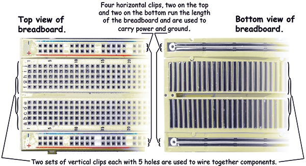
In the good old days, electronics experimenters would build prototypes by nailing components to an actual wooden breadboard and then soldering wire between connection points. Today’s solderless breadboards are made of plastic blocks with holes on 0.1 inch centers that allow you to insert jumper wires (usually 22 AWG) into hidden clips below the holes. The vertical ‘terminal’ blocks let you connect up to five points on each of the 63 double sets of columns. These columns are separated by a 0.4 inch gutter over which you can place an IC or DIP package. You also have four horizontal power bus rows with 50 point clips on each … Oh, who am I kidding? There is no way you can really understand what is going on by reading a written description. It is even hard to take decent photos and have it be clear what I’m talking about. So, I decided to take some photos and get out the crayons and draw some pretty pictures that might just make things clearer.
 |
 |
| FIGURE 1. Breadboard front and back. |
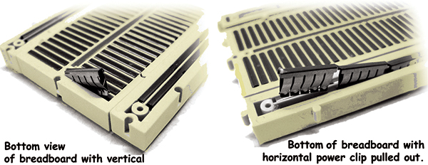
FIGURE 2. Back with five-position vertical and 50-position clips. |
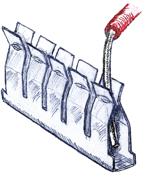
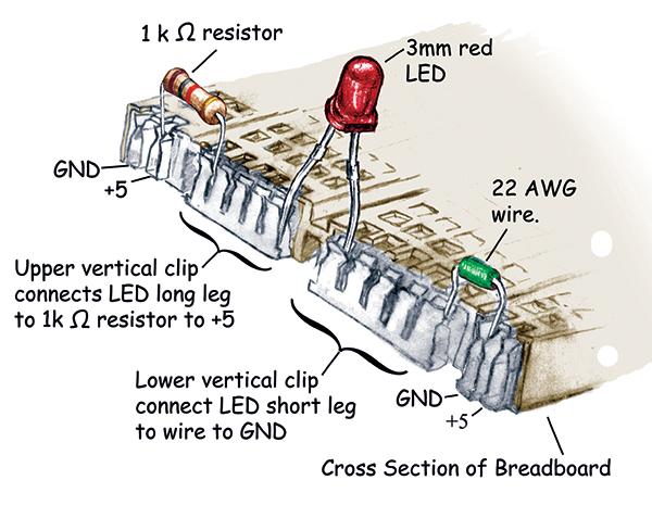
Figure 1 shows the top and bottom of a solderless breadboard (the bottom has the foam tape stripped off to show the connections. Figure 2 shows the clips pulled out. Figure 3 shows how a clip grabs a wire and Figure 4 shows a cutaway drawing with an LED, 1K resistor, and a jumper wire all connected such that if you have +5 volts in the upper + channel and GND in the lower – channel, the LED should light up.
 |
 |
| FIGURE 3. A five-position clip. |
FIGURE 4. Breadboard cross-section with LED, resistor, and wire. |
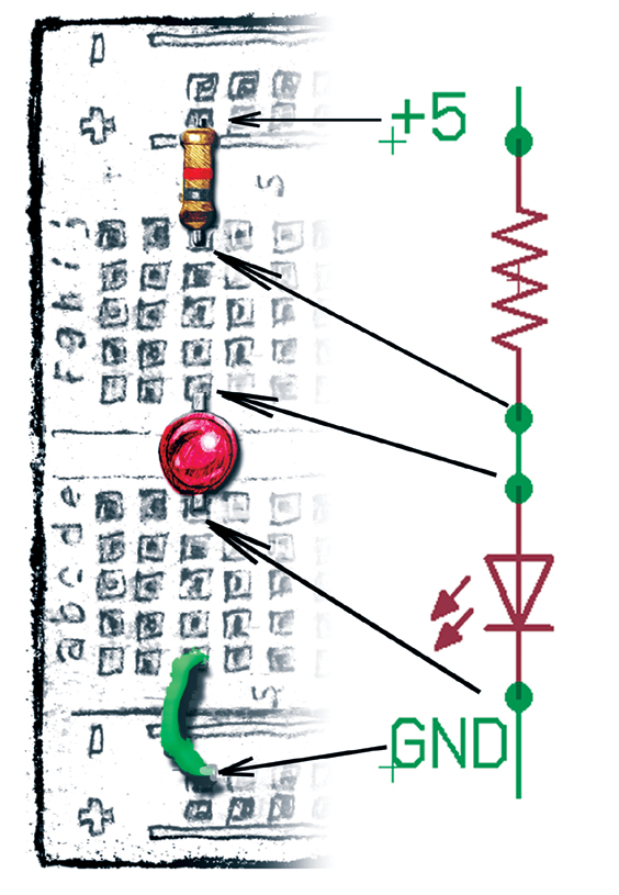 |
| FIGURE 5. Layout drawing and EAGLE Schematic for LED. |
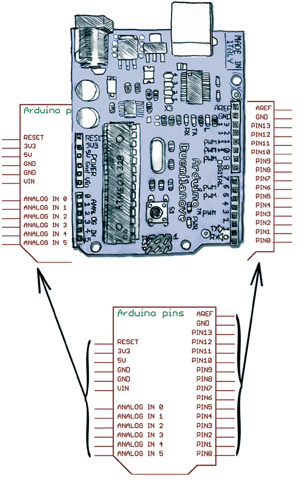 |
| FIGURE 6. Arduino pin-out schematic. |
The clips should handle about one amp at five volts. Breadboards only work for relatively low frequency devices (10 MHz or less) due to high and variable stray capacitance and inductance. Also, the jumpers don’t always maintain a solid connection. I can’t count the times that I’ve had a circuit go weird until I jiggled a few wires and the weirdness went away. However, I’ve gotten microcontrollers to work with 16 MHz external clocks on breadboards, but it isn’t something that you can be totally confident in, so caution is advised. You are trading off reliability for flexibility (and price). You will sometimes see an Arduino design with the ATmega and associated circuits on a breadboard, and there is nothing really wrong with doing that. Just remember, every jumper tie point adds another possible place for a bug, so you have to ask yourself if your time is worth the hassle when you can get the Arduino on a PCB (printed circuit board) pretty cheap.
An Introduction to Schematics
We usually design the schematics for our circuits using software on a PC such as the one I used to generate our schematics: EAGLE (Easily Applicable Graphical Layout Editor). It has a free version for non-commercial use (www.cadsoft.de). EAGLE is hard to use, as are all other schematic/layout programs I’ve used. If you want to use any of these programs, be prepared for a long learning curve. Figure 5 shows a drawing and the schematic for the LED circuit.
Schematic Symbols
Schematic symbols are not standardized, but you often see symbols similar to the ones shown in Figure 5. A resistor is usually shown in America with a ziz-zag, but in Europe they may use a rectangle. The LED symbol is also the symbol for a diode but with a couple of arrows added to show light coming out. We will see other symbols as we build more circuits with the Arduino Projects Kit components.
Using a Solderless Breadboard with the Arduino
Figure 6 shows the schematic symbol for the Arduino pin-out along with the drawing of the Arduino that shows the female headers associated with the pin numbers. These headers have clips in them similar to those on a breadboard, except that there is only one clip per hole.
Schematic and Drawing for the LED and Pushbutton Projects
We saw a photo of this in Smiley’s Workshop #10, but the concepts are repeated here in Figures 7 and 8 for the circuit schematic and drawing.
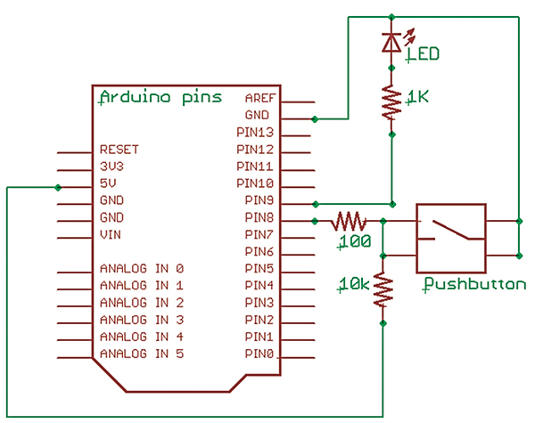 |
FIGURE 7. LED and pushbutton schematic.
|
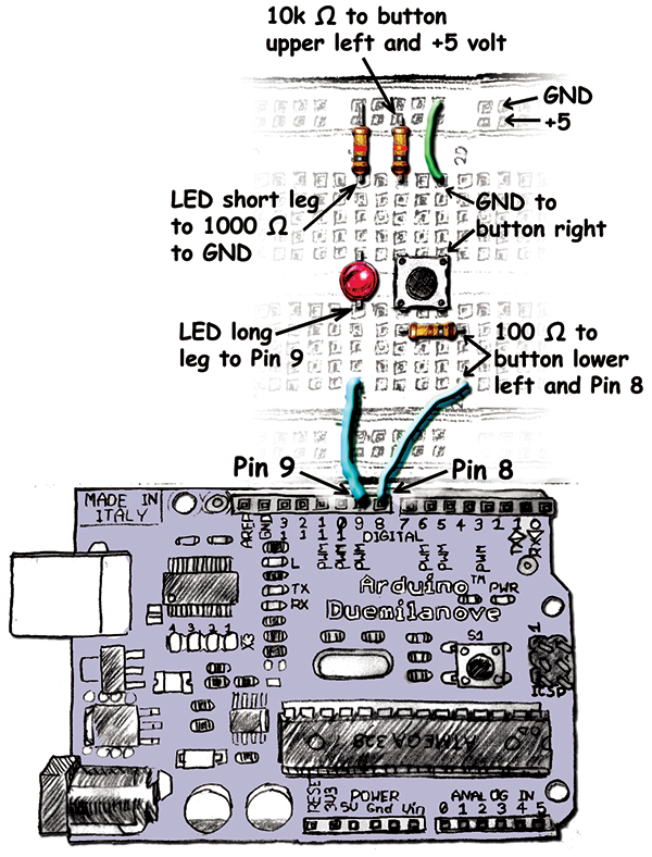 |
| FIGURE 8. LED and pushbutton layout drawing. |
Moving from TAW Serial to ACW Serial
Now that you know more than you ever wanted to know about breadboards, let’s move on to a new software library that will ease our porting software from TAW (The Arduino Way) to ACW (A C Way). In the last Workshop, we learned how to port the code by simply copying all the Arduino source code into our project directory. This time, we will dump all that code into a library — libACW001 — with the major exception that we will be replacing the Arduino serial functions with our own versions. Some of this will be redundant with things we saw last month, but since this can get tricky, a little reinforcement can’t hurt.
Replacing TAW Serial Functions with ACW Equivalents
Much of the Arduino source code (as provided on the Arduino website) will be directly portable to AVRStudio using libACW001.a and the methods described in Workshops 9 and 10. Unfortunately, the serial communication function is not as simple to port, so in this section we will learn to replace them with some similar functions.
The TAW serial functions are written in C++ and we don’t want to go there, so we have replaced each with an equivalent ACW function with a more C friendly name (the dot [‘.’] in the middle of the C++ names gives problems that we don’t need at this point). It is a relatively simple matter to redo these serial functions and we get the added advantage of using the venerable printf() standard C library function. In the old days, the first C program you’d write would use the statement printf(“Hello world!”), and we’ll do the same thing here, just for nostalgia’s sake.
serialBegin(long speed) Replaces Serial.begin(speed)
We use this in the setup() function to set the serial port baud rate. I recommend keeping it set to 57600 which is the same as the bootloader, however, some of the examples run at 9600 baud, so be alert. The various baud rates in different source code cause no end of confusion, so again be alert. If you start receiving junk characters, you probably have the baud rate set wrong.
int serialAvailable() Replaces Serial.available()
This function returns the number of bytes available in the serial port buffer that holds up to 128 bytes.
int serialRead() Replaces Serial.read()
This function returns the next available byte or –1 if the buffer is empty.
serialFlush() Replaces Serial.flush
This function clears the serial buffer.
printf(data) Replaces Serial.print(data) and Serial.println(data)
| TAW |
ACW |
| Serial.begin(speed) |
serialBegin(long speed) |
| int Serial.available() |
int serialAvailable() |
| int Serial.read() |
int serialRead() |
| Serial.flush() |
serialFlush() |
| Serial.print(data) |
printf(data) |
| Serial.println(data) |
printf(data) |
| FIGURE 9. TAW and ACW equivalent serial functions. |
Now we get into some fun. The TAW Serial.print(data) and Serial.println(data) functions will mostly figure out whatever you put in ‘data’ and then send it out. The Serial.println() will add the linefeed character ‘\n’ typically used to tell a terminal that the line has ended. Instead, we will use the standard C library printf() function that is not actually ‘standard’ in our case since it is implemented on an AVR and has some limits that are discussed in the avrlibc manual. We will get into details on this delightful function in later Workshops.
The Venerable “Hello World!” Program
In Kernighan and Ritchie’s classic book The C Programming Language (a.k.a., K&R), the first program you write is:
#include <stdio.h>
main()<br />
{<br />
    printf(“hello, world\n”);<br />
}
The code that makes the printf() function work is stored in the stdio library referenced by stdio.h. Our TAW version of this program is a bit longer than the K&R, while the ACW version is more like the original. Oh, and I changed ‘hello, world\n’ to ‘Hello, World!\n” just because I’m more excitable than K&R. Also, we will blink an LED and repeat the process once a second (much more excitable). We don’t have to do any ALP hardware setup for this since the Arduino board already has pin 13 connected to LED L.
“Hello World!” in TAW
// Hello World! TAW<br />
// Joe Pardue 4-28-2009<br />
// This program outputs<br />
// some text and blinks<br />
// the LED on pin 13<br />
int ledPin = 13;
void setup()<br />
{<br />
  // initialize the UART baud rate<br />
  Serial.begin(57600);
  // sets the digital pin as output<br />
  pinMode(ledPin, OUTPUT);  <br />
}<br />
 <br />
void loop()<br />
{<br />
  // prints Hello World! with ending line break<br />
  Serial.println(“Hello World!”);   <br />
 <br />
  // sets the LED on<br />
  digitalWrite(ledPin, HIGH);    <br />
  delay(1000); // waits for a second<br />
 <br />
  // sets the LED off<br />
  digitalWrite(ledPin, LOW);    <br />
  delay(1000); // waits for a second<br />
}
One last time, let’s show all the details in cookbook style:
- Plug your ALPs into your PC serial port.
- Open the Arduino IDE.
- From the menu, select File\New.
- From the menu, select Tools\Boards\Arduino w/ ATmega328.
- Also in the Tools menus, select Serial Port and make sure the correct one is selected.
- Type the Hello, World! TAW version program into the sketch window. (The code is also available in the Workshop11.zip on the Nuts & Volts website at [url=http://www.nutsvolts.com]http://www.nutsvolts.com[/url]).
- Click the Verify button.
- Click the ‘Upload to I/O Board’ button.
- Watch the Tx and Rx LEDs twiddle.
Using a PC Terminal to See the Results
You can get the Developer’s Terminal or Bray’s Terminal from www.smileymicros.com, but any terminal program should work. We will use my terminal; instructions on how to use it are on my website. Make sure you have chosen the correct terminal and that you have set the baud rate to 57600. You can now watch LED L (pin 13) blink once per second and Figure 10 shows the terminal output.
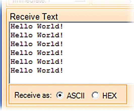 |
| FIGURE 10. Hello World! |
“Hello World!” in ACW
// Hello World! - ACW<br />
// Joe Pardue March 28, 2009<br />
// This program outputs the venerable<br />
// first C program of “Hello, World!!!”,<br />
// then pulses the LED.
#include “libACW001.h”
// LED connected to digital pin 13<br />
int ledPin = 13;
int main(void)<br />
{<br />
    init();<br />
    setup();    <br />
    for (;;)
        loop();<br />
        <br />
    return 0;<br />
}
void setup()<br />
{<br />
  // initialize the UART baud rate<br />
  //Serial.begin(57600);<br />
  serialBegin(57600);
  // sets the digital pin as output<br />
  pinMode(ledPin, OUTPUT);   <br />
}<br />
 <br />
void loop()
{<br />
  // prints Hello World! with ending line break<br />
  //Serial.println(“Hello World!”);<br />
  printf(“Hello World!!!\n”);  <br />
 <br />
  // sets the LED on<br />
  digitalWrite(ledPin, HIGH);    <br />
  delay(1000); // waits for a second<br />
 <br />
  // sets the LED off<br />
  digitalWrite(ledPin, LOW);    <br />
  delay(1000); // waits for a second<br />
}
This time, we will not copy the Arduino files; we will use libACW001 (libACW001.a and libACW001.h are in the Workshop11.zip). Using libraries was discussed in Workshop 4.
Now let’s do it again in ACW cookbook style:
- Create a new directory C:\ArduinoToAVRStudio - Hello World!
- Open AVRStudio and create a new project ‘Hello World’ in C:\ArduinoToAVRStudio-Hello World. Creating AVRStudio projects is described in Workshop 2. Be sure and select the ATmega328p.
- Add the libACW001.a library and libACW001.h header to the AVRStudio project (adding libraries was discussed in Workshop 4.)
- Type in the above ‘Hello, World!’ in ACW source code.
- We use three exclamation points so that we can tell we’ve uploaded this version – the TAW version shows “Hello, World!”; the ACW version shows “Hello, World!!!”
- The AVRStudio project is available in the Workshop11.zip file.
- Click the AVRStudio compile button.
Upload It with AVRDude
- Reread the directions for using AVRDude in Workshop 10 on how to open AVRDude and navigate to the correct directory.
- Open Notepad and type:
cd \ArduinoToAVRStudio – Hello World\default<br />
avrdude -p m328p -c avrisp -P com6 -b 57600 -F -U flash:w:HelloWorld.hex
- Copy and paste the first line into the cmd window and hit enter to point it to the correct directory.
- Copy and paste the second line into the cmd window.
- Push the reset button on the Arduino and at the same time click the enter button so that the cmd window will run AVRDude.
- Open the port in your terminal and you should see ‘Hello World!!!” with all three exclamation points repeating once per second.
Well that should get you started and yield a base for your next weekend project. I am always curious to see what readers construct with the knowledge offered here, so if you build something nifty please drop me a note and share! My website is at www.smileymicros.com and I always welcome your feedback, too. NV
You can find the source code and supplements for this article in Workshop11.zip in the media downloads section on the Nuts & Volts website, at the end of this article, or the Smiley Micros website.
The Arduino Projects Kit
Smiley Micros and Nuts & Volts are selling a special kit:
If you are following along with this seris, you may want to purchase The Arduino Projects Kit which provides components for use with Workshops 9, 10, 11, and other future Workshops. Over time, we will learn simple ways to use these components, and more importantly we will use them to drill down into the deeper concepts of C programming, AVR microcontroller architecture, and embedded systems principles.
With the components in this kit you can:
- Blink eight LEDs (Cylon Eyes).
- Read a pushbutton and eight-bit DIP switch.
- Sense voltage, light, and temperature.
- Make music on a piezo element.
- Sense edges and gray levels.
- Optically isolate voltages.
- Fade an LED with PWM.
- Control motor speed.
- And more …
Our Arduino Uses the ATmega328
Our Arduino Projects Kit has caused a little confusion because it uses the Duemilanove (Italian for 2009) with the ATmega328 (double the memory at the same price) instead of the older ATmega168. These processors have 32 or 16 kilobytes of memory, respectively, so they require a different setting in the Arduino IDE. For our board, open the Tools/Boards menu and select the Arduino w/ ATmega328. Also note that the bootloader runs at 57600 baud, which is faster than the older Arduino bootloader and seems to be confusing some folks on the Arduino forum, so be careful.
One final note:
The USB serial port on the Arduino uses the FTDI FT232R chip that was discussed in detail in the article “The Serial Port is Dead, Long Live the Serial Port’ by yours truly in the June 2008 issue of Nuts & Volts. You can also get the book “Virtual Serial Port Cookbook” (also by yours truly) and an associated projects kit from either Nuts & Volts or Smiley Micros.
Downloads
Smiley’s Workshop 200905 (Workshop11.zip)
