Smiley's Workshop — AVR C Programming Workshop Series - Part 16
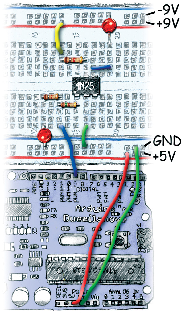 |
| FIGURE 1. Optoisolation Test Layout. |
We are nearing the end of our Workshops that introduce the Arduino Projects Kit. This time, we'll look at several seemingly unrelated topics that we will need to understand before our next article on simple motor speed control. We will learn about external interrupts, using the Arduino IDE Serial Monitor to get real data from the PC serial port to the Arduino board, and optical isolation of voltages.
Using External Interrupts To Detect Edges
One of the things you might want a microcontroller to do is perform a service only when a certain external event occurs. For instance, you could put an IR laser beam across a door and have the microcontroller monitor the beam so that when someone passes through the door breaking the beam, the microcontroller turns on the lights (or drops a bucket of water on the intruder’s head or some such action). If this is the only thing the microcontroller has to do, then it can be dedicated to polling the sensor full time in the loop() function where it would repeatedly run an isItTrippedYet() function that checks the sensor. Polling would drive a person nuts (think of driving kids who are yelling: ‘are we there yet,’ ‘are we there yet,’ ‘are we there yet’…) but fortunately microcontrollers don’t (yet) care what they are doing, so don’t feel sorry for them if you give them a really boring task. Anyway, it’s not like they can retaliate (yet).
Consider the case where a system has lots of other tasks to perform (maybe it’s monitoring dozens of doors and the water levels in all the drop buckets). If it is polling each sensor, then someone could enter the room and be beyond the drop zone before the system even knows they are there. It is very common to conceptually divide up a microcontroller’s work into two groups: one group of routine tasks that can be done any old time and another group of special tasks that must be done immediately when an external event occurs. It is so common, in fact, that most microcontrollers have built-in interrupt peripheral circuitry to accomplish the task.
This circuitry monitors a pin voltage and when a certain condition happens such as ‘was high, now low,’ it generates an interrupt that causes the main program flow to halt, store what it was doing in memory, and then the system runs the function that was assigned to the interrupt. When that function finishes, the system state is restored and the main program runs again.
You mainly deal with interrupts in one of two ways. If a simple task is all that is required and the rest of the program doesn’t need to know about it, then the interrupt service routine can sneak in, handle it, then sneak back out without the main code ever knowing. If, however, a complex task that takes a lot of time away from the main program (yes, it is all relative) needs to be performed, then the interrupt routine should set a flag (change the value of a variable that both it and the main program can see) so that the main program can check that flag as part of the loop() and deal with the consequences of the interrupt when it gets time.
The Arduino library function attachInterrupt(interrupt, function, mode) simplifies the chore of setting up and using an external interrupt. The ‘interrupt’ parameter is either 0 or 1 (for the Arduino digital pin 2 and 3, respectively). The ‘function’ parameter is the name of the function you want to call when the interrupt occurs (the interrupt service routine). The ‘mode’ parameter is one of four constants to tell the interrupt when it should be triggered:
LOW: Trigger when the pin is low.
CHANGE: Trigger when the pin changes value.
RISING: Trigger when the pin rises from low to high.
FALLING: Trigger when the pin falls from high to low.
 |
| FIGURE 2. Edge Detection Schematic. |
Hopefully, you still have your IR detector set up on the breadboard from before (see Workshop 15; Figures 7, 8, and 9). All you need to do in the hardware is move the signal wire from the Arduino Analog pin 0 to the Digital pin 2 as shown in Figure 2, then run the Edge_Detect_Interrupt software. In the former setup, we used the ADC to measure an analog voltage, but this time all we will sense is that the voltage is high enough to represent a digital ON or low enough to represent a digital OFF.
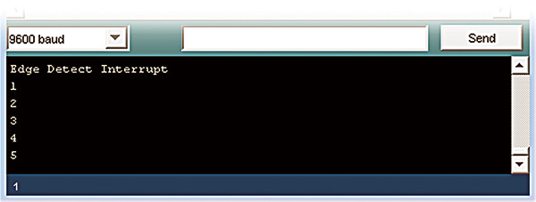 |
| FIGURE 3. Edge Detect Interrupt Counter. |
Run the Edge_Detect_Interrupt software and waggle your finger in front of the sensor to get a count like shown in Figure 3. Next episode, we'll use this concept to detect the passing of black and white stripes on a motor encoder wheel to control the speed of that motor.
Edge Detect Interrupt Software
// Edge_Detect_Interrupt<br />
// Joe Pardue 6/28/09
volatile int count = 0;
void setup()<br />
{<br />
  // setup the serial port<br />
  Serial.begin(9600);<br />
 <br />
  // say hello<br />
  Serial.println(“Edge Detect Interrupt”);<br />
 <br />
  // attach interrupt 0 (pin 2) to the edgeDetect function<br />
  // run function on falling edge interrupt<br />
  attachInterrupt(0,edgeDetect, FALLING);<br />
}
void loop()<br />
{<br />
// do nothing<br />
}
// on each interrupt<br />
// increment and show the count<br />
void edgeDetect()<br />
{<br />
  count++;<br />
  Serial.print(count);<br />
  Serial.println();<br />
}
Getting Real With Serial Input
The Arduino IDE provides a simple Serial Monitor (PC side serial terminal program) and some serial communications functions that allow you communicate with the Arduino board. These functions do a good job in sending serial text from the Arduino to the PC, but (IMHO) not such a hot job of receiving data from the PC. The Serial. available() function tells you when there is a character available on the serial port, and the Serial.read() function will fetch that character for you. However, the Arduino does not provide (that I know of) any Arduino-like simplified way to deal with those characters once you’ve got them.
I contrast this weakness of sorts to a real strength of the C programming language: The C Standard Libraries contain a wealth of functions for dealing with data input over a serial port. I want to emphasize that you can use those C libraries with the Arduino IDE, but that kind-of defeats the purpose of Arduino. I touched on this a bit in an earlier article where I differentiated between TAW (The Arduino Way) and ACW (A C Way), so my approach will be to show what you can do with TAW and save the C libraries for later discussion of ACW. I will present an Arduino program that uses logic that mimics one of those C library functions — atoi() (ascii to integer) — that will allow us to input a sequence of numeric characters using the Arduino Serial Monitor and then convert those characters to an integer data value from 0 to 65535. This will be used in our next installment to set the motor speed.
In Workshop 13, we built a Number_Commander that allowed us to pick a tune to play by entering a numeric character in the Arduino IDE Serial Monitor. While that was cool, it limited us to 10 choices based on input of the characters from 0 to 9. We weren’t actually looking at the numbers 0 to 9, but the ASCII character code that represents those numbers. This is an important distinction because the numeric characters are coded with values that are not the same as what we would normally think of as the value of that character. The character ‘0’ is not coded with a value of 0, but with an ASCII code value of 48. Each subsequent numeric character (1 to 9) is coded as 49 to 57. The ASCII values of 0 to 9 are codes for the communication device (for instance, the ASCII code 7 was used to ring a bell; other low numbered codes were used to do things like advance printer paper or return the print head to the left). There are historic reasons for this coding scheme, but for now just look at an ASCII chart (www.asciitable.com) and accept that when doing serial communications, sending numbers from 0 to 127 actually represents the characters or actions shown in the chart.
The Arduino IDE Serial Monitor allows you to send characters from your PC keyboard, but if you want to send a real number, say 127, then we have to have some way of receiving the characters ‘1’, ‘2,’ and ‘7,’ and some end-of-number character such as ‘!’ so that the software can know that number sequence has ended. We write a program on the Arduino that stores numeric characters until it sees a ‘!’, then converts those characters to the number they represent. For instance, we could send six characters (42356!) and then convert those characters to an integer with a numeric value of 42,356.
Rather than spend a lot of space with further explanations, we’ll just look at the program ASCII_To_Integer. Please be aware that this program can be easily spoofed with bad input, but for learning purposes it will suffice.
If you want a real ‘computer programming’ moment, first think about how you would collect a sequence of numeric characters and convert them to a number. Then, walk through this code with a pencil and piece of paper — especially the ATOI algorithm that extracts the number from the character string. The guys that came up with stuff like this were not only clever, they wrote some amazingly efficient code.
// ASCII_To_Integer 8/1/09 Joe Pardue<br />
// Duplicates (somewhat) the C Standard Library<br />
// function atoi() algorithm using Arduino.<br />
// Note that there is no filtering of the input<br />
// so if you enter something other than an integer<br />
// value from 0! to 65535!, well, good luck.
int myInput = 0;
int myNum[6];<br />
int myCount = 0;<br />
int i = 0;<br />
int n = 0;
void setup()<br />
{<br />
   Serial.begin(9600);<br />
   Serial.println(“ASCII_To_Integer”);  <br />
}
void loop()<br />
{<br />
  // get characters until receiving ‘!’<br />
  while( myInput != ‘!’ ) getNum();<br />
 <br />
  // convert end-of-number character ‘!’ to 0<br />
  myInput = 0;<br />
  myNum[—myCount] = 0;<br />
 <br />
  // convert ASCII string to integer<br />
  ATOI();<br />
 <br />
  // clean up and do it all again<br />
  clearAll();<br />
}
// Put serial characters in a character array<br />
void getNum()<br />
{   <br />
  if(Serial.available())<br />
  {  <br />
     myInput = Serial.read();<br />
     // put the character in the array<br />
     myNum[myCount++] = myInput;  <br />
  }    <br />
}
void ATOI()<br />
{    <br />
  // algorithm from atoi() in C standard library   <br />
  n = 0;<br />
  for(i = 0; myNum[i] >= ‘0’ && myNum[i] <= ‘9’; ++i)<br />
    n = 10 * n + (myNum[i] - ‘0’);
  // show the number<br />
  Serial.print(“You sent: “);<br />
  Serial.println((unsigned int)n,DEC);   <br />
}
void clearAll()<br />
{<br />
  myCount = 0;<br />
  for(i = 0; i < 6; i++)<br />
  {<br />
    myNum[i] = 0;<br />
  }<br />
  Serial.flush();  <br />
}
Optical Isolation of Voltage
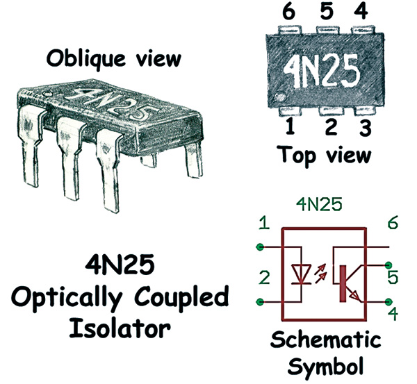 |
| FIGURE 4. 4N25 Optically Coupled Isolator. |
Have you ever had an EKG and noticed that those wires patched to your chest on either side of your heart go to a machine that is plugged directly into a wall socket capable of providing mains voltage? You might even have gotten so excited about the prospect of being electrocuted in the doctor’s office that you were able to make the EKG go wild with all kinds of crazy beeps.
There are many ways to assure that voltages stay separated. The two main ones are electromagnetic isolation with transformers and optical isolation with LED/phototransistor pairs. We will look at the latter as a way to connect a signal between a microcontroller at five volts to a motor at nine volts so that we can prevent the digital equivalent of a coronary in our microcontroller.
Figure 4 provides a drawing and schematic symbol for our optical isolator. You can see that the QRD1114 IR Reflective Object Sensor we looked at in Workshop 15 and the 4N25 Optically Coupled Isolator that we are about to look at have similar schematic symbols (see Figure 5). Note that the main difference is that the QRD1114 shows a dark bar between the LED (emitter) and the phototransistor (detector) subcomponents. These parts are nearly identical from an electronic perspective. The primary difference is the packaging.
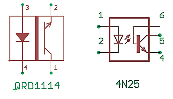 |
FIGURE 5. QRD1114 and 4N25 schematic symbols.
|
The QRD1114 detector is shielded from the emitter and can only ‘see’ the IR if it is reflected back to the device. The 4N25 emitter ‘shines’ directly onto the detector. The QRD1114 detector will pass a current proportional to the reflected IR, thus the signal level is dependent on the external reflective object, while the 4N25 directly responds to the amount of IR coming from the emitter — it can produce a current through pins 5 and 6 directly proportional to a current through pins 1 and 2. If you did something really dumb like connect a wire from a wall socket to pin 1 on the 4N25, you’d fry the LED. However, none of that voltage would pass through to the device connected to pins 4 or 5. This gives us a way to transfer the information in a signal from one circuit to another using light and without having any electrical connection between those circuits.
In next month’s Workshop, we will use this device to isolate a PWM signal at one voltage level, five volts from our Arduino, and scale it to another voltage level (nine volts) for our motor driver.
Optical Isolation Component, Schematic, and Layout
Our hardware demonstration of these concepts uses a five volt signal from the Arduino pin 9 on the emitter side that is converted by the 4N25 to a nine volt signal on the detector side. Wire this up as shown in the schematic in Figure 6, and the drawing in Figure 1.
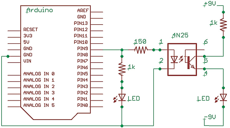 |
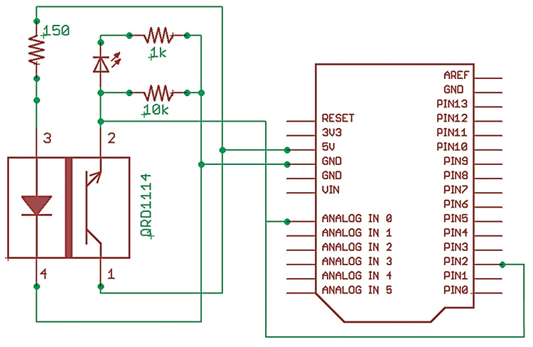
| FIGURE 6. Optoisolator Test Circuit. |
Optical Isolation Source Code
To test this with software, use the ASCII_To_Integer program shown earlier and add just three lines of code. The first two you should add at the top of the file in the variables list are:
int value = 0;  // variable to keep the actual<br />
                // value<br />
int ledpin = 9; // light connected to digital<br />
                // pin 9
Add the third line shown below between the ATOI() and clearAll() functions in the loop() function. The full code is in PWM_Test in this month’s source code download on the Nuts & Volts website.
 // convert ASCII string to integer<br />
  ATOI();<br />
 <br />
  // control the brightness of an LED<br />
  analogWrite(ledpin, n);<br />
     <br />
  // clean up and do<br />
  // it all again<br />
  clearAll();
The integer received from the PC (‘n’) is convertedto a PWM signal on the Arduino pin 9. The PWM will cause the LED brightness to be proportional to the input value (within limits). We will discuss PWM in more detail next month when we use it to control the speed of a DC motor.
The LED on the left is directly driven by the Arduino pin 9 through a 1K ohm resistor and that pin also drives the IR LED in the 4N25 through a 150 ohm resistor. The isolated LED is driven by +9 volts through a 1K ohm resistor to pin 5 of the 4N25, through the phototransistor, out pin 4 to the LED.
And that’s it for loose ends. Next time, we tie this all together and control the speed of a DC motor. NV
You can find the source code and supplements for this article in Workshop16.zip in the downloads section of the Nuts & Volts website and Smiley Micros website.
The Arduino Projects Kit
The Arduino projects kit is a special hardware pack that will help you get hands on experience as you follow along with this series. It provides components for use with Workshops 9, 10, 11, and many future Workshops. Over time, we'll learn simple ways to use these components, and more importantly, use them to drill down into the deeper concepts of C programming, AVR microcontroller architecture, and embedded systems principles.
The Arduino Projects kit is offered through the Nuts & Volts webstore and Smiley Micros website.
Back to top
Downloads
Smileys Workshop 200911 (Workshop16.zip)