C Programming • Hardware • Projects
Recap
Last time, we finished a three part series on serial communications between a PC and an Arduino. We used C# .NET Express to build an Arduino Voltmeter GUI, and we also learned a bit more about the FT232R USB to Serial Port IC that makes Arduino communication with a microcontroller so easy. We now have enough background that we can bust up the Arduino and reconstruct our own version from the pieces.
Why Bust Up A Perfectly Good System?
There are many folks who are ready to move beyond what Arduino does easily. This leads to attempts to twist the Arduino concept all out of shape to make it do things it just wasn’t designed for. I’m seeing arguments developing on various Internet forums between Arduino novices and folks more experienced with microcontrollers who sometimes seem to be yelling at each other across a Grand Canyon sized gap in knowledge. The novice has found that the things the Arduino does well are easy to do, and they don’t seem to understand that many of the things that the Arduino doesn’t do easily can be quite difficult to learn. The experienced folks who probably haven’t messed with the Arduino know that microcontrollers can be difficult to learn about, and don’t seem to understand why anyone would think otherwise. IMHO, the main thing that both sides are missing is that the intended audience for the Arduino was never expected to be or become an expert in microcontrollers.
Consider for a moment the intended audience for the Arduino as stated by Massimo Banzi in his book, Getting Started with Arduino:
“A few years ago, I was given the very interesting challenge: Teach designers the bare minimum in electronics so that they could build interactive prototypes of the objects they were designing.”
He summarizes his philosophy of ‘learning by tinkering’ with a quote from www.exploratorium.edu/tinkering:
“Tinkering is what happens when you try something you don’t quite know how to do, guided by whim, imagination, and curiosity. When you tinker, there are no instructions — but there are also no failures, no right or wrong ways of doing things.”
That last sentence is both the most fun and the most difficult to get beyond. Creativity requires this sort of playfulness, but my experience with microcontrollers — moving beyond what the Arduino does easily — involves about 90% of my time correcting failures. My work habit is to literally fail my way to success. Sorry, but if you want to move beyond being a novice, you have to forget that last sentence — “but there are also no failures, no right or wrong ways of doing things” — because there really are right and wrong ways of doing things, and failures are inherent to working with microcontrollers.
I’m going to draw a line in the sand and say that Arduino is excellent for its intended audience: beginners and for prototyping within the limits of its library. If you want to do things that aren’t built into the Arduino, however, you should migrate to a more capable set of tools. Don’t get me wrong, I wrote the book An Arduino Workshop that, along with the associated projects kit (available from Nuts & Volts), provides an excellent set of tools for getting started. Once you’ve exhausted what can be done easily, then it is time to move on.
Here, of course, comes the emails. Yes, I know that the stuff underlying the Arduino is all open source and can be rewritten to do anything that any other system for AVR microcontrollers can do. But why bother? There are already perfectly good alternative systems, and I’m going to discuss the free one from Atmel (AVRStudio), along with a couple of other open source applications (WinAVR and AVRDude) that have all the AVR and C programming tools you need for more advanced work.
I’ve spent some time with this concept in earlier Workshops, but this month we are going to move to more generic AVR development boards by taking the first step of recreating Arduino hardware on a breadboard. We will then write a test program using AVRStudio/WinAVR. Finally, we will build on the last three Workshops and use C# Express to write AVRUP-V1 — an IDE for uploading code to the AVR.
Breadboarduino
Since my surname is Pardue, which has ardu (French for steep or difficult — hmmm ...) as does arduino, I was tempted to dub this design the Parduino, but humility won me over, so Breadboarduino it is. This hardware system has two main parts: the communications section using the FT232RL and the microcontroller section using an ATmega168.
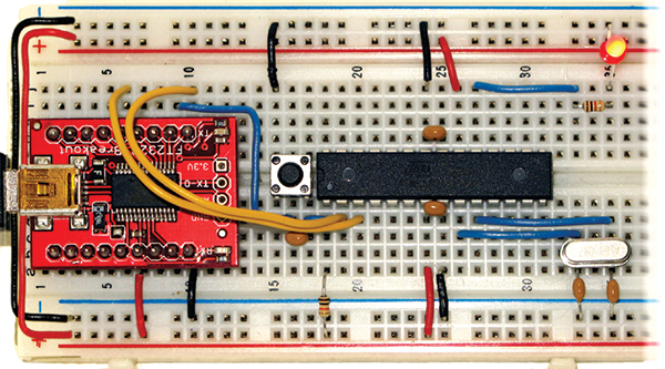 |
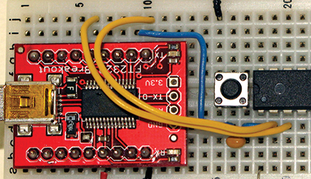
| FIGURE 1. Breadboarduino on a breadboard. |
Using The FTDI FT232R On A Breadboard
In the last few Workshops, we looked at the FTDI FT232R USB Serial Port and learned how to communicate with it using the free C# Express .NET program to build a Simple Terminal and an Arduino Voltmeter. You could get the FT232R portion of the Arduino on a separate PCB, such as the BBUSB (the basis for The Virtual Serial Port Cookbook and projects kit available from Nuts & Volts). You could — but in an unexpected spasm of non-competitive fervor, I’m going to use a competing product in this workshop: the SparkFun FT232R Breakout board. In fact, the full parts list (Table 1) for this project comes from SparkFun.
| Sch. Part |
Description |
SparkFun Part # |
| IC1 |
ATmega168 with bootloader |
DEV-08846 |
| Q1 |
Crystal 16MHz |
COM-00536 |
| S1 |
Mini Push Button |
COM-00097 |
| C1,C2 |
22pF Capacitor |
COM-08571 |
| C3,C4,C5 |
100nF Capacitor |
COM-08375 |
| R1 |
10k Ohm Resistor |
COM-08374 |
| R2,R3,R4 |
1K Ohm Resistor |
COM-08980 |
| L |
Red LED |
COM-00533 |
| |
FT232R Breakout Board |
BOB-00718 |
| |
Break Away Male Headers |
PRT-00116 |
| |
Breadboard |
PRT-09567 |
| |
Hook-up Wire (22AWG) |
PRT-08025 |
| TABLE 1: Breadboarduino Bill of Materials. |
Why am I being so generous? Well, mostly because I don’t want the support headaches. This project is hard to get working! In a later Workshop, I intend to port all these concepts to a PCB that will be the basis for future work and a lot easier to use than a breadboard.
Our first chore will be to put the FT232R board on a breadboard and then test it to make sure the communications side of our system is working. Please note as we progress that things will get increasingly complex and bug-prone, so it will be nice to be able to isolate the sections and test them separately. If you have the final system built and you start seeing flaky stuff (or worse — nothing) on the PC serial monitor side of the cable, then you can pull out the wires, hook in the wire loop, and run the loopback test to make sure the PC and USB sections are working okay.
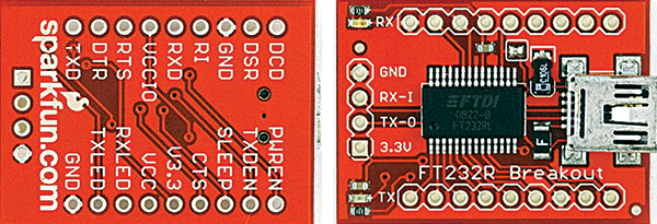 |
| FIGURE 2. SparkFun FT232R breakout. |
SparkFun FTDI Breakout
You will need to break off two nine-pin sections of the break-away headers and solder them to the board (long legs down) so that you can plug it into a breadboard. You may notice one tiny problem: The pin labels are on the bottom of the board so when you have it plugged into a breadboard as shown in Figure 3, you can’t see which pin goes where. I’ve sort of solved this by producing a Word document with the table shown in Figure 3 that when cut out and folded like a tent, has the pins labeled. You can get the Word document in the Workshop21.zip.
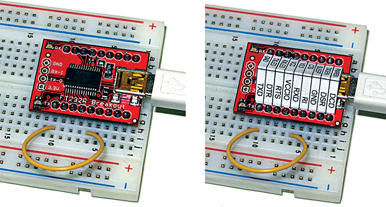 |
| FIGURE 3. Loopback test with hat. |
The Loopback Test
After you’ve got your loopback hardware completed, you can test this with the Simple Terminal we built in Workshops 18 and 19.
 |
FIGURE 4. FT232R breakout schematic.
|
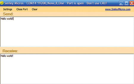 |
FIGURE 5. Loopback test in the Simple Terminal.
|
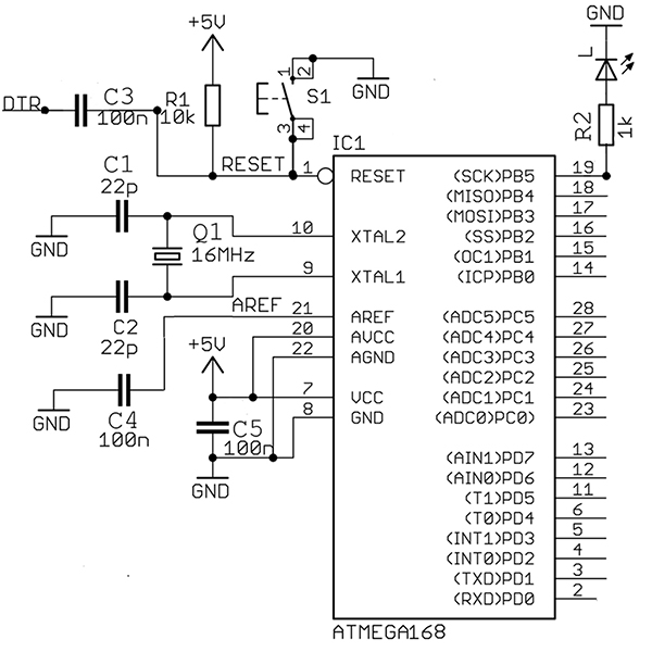 |
| FIGURE 6. Breadboarduino schematic. |
Building The Breadboarduino
 |
| FIGURE 7. Automatic and manual reset. |
We will simplify our lives in this section by leaving off the Arduino power supply section and using only the power from the USB port. Theoretically, we can take 500 mA from the USB, but there are caveats that cause me to advise using less than 100 mA. This should be enough to do a Cylon Eyes type project, but probably not enough to run motors.
Not all the parts in the figures are exactly like those from SparkFun. I used several color wires and a longer breadboard. Also, if SparkFun has an ATmega328 with a bootloader, get that instead of the ATmega168 and translate where appropriate.
When I built the section shown in Figure 7, I had the upper black wire two spaces to the right and nothing worked. Duh, running /RESET to ground tends to create that symptom. I moved it to the position shown and everything worked.
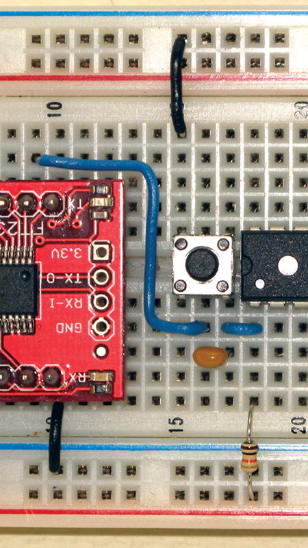
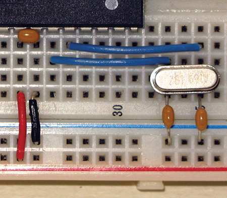
In Figure 8, the serial communication wires are in yellow. You may need to put the paper tent label on the FT232R breakout board to see where the TxD and RxD go. REMEMBER: The TxD on the FT232R board goes to the RxD on the ATmega (pin 2), while the RxD on the FT232R goes to the TxD on the ATmega (pin 3). This confuses a lot of folks, but think about it for a moment. The data being transmitted from the PC through to the FT232R is being received by the ATmega. The data being received by the PC through the FT232R is being transmitted by the ATmega. Figure 9 provides an enlargement of the section containing the crystal and the power.
 |
 |
| FIGURE 8. TxD and RxD. |
FIGURE 9. Crystal and power. |
Hello World Program For The Breadboarduino
It is not my intent to scare anyone with a code listing, though I fear that those familiar with the Arduino but not yet comfortable with regular C programming will feel like they’ve been backing down a dark hallway in an old house shining a flashlight in their own eyes when BUMP — they get a look at this code. Relax guys, this isn’t a slasher film, and we will — over time — learn what all this means. For now, just type it into the AVRStudio editor [or get the source from Workshop21.zip].
/* **********************************************<br />
Breadboarduino_Hello_World Joe Pardue February 10, 2010<br />
********************************************** */<br />
#include <stdio.h><br />
#include <avr/io.h>
#define FOSC 16000000<br />
#define BAUD 57600<br />
#define MYUBRR FOSC/16/BAUD-1
uint8_t receiveByte( void );<br />
void init();
// From example in avrlibc manual<br />
static int uart_putchar(char c, FILE *stream);<br />
static FILE mystdout = \<br />
FDEV_SETUP_STREAM(uart_putchar, NULL, _FDEV_SETUP_WRITE);
int main(void)<br />
{<br />
    uint8_t b;<br />
    uint8_t count = 0;
init();
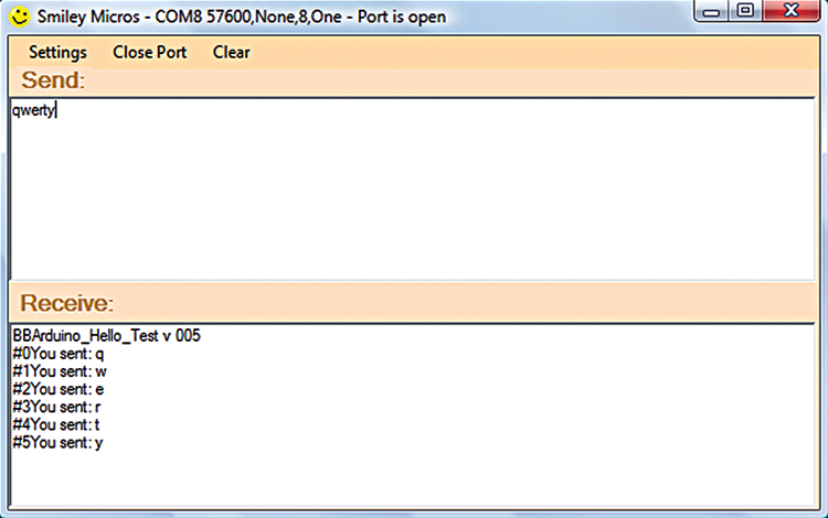
printf(“BBArduino_Hello_Test v 005\n”);
    while(1)<br />
    {<br />
b = receiveByte();
      printf(“#%d”,count++);<br />
    printf(“You sent: %c\n”,b);<br />
    }
    return 0;<br />
}
static int uart_putchar(char c, FILE *stream)<br />
{<br />
    if (c == ‘\n’) uart_putchar<br />
    (‘\r’, stream);
    // wait for UDR to be clear<br />
    loop_until_bit_is_set(UCSR0A, UDRE0);<br />
    UDR0 = c;    //send the character<br />
    return 0;<br />
}
void init()<br />
{<br />
    //USART Baud rate: 57600
    UBRR0H = (MYUBRR) >> 8;<br />
    UBRR0L = MYUBRR;<br />
    UCSR0B = (1<<RXEN0)|(1<<TXEN0);
    //set the output stream<br />
    stdout = &mystdout;    <br />
}
uint8_t receiveByte( void )<br />
{<br />
    // Wait for data to be received<br />
    while ( !(UCSR0A & (1<<RXC0)) );    <br />
    // Get and return received data from buffer<br />
    return UDR0;<br />
}
Compiling In AVRStudio
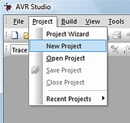 |
FIGURE 10. Select New Project.
|
I presume you’ve downloaded and installed the latest and greatest AVRStudio and WinAVR. If not, get them at:
www.atmel.com/dyn/products/tools_card.asp?tool_id=2725
http://winavr.sourceforge.net/download.html
Open AVRStudio and click on the Project\New Project menu item as shown in Figure 10. A window will open as shown in Figure 11. Highlight ‘AVR GCC,’ browse to a location for your file, and name the file under ‘Project name.’ Then click ‘Next>>.’
 |
 |
| FIGURE 11. Project type and file name. |
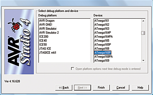
FIGURE 12. Platform and device. |
In the next window (shown in Figure 12, select the ‘Debug platform’ AVR Simulator and the Device ‘ATmega168P (unless you got the 328); finally, click finish. You can now input the program in the edit window as shown in Figure 13.
 |
 |
| FIGURE 13. Input program in edit window. |
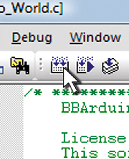
FIGURE 14. Build active configuration. |
Click on the ‘Build Active Configuration’ button as shown in Figure 14; if all goes well, you’ll get the ‘Build succeeded with 0 Warnings…’ message.
AVRUP V1 — An AVR Program Uploader
The one thing I might miss about the Arduino is how easy it uploads programs to the micro. AVRStudio has AVRProg for uploading, but that thing is so bad that even Atmel no longer supports it. When it works, it is fine, but when there is a problem, it doesn’t give many hints as to what might be wrong. The Arduino uploader function is also great when it works, but when there is a problem — it can be down right scary. The little black box at the bottom of the IDE fills with bright red text listing a bunch of cryptic complaints that the novice has no chance of understanding. [I’ll assert at this point that if one knows about the underlying avrdude error messages, one is not a novice.] I imagine most novices peek at those bloody looking messages and freak out a bit. One of the goals of AVRUP is to run avrdude in the verbose mode and list everything it has to say in nice black text on a white background, making it easier to get the avrdude manual and figure out what the problem is. [The avrdude manual is in the WinAVR doc directory.]
Back in Workshop 10, I showed how to use avrdude in the Windows command line but personally, I find it can be a PITA to use avrdude casually in Windows because it requires a list of parameters that are daunting to figure out, type in, and remember the next time you use it. None of these are faults in avrdude — a great program — but for me a more automated process helps a lot (get it right once, then forget how you did it). So, I decided to write a helper program in C#. (Aren’t you glad you paid attention to the last three Workshops?)
You can get AVRUP V1 as an application and the full source code in Workshop17.zip. I’m not going to discuss that code further here because all the basics were covered in the last three Workshops.
Avrdude On The PC Talks To A Bootloader On The AVR IC
We usually think of a microcontroller as a general-purpose device that has an application program on it defining specifically what it does. An AVR with one application might control the fuel/air mixture in your car’s engine. An identical AVR — but with a different application — might control your microwave oven. There are many ways to get an application program loaded onto a microcontroller. One that I like a lot is a bootloader. For this, the AVR memory is divided into two sections: one to hold the bootloader software, and another to hold the application software. We will leave the problem of how to get the bootloader into the AVR for a later article, but this month we’ll purchase an AVR with the bootloader already on it.
The bootloader on the Arduino is a standard AVR bootloader that starts running when the AVR comes out of reset. It spends a few seconds using the USART serial port to see if something is out there wanting to upload a new application and if not, it gives over control to the resident application program. If something (an uploader) is on the port and knows how to speak bootloader talk, then the bootloader and the uploader collude to take the application program from the PC and put it in the AVR application memory (overwriting the previous application). The bootloader’s final act is to set the AVR to run the application.
Uploading With AVRUP V1
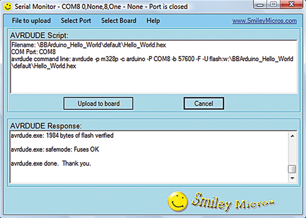
Open AVRUP V1, click on the ‘File to upload’ menu item, and select the Hello_World.hex file from whereever you stored it. Next, click the ‘Select Port’ item and select the COM port your Breadboarduino is using (this item should be familiar from the last three Workshops). Next, click on the ‘Select Board’ item and select the ‘ATmega168.xml’ file. The ‘AVRDude Script’ window should look like the one in Figure 15 (except for the m328p which should be m168p). Now, click ‘Upload to Board’ and watch your Breadboarduino LED flash indicating reset, and note that the red and green LEDs on the SparkFun board twiddle around as avrdude communicates with the bootloader. The ‘AVRDUDE Response’ textbox fills with lots of information and is followed by ‘avrdude.exe done. Thank you.’
 |
 |
| FIGURE 15. AVRUP VI. |
FIGURE 16. Hello test. |
Finally, fire up Simple Terminal and test the board as shown in Figure 16.
No Seriously ...
What are the chances that you are going to build all this and have it go as smoothly as indicated by this Workshop? Remember what I said about failing your way to success? Well, all I can say is that I messed up multiple times at every step, but did eventually get it all working. You have all the source materials and should be able to duplicate my success. Next time, we are going to take all we’ve learned of late and build an even more capable system to support our future learning about the AVR architecture and C programming. NV
Downloads
Smileys Workshop 2010-04 (Workshop21.zip)