Recap
Last time, we continued our AVR Memory series and discussed reading the program memory in Flash. We learned how to store constants in Flash to avoid unnecessarily cluttering SRAM and we learned how to read data from Flash. Now we're ready to learn how to write to Flash using C functions from avrlibc. This will be the basis for our final article in the memory series (next time) where we apply what we’ve learned to building a bootloader.
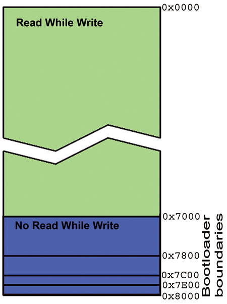
FIGURE 1. ATmega644 Flash memory.
My Big Fat BSOD
FYI, I got a Vista BSOD (Blue Screen Of Death) while testing this code. Figure 2 shows the message I got after I rebooted. You’ll note that it gave me the option to either cancel or check later, but no option to check now. Ah, Vista ... you gotta love it.
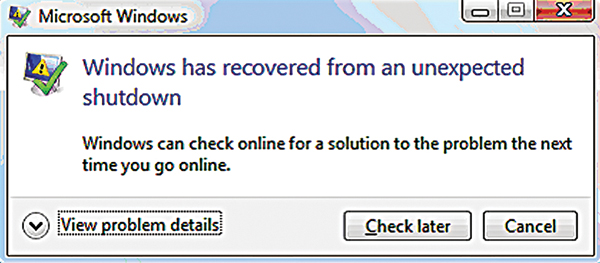
FIGURE 2. After the BSOD.
I think my big fat BSOD was because an error in the AVR code caused the serial port to be blasted with data while I was using Bray’s Terminal. Well, at least Bray’s was being blasted with data when I got the BSOD. Everything recovered okay and I fixed the code to be blast free. But you never know ...
Writing To Flash
Flash is easy to read, but hard to write.
In previous articles, we’ve seen that the AVR uses three main types of memory: SRAM, EEPROM, and Flash. We learned that SRAM is the most expensive and only used to store data that changes a lot when the CPU is running; that EEPROM is cheaper and is useful for storing byte-sized constants that change occassionally; and finally, that Flash is cheapest of all and is used to store the program code that rarely changes. Flash and EEPROM use similar technology, but EEPROM can be programmed in individual bytes while Flash is programmed in pages. This reduces the circuitry necessary to program Flash, thus making it cheaper. Flash page size varies depending on the particular AVR device.
Flash is addressed by words, not bytes.
One additional noteworthy feature of Flash versus the other memory is that Flash stores data as 16-bit words, meaning that eight-bit byte data is stored in either the high or low part of a word. For me, this creates a conceptual problem because for the AVR — which is an eight-bit system — we think in terms of bytes. So, why is the memory now considered in words? Well, that is because the Flash memory itself is a peripheral (something outside the CPU) that is erased and written to in pages with word-sized boundaries. I find this confusing and suggest that you just do what I do: Try to remember that when the CPU is reading Flash memory, it is doing it in bytes but that when we are talking about actually erasing or writing to the Flash memory, we are doing that in page-sized chunks that are defined in words.
The Arduino (ATmega328p) and the Butterfly (ATmega169) both have pages of 64 words, while the BeAVR40 (ATmega644p) has 128 word pages. Later when we look at boot section addresses, we might notice things like the ATmega644 boot section that begins at 0x7E00, and if we translate that into decimal we might wonder why the bootsection begins at 32256 when we are using a 65535 (64K bytes) memory. The answer is, of course, that we are actually using a 32K word memory and that the boot section is a word address that corresponds to a byte address of 0xFC00 (64512). It can sometimes be confusing whether you are talking about words or bytes in Flash memory, so pay attention.
How Flash is written.
When we write to Flash on the ATmega644, we first fill a SRAM temporary buffer page with 128 words and then let the Flash circuitry write that whole page to Flash. Even if all we wanted to do in Flash is change a single byte, we have to find what page it is in, copy that whole page of 256 bytes (128 words) to SRAM, and then wait while the SRAM gets written to Flash. As we’ve said before, you can write to Flash but you can also wear it out. So, it isn’t something we want to do a lot. We don’t use it to store frequently changing data, but only to store occasionally changing things like the program code itself. Most microcontrollers only have the program written once and they run it to the end of time. We, of course, are learning about these things, so will write the program code many times to both learn new stuff and to correct the inevitable mistakes we make.
Would you change code while it is running? (Hint: NO!)
A computer loads a sequence of instructions from the program memory and performs operations based on that code. We assume there is some logic to the design of that sequence so that, for instance, if we add two numbers then the result is used for some later instruction in the sequence. But what if we could change the program sequence while it is running? We might get lucky and change a section that won’t be used for a while, but then we might get unlucky and change something that is being used right now. Since that is a risk we don’t want to take, we try to assure that the computer won’t be running code that is in the process of being changed. We don’t want to be reading code while writing to it.
As we introduced in Workshop 22, bootloaders write code to program memory. A bootloader is a module of code that writes code while it is running. You see the potential problem here? You’ve got to have a mechanism that prevents you from writing over code you are running. The AVR has special features that make it easier to safely use bootloaders. One of these is to divide the program memory into two sections: a RWW (Read While Write) and NRWW (No Read While Write) section as shown in Figure 1. This allows us to designate a section of memory that will not allow the CPU to read the program memory while writing to program memory. This assures that code running in the NRWW section won’t overwrite itself. [We use an external ISP programmer to write to the NRWW section which is done without the CPU running.] As you can see in Figure 1, the NRWW section is divided into subsections that mark boundries that you can set for your bootloader. These boundaries are set by fuses that tell the AVR to run code beginning at that indicated address when coming out of reset. In our Flash writing example [see Figure 3], we will use the smallest section available that begins at address 0x7E00 [remember that Flash is measured in words]. This means we have 512 words or 1,024 bytes to store in our bootloader. We will learn how to use this to write data to Flash and next month we will apply what we learn to developing a bootloader.
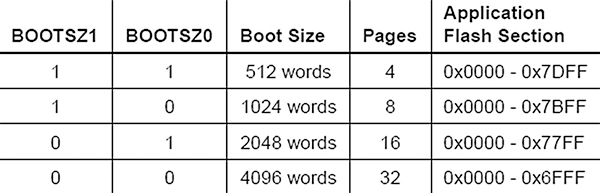
FIGURE 3. ATmega644 boot size.
When an NRWW section is being written to, the CPU is stopped to make sure it doesn’t try to run a page of code that is in the midst of being changed. We can continue to execute code in the NRWW section while parts of that section are being written to. This allows our application to continue to run critical code while the rest of the program is being updated. This is an advanced topic that we won’t look at further here.
Preventing Flash Corruption.
You should never initiate a Flash write if there is a chance that you’ll run out of power in the midst of it. This could corrupt that page of Flash and when the power is restored, the program may be corrupted. One way to deal with this is to enable the internal BOD (Brown-Out Detector) to prevent the CPU from operating below a certain voltage. We will do this by setting the BODLEVEL fuse to “Brown-out detection at VCC=2.7V.” We’ll see how to set fuses in a few minutes.
Flash Read/Write Functions From AVRLIBC
Writing to Flash requires using the assembly instruction SPM, but we are writing our code in C so we will use some C library functions and let them handle the low level stuff. Avrlibc is included in your WinAVR installation. You can find the manual for it under the WinAVR directory doc\avrlibc\avr-libc-user-manual.pdf. This library provides a lot of useful tools and we will use some of the bootloader support utilities available to us by including <avr/boot.h> in our program. We use the following functions:
boot_page_erase(address); Determines the Flash page that contains the ‘address’ and erases that page.
boot_spm_busy_wait(); Checks to see if the SPM instruction is busy. This sits around blocking further action until the Flash has finished writing.
boot_page_fill(address,tempWord); Used to fill the temporary page buffer. It is odd in that it uses a byte address but writes a word, so you have to load the high and low bytes of the tempWord and then add two to the address to load the next word. The algorithm is shown in the blockFlashLoad function we’ll discuss in a moment .
boot_page_write(address); Writes the temporary page buffer to the Flash page containing the address.
boot_rww_enable(); Enables the read while write section after you are finished with your writing.
We will demonstrate how to use these function in a program that lets us write data to Flash.
SmileyFlashTest.c
Our demonstration program — SmileyFlashTest.c [available in Workshop26.zip in the downloads section] is built on top of last month’s pgmtest.c program and contains some communication and logic code that were discussed in that workshop. For this discussion, we will focus on using the avrlibc boot functions to write Flash data.
We will test these concepts by letting the user write 16 bytes to address 0x2000. There are two versions of this write: one will write the sequence 0 to 15 and the other will write the sequence 15 to 0. We write the first sequence by using Bray’s Terminal to send ‘w’ and the second sequence by sending ‘W.’ We test that the write has actually occurred by reading 16 bytes from address 0x2000 by sending ‘r.’
The action we are interested in occurs in the blockFlashLoad function that follows:
void blockFlashLoad(uint16_t size)<br />
{<br />
    // address is global and set elsewhere<br />
    uint16_t tempAddress = address;<br />
    uint16_t i,tempWord;
    // Perform page erase<br />
    boot_page_erase(address);
    // Wait until the memory is erased<br />
    boot_spm_busy_wait();        .
    // fill the flash page buffer with the data<br />
    for(i = 0; i < size; i+=2)<br />
    {<br />
    // load the little end byte from the word<br />
    tempWord = pageBuffer[i];
    // load the big end byte<br />
    tempWord += (pageBuffer[i+1] << 8);<br />
        <br />
    // put the word into the page butter<br />
      boot_page_fill(address,tempWord);;<br />
        <br />
    // incrememnt the word address                        <br />
      address = address + 2;<br />
    }<br />
    <br />
    // write the page to flash
boot_page_write(tempAddress);
    // wait until finished writing<br />
    boot_spm_busy_wait();<br />
    <br />
    // Re-enable the RWW section<br />
    boot_rww_enable();
    // send ! to shown you are done<br />
    sendByte(‘!’);<br />
}
We see from this that we first erase the Flash page, wait until the erase is finished, load our data into a page buffer, write that page buffer, wait until the write is finished, re-enable the read while write section, then finally send an ‘!’ because we are amazed that this actually worked.
One source for multiple AVRs.
At this point, we are going to go off on a tangent unrelated to memory but important for our current and future Workshops, and that is the concept of creating one source code module that can be easily compiled for several different AVRs. It is common when writing software to want to run it on different devices. For instance, I might want to provide the reader with the opportunity to run the test code on an AVR Butterfly [ATmega169], or an Arduino board [ATmega328], or the BeAVR40 [ATmega644 discussed in Smiley’s Workshop 22: Busy as a BeAVR]. I could produce three different source code files for this and that would probably be the easiest for the reader to use. But for me, it would be a lot harder since most of the code would be common for all three sets and I’d have to make sure that I made every little change or error correction to all three files.
Many implementations of C use a preprocessor that is run before the compilation. We can include macros using the #define statement that tells the compiler to substitute one set of text for another. We can also have conditional inclusion using the #if preprocessor statements (remember this isn’t the C program ‘#’ or ‘if’ — it is a preprocessor ‘#if’). We will use the #define and #if preprocessor statements to generate code that can be made to compile for one of our three systems, depending on which system is defined. Near the top of the SmileyFlashTest.h header file, you will see:
//#define Butterfly // ATmega169<br />
//#define Arduino // ATmega328<br />
#define BeAVR40 // ATmega644
You can get the compiler to generate code for your particular system by removing the // comment directive from the #define while making sure all the remaining defines have // in front of them. In the case above, the ATmega644 is selected. Later in the code, we will use the preprocessor #if directive to select the code for the indicated device as we see in the following:
// Constants used to calculate the register<br />
// settings for each device baudrate<br />
#if defined(Butterfly)<br />
  #include <avr/interrupt.h><br />
  #define F_CPU 8000000<br />
  #define BAUD 19200
#elif (defined(Arduino) || defined(BeAVR40))<br />
  #define F_CPU 16000000L<br />
  #define BAUD 57600<br />
#else<br />
  #error “F_CPU and BAUD undefined”<br />
#endif
These #if conditions set the bootloader baud rate. If none of the devices are defined, it causes the compiler to generate the following error:
../SmileyFlashTest.h:105:3: error: #error “F_CPU and BAUD undefined”
The F_CPU and BAUD are used to calculate the baudrate in the USARTInit() function in the source code. This function also uses the #if #elif preprocessor directives to select and set other device-specific USART registers.
IMHO you have to be careful how you use the preprocessor or you can get nearly unreadable source code. I have at times had to go through other people’s code and delete all the conditional statements that weren’t relevant to the device I was using just so I could follow the logic of their code. The Arduino bootloader [http://code.google.com/p/arduino/source/browse/#svn/trunk/hardware/bootloaders] is a bit like this IMHO, though not nearly as bad as some I’ve come across. Since I plan to keep future Workshops to the three devices listed, we can hope that the code won’t get too cluttered.
Using AVRStudio To Compile And Load FlashWriter
AVRStudio now has features that allow you to compile programs without having to mess with a Makefile. We will set some Project Options and will make sure that the correct fuses are set in our AVR Programmer.
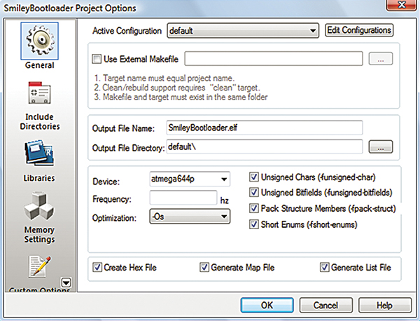
FIGURE 4. Project Options - General.
Settings for Project Options.
In the AVRStudio Project menu, open Configuration Options. In Figure 4, we see the General page set for the ATmega644p used in the BeAVR40.
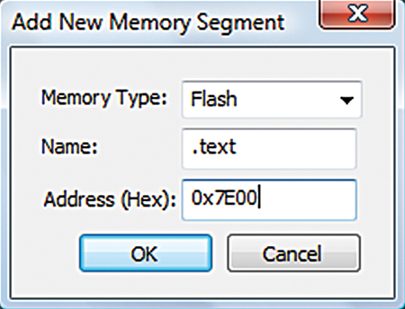
FIGURE 5. Add New Memory Segment.
Setting the Memory Settings.
Open the Memory Settings panel and click on the Add button. In the Add New Memory Segment dialog shown in Figure 5, select Flash, type in the name “.text” making sure to include the preceding dot in .text, then set the address to 0x7E00 (the beginning of our bootloader memory segment). The results should be as shown in Figure 6.
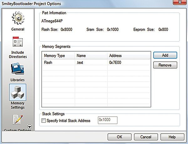
FIGURE 6. Project Options - Memory.
Settings for fuses.
We want this code to write to Flash so it must reside in the bootloader section. We want to tell the AVR that it should run this code when the device comes out of reset, and we should tell it where the code is located.
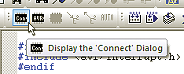
FIGURE 7. Display Connect Dialog.
Click the Display the ‘Connect Dialog’ button as shown in Figure 7.
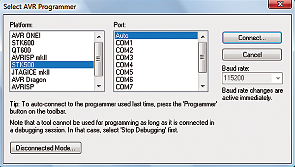
FIGURE 8. Select AVR Programmer.
This will open the dialog in Figure 8 on which you click connect. [Note that in Workshop 22, we used the AVRDragon rather than the STK500 for the programmer, but the details shown here are the same.]
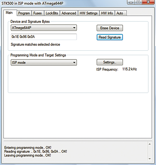
FIGURE 9. STK500 Main tab.
The ISP programmer window will open as shown in Figure 9, and in the Main tab you can click on the ‘Read Signature’ to verify that you are communicating with the ATmega644p.
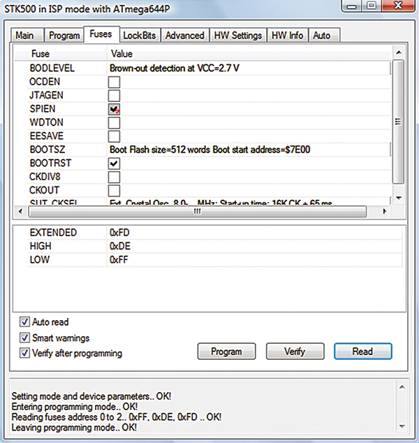
FIGURE 10. STK500 Fuses tab.
Next, click the Fuses Tab and change the settings to those shown in Figure 10. Then, click the Program button to set the fuses. We mentioned earlier that we’d set a fuse to help prevent writing when we are running out of power. We set the BODLEVEL fuse to “Brown-out detection at VCC=2.7V” as shown.
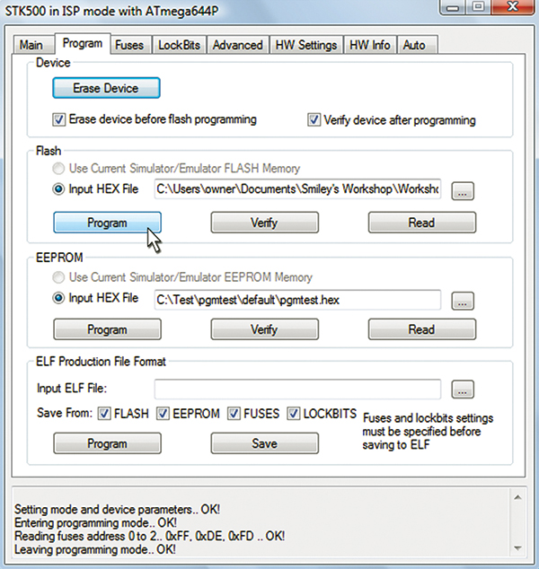
FIGURE 11. Upload the bootloader.
Finally, click the Program Tab shown in Figure 11, then you ‘Browse’ to select the directory containing the SmileyFlashTest.hex file. Click the ‘Program’ button and your bootloader should upload to your ATmega644.
Using SmileyFlashWriter
This is a simple program with three commands to read and write the sequence discussed above: ‘r’ to read the bytes; ‘w’ to write them in increasing order; and ‘W’ to write them to 0. When you first open the program, type in ‘r’ and you’ll see 16 zeros; type ‘w’ then ‘r’ and you’ll see the hex bytes 00 to 0F. Then, try ‘W’ and ‘r’ and you’ll see 16 zeros. The output is shown in Bray’s Terminal in Figure 15. But hey, it does demonstrate that we are writing to Flash. Fun, huh!?
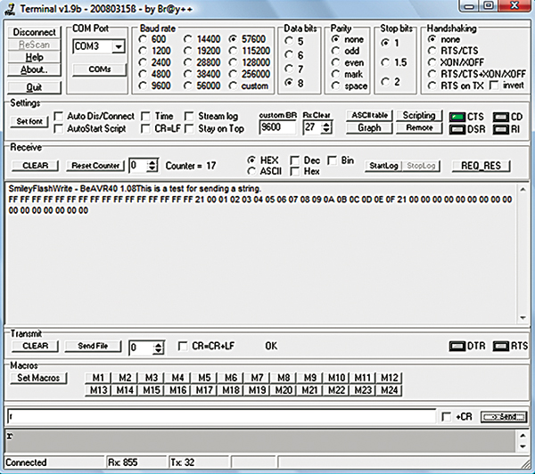
FIGURE 15. Output shown in Bray’s Terminal.
Reality Check – Did it REALLY write the data?
Yeah, we used ‘r’ to read the data we wrote to Flash, but we can add a second test to see if it really happened and read the whole Flash using AVRStudio. This is useful since it gives us a tool to inspect the entire Flash memory, which can come in handy in some debugging situations.
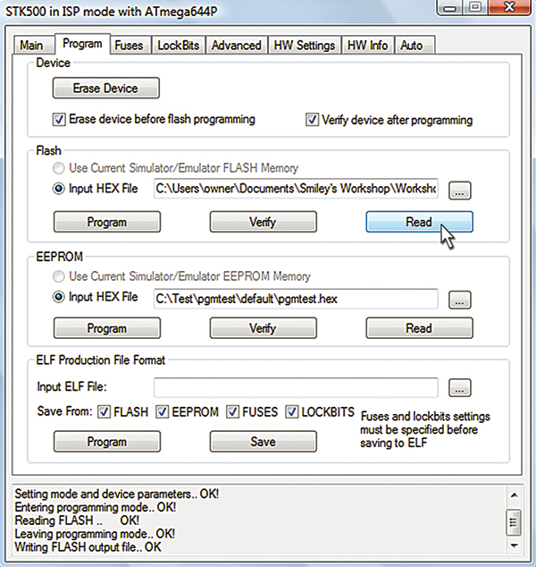
FIGURE 12. Read memory.
To do this, we want to reopen the AVR Programmer dialog as shown in Figure 12, then click ‘Read.’ We are then asked to name the file that will hold the saved data, as shown in Figure 13.
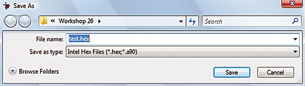
FIGURE 13. Save memory to file.
Now we can open the test.hex file in Programmer’s Notepad [part of WinAVR], scroll down to the memory location for 0x2000 as shown in Figure 14, then we can see our 16 bytes (nested in the Intel Hex formatted line).
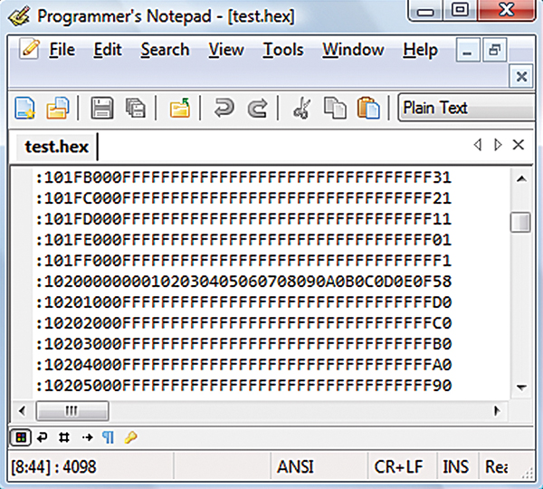
FIGURE 14. Examine saved memory.
Well, that was entirely too much for one Workshop. Next time, we will take what we’ve learned about memory and build a bootloader. NV