A clock project using CMOS logic and seven-segment displays.
There are digital clock projects and there are really digital clock projects. At one extreme are clocks made entirely with individual transistors, resistors, and other discrete components like the aggressively retro kits produced by KABtronics and described in these pages a few years ago [1]. At the other extreme are microprocessor based clocks with many thousands of circuit elements compressed into one or a few integrated circuits. A novel example of this kind of clock appeared in the March 2014 issue of Nuts & Volts [2].
This project lies between these extremes, toward the early end chronologically. It is a straightforward 12 hour clock with CMOS integrated circuits and seven-segment LED displays. The most complicated ICs in it contain several flip-flops and some additional logic. The clock presents the time on a four-digit display — hours and minutes — with the colon between blinking once each second. Two more LEDs indicate AM and PM alternately. Two pushbutton switches allow the minutes and hours to be set, and the whole thing is powered by a small wall supply.
Structure
A digital clock consists of four parts as Figure 1 illustrates.
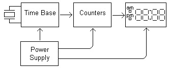
FIGURE 1. The overall design of the digital clock.
A time base provides a signal of fixed frequency whose cycles are counted to mark the passage of time. That signal is derived either from the 60 Hz line frequency or — as here — from a crystal oscillator. Counters count the cycles of the time base’s signal and generate outputs that represent digits. Driver ICs decode these outputs to drive the displays, which show the time. Lastly, a power supply provides the power that the other parts require. In a microprocessor based clock, these functions are almost all carried out by the microprocessor; here, they are distributed among nine integrated circuits and a few transistors.
Time Base
The time base consists of one transistor and two integrated circuits. The transistor — an MPF-102 or similar FET — is used in a crystal-controlled oscillator. Many oscillator frequencies can be divided down to control a clock; here, the crystal’s frequency is 4.194304 MHz = 222 Hz. The variable capacitor in the oscillator is a trimmer; it allows slight adjustment of the oscillator’s frequency so that the clock will keep accurate time.
The first integrated circuit is a CD4521 (or an MC14521) which contains an inverter and a chain of 24 flip-flops. The output of each flip-flop is connected to the input of the next. The outputs of the last seven flip-flops are available. The first flip-flop receives the oscillator’s signal. Each flip-flop divides the frequency of the signal it receives by two, so the output of the last flip-flop is the input frequency divided by 224.
With an input frequency of 222 Hz, the output of the 20th flip-flop is 4 Hz; this signal is used to advance the hours and minutes quickly for setting. The output of the 20 second flip-flop is 1 Hz; this signal blinks the colon on the display.
The output of the last flip-flop is (1/4) Hz; that is, one cycle every four seconds. This signal goes to a CD4029 presettable four-bit binary counter. This counter is preset to 15 by imposing high signals representing binary 1s on its preset inputs, and it counts down so that it divides its input frequency by 15; 4 x 15 = 60, so the ‘4029’s highest-order output completes one cycle every minute. This signal drives the clock’s counters. Figure 2 shows the circuit of the time base.
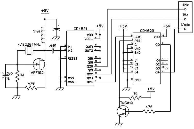
FIGURE 2. The clock’s crystal-controlled time base.
The carry-out output of the CD4029 is used to reload the counter when its count reaches zero. This signal goes high at that time, but the 4029’s preset input is active low. A transistor inverter flips the carry-out signal so that it resets the count appropriately.
I could have used another IC, but that seemed inelegant for just one inverter. The transistor — like others in this project — is a TN3019 because I had a bunch of them. Any general-purpose NPN will do.
Counting
Two of the time signals — 4 Hz and 1/minute — go to the counting circuit. Figure 3 shows this circuit and the display circuit that receives its outputs.
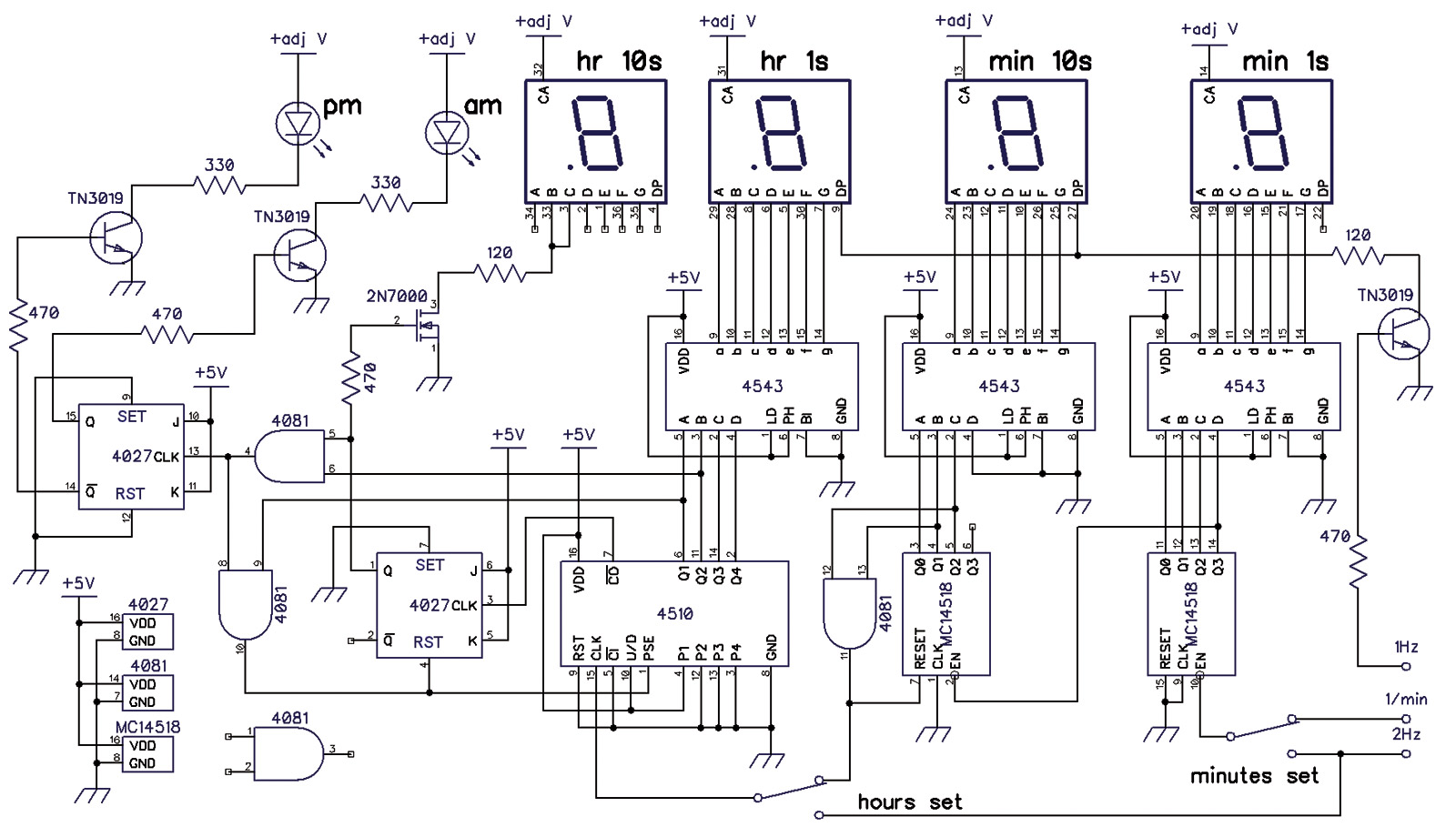
FIGURE 3. The clock’s counting and display circuits.
Counting uses four ICs: a CD4518 dual decade counter; a CD4510 presettable decade counter; a CD4027 dual J-K flip-flop; and a CD4081 quad AND gate. The counters and one of the flip-flops generate signals that indicate the minutes and hours digits. Let’s follow the 1/minute signal from the time base through these ICs.
The 1/minute signal enters one decade counter of the 4518 which counts the minutes and generates a binary-coded decimal (BCD) representation of the minute’s 1s digit at its four outputs. The 8 output of this counter is connected to the input of the second counter in the 4518; when the minute’s 1s count rolls over from 9 to 0, this output goes low and the second counter increments the minute’s 10s count.
BCD and Counting
In digital logic, signals are binary: high and low voltages represent 1s and 0s, respectively. One such unit of information is a binary digit or bit. The 10 decimal digits can be represented by sets of four bits that indicate each digit’s value in binary notation, thus binary-coded decimal (BCD). 0000 represents the digit ‘0;’ 0001 represents ‘1;’ and so on up to 1001, which represents ‘9.’ The four bits are represented by the signals on four lines.
A flip-flop is a digital circuit whose output changes state — from low to high or from high to low — on each complete cycle of its input. Thus, a flip-flop produces an output signal whose frequency is half the frequency of its input signal.
Integrated circuit counters are chains of four flip-flops. The output of each is both an output of the counter and the input to the next flip-flop in the chain. If a signal with frequency f is presented to the first flip-flop, the four outputs have frequencies of f/2, f/4, f/8, and f/16. In the absence of any additional logic — a binary counter — the four outputs together repeatedly count in binary from 0 through 15.
In decade counters like the CD4518 and CD4510 used here, additional logic resets the flip-flops to 0 when the second and fourth outputs — representing 2 and 8 in the count for a total of 10 — are both high. The four outputs cycle from 0000 through 1001; that is, through the BCD representations of the digits 0 through 9.
In the minute’s 10s count, 0 should follow 5 as 59 minutes rolls over to 00. To accomplish this, the 2 and 4 outputs of the minute’s 10s counter connect to an AND gate — one of four in the CD4081. When the minute’s 10s count reaches 6 at the end of an hour and the beginning of the next, its 2 and 4 outputs are high so the AND’s output goes high. This resets the minute’s 10s count to zero and sends a pulse to the next counter — the CD4510 — which counts an hour.
As mentioned, this is a 12 hour clock, so the hour’s 10s digit is always either blank or 1, and we don’t need a full counter to keep track of it; one of the flip-flops in the CD4027 will do the job. When the hour’s 1s count in the CD4510 rolls over from 9 to 0, the 4510 sends a signal to that flip-flop whose Q output goes high to indicate a 1 in the hour’s 10s position.
At this point, things get a little tricky for two reasons. First, the hours count must roll over after 12; that is, the hours count must be reset when it reaches (very briefly) 13. Second, that count must roll over to 1 — not 0 — since 1:00 follows 12:59. Two more AND gates in the 4081 handle the first issue. Together, they notice when the hour’s 10s digit is 1 (the Q output of that flip-flop is high) and the 1 and 2 outputs of the 4510 are high; that is, the hours count reaches 13. The output of the second AND gate goes high which resets the flip-flop — its Q output goes low — and raises the LOAD input of the 4510, whose preset inputs specify a value of 1. (It is possible to accomplish this transition with a non-presettable counter, but it requires more logic. That implementation is left as an exercise.)
The three decade counters and one flip-flop are now correctly counting the minutes and hours indicated by the 1/minute signal from the time base. All that remains is to light up the AM and PM indicators correctly.
It makes sense to assign this task to the second flip-flop in the 4027. It has complementary Q and ~Q outputs, and exactly one of the indicators will be lit at any time. However, morning becomes afternoon and evening becomes morning again at 12:00, not 1:00, so we cannot use the hours-reset signal to toggle this flip-flop. Fortunately, we already have (as Figure 3 shows) an appropriate signal.
One of the AND gates goes high when the hour’s 10s signal and the hour’s 1s 2 signal are both high; that is, at 12:00. This signal goes to the second flip-flop’s input, so that each time the hours count reaches 12 it flips (or flops), turning one indicator off and the other on.
Two pushbutton switches apply the 4 Hz signal to the minutes and hours counting inputs to quickly advance those counts and set the minutes and hours.
Displays
The outputs of the counter stages go to ICs and transistors that drive seven-segment common-anode displays: 3-1/2 digits for the minutes and hours counts, and the colon between the hours and minutes. The minute’s 10s display is mounted upside-down so that its decimal point and that of the hour’s 1s display form the colon. The 1 Hz signal from the time base controls the colon between the hours and minutes through a transistor switch, so the colon blinks once each second.
The details of the connections to the displays depend on the particular displays chosen. These can be four one-digit displays, two two-digit displays, or one display containing all four digits. The pin numbers in the figure conform to the last of these. In any case, consult the display’s datasheet.
CD4543 decoders drive the three lower-order digits. They translate the BCD signals from the counters into signals that turn on the appropriate segments of the displays. The hour’s 10s digit, the colon, and the AM and PM indicators are all controlled by transistor switches driven by the signals from the counters and the time base. A 2N7000 was used to drive the hour’s 10s digit because a 2N3019 didn’t switch in this situation; this is why we breadboard.
Power Supply
Figure 4 shows the clock’s power supply. It begins with at least 7 VDC from a wall supply. A 7805 three-terminal regulator provides regulated +5V for all the integrated circuits. An LM317 provides an adjustable positive voltage for the common-anode displays which require less than 5V. The higher this voltage, the brighter the displays, so the pot that sets this voltage controls the display’s brightness.
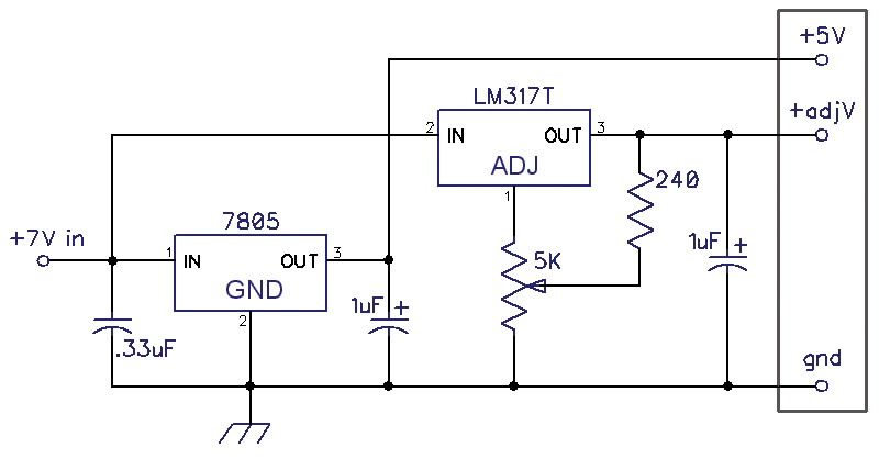
FIGURE 4. The clock’s power supply, with input from a wall wart.
Construction
I could have designed circuit boards for this project and had them fabricated, but prototyping boards (often called proto boards) are handy and convenient for one-off projects. For IC-based projects like this one, my favorite is the RadioShack 276-168 which has rows of three-hole pads separated by two buses, plus some extra two-hole pads on one end.
The recent downsizing of RadioShack means that these boards are not as easy to come by as they once were, but they remain available.
The clock occupies three of these boards. One holds the power supply and the time base, with small heatsinks on the two regulators. A trimpot sets the output voltage of the LM317. The second board holds the counters and their associated logic, and the third holds the drivers, displays, LEDs, and setting switches. All the ICs are mounted in sockets; the displays are mounted on SIP sockets; and all three boards contain several .1 µF bypass capacitors (not shown in the schematics) from +5V to ground.
The board’s traces are not indicated on their component sides, so I chose one bus on each for the ground connection and the other for the +5V supply, and traced them in black and red Sharpie™ on the board’s component sides. The wiring was done with 24 ga solid insulated wire, with red used consistently for all +5V connections and black for all ground connections; do these first. Other colors were used for visibility and clarity.
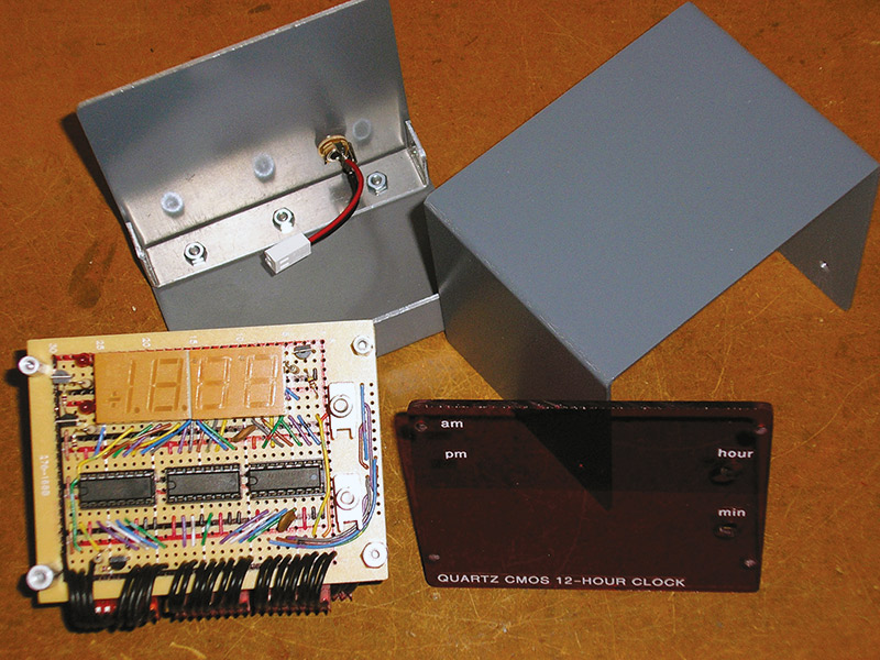
Right-angle headers and connectors attach the boards. With spacers and standoffs between them, the boards form a three-layer sandwich; the connectors allow the sandwich to be easily taken apart for debugging. Figure 5 shows the three boards.
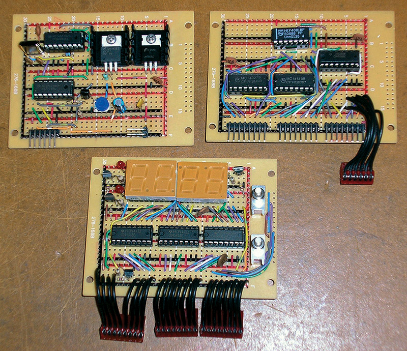
FIGURE 5. The three circuit boards that make up the clock.
The clock’s enclosure is bent up from two pieces of aluminum: one for the base and one for the top. The front panel is a piece of transparent red 1/4” acrylic (Plexiglas), drilled to accommodate four screws at its corners and the setting switches. (When drilling acrylic, enlarge small holes gradually and go slowly and carefully. Drilling too quickly can cause the bit to catch in the material. Clamp the material rather than holding it with your hand. Drill a few test holes first.)
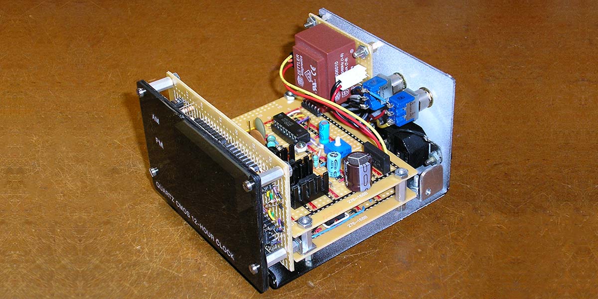
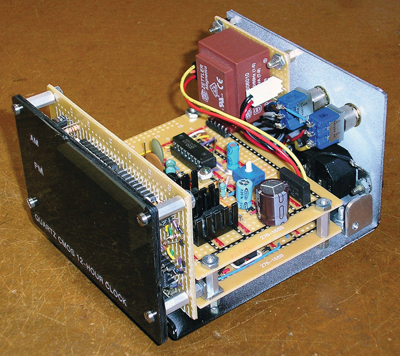
The sandwich of the three boards and the acrylic panel is mounted to the base with two screws at its bottom, where the spacers are shorter than those at the top by the thickness of the acrylic. A connector for the wall supply is mounted on the back panel. Figure 6 shows the inside of the assembled unit.
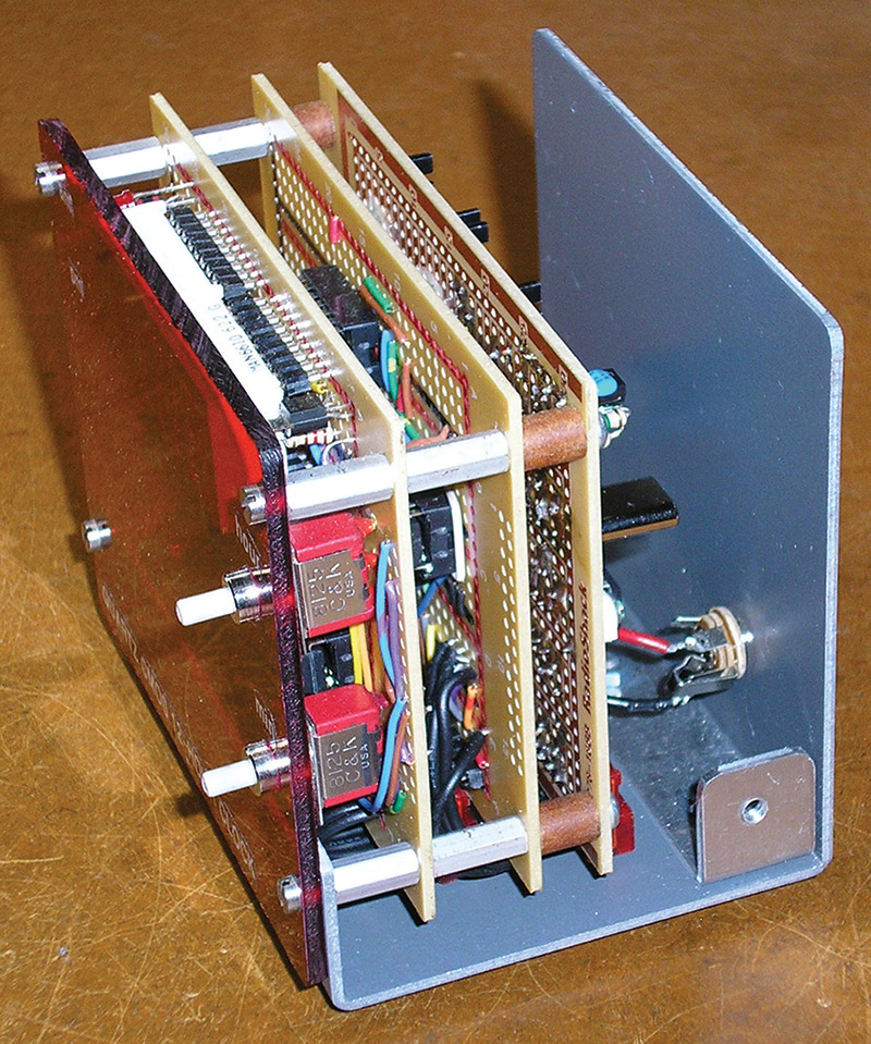
FIGURE 6. The inside of the assembled clock.
Self-tapping sheet metal screws hold the top to brackets at the rear of the base. The metal parts of the enclosure were cut from a salvaged panel painted with lightly textured gray paint. The paint cracked at the bends, but another light coat of gray fixed that and preserved the texture. The minimal labels were made with a Brother label maker. Figure 7 shows the finished clock.
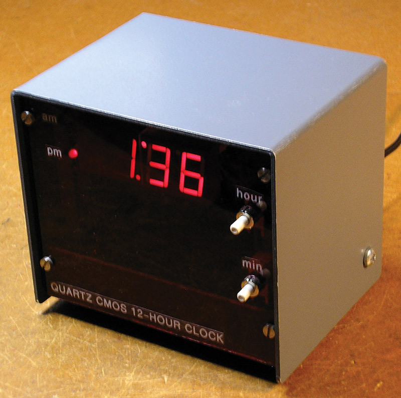
FIGURE 7. The completed clock.
Adjustment
The trimmer capacitor in the crystal oscillator allows slight adjustment of the oscillator’s frequency. Set the clock, determine over a day or two if it is running fast or slow, and modify the capacitor’s setting accordingly. It helps to sketch pictures of the capacitor’s setting, and the process may take a few weeks. Be patient.
A Second Clock
In designing and prototyping the clock I’ve just described, I built a second power supply and time base board. This one requires an input voltage of about 8 VAC, and therefore includes a full-wave bridge and an electrolytic filter capacitor. Also — in place of the CD4029 — it uses a 74C193, also a presettable binary counter which has the advantage of not requiring an inverter between its carry-out output and its load input. Since this board was already assembled and tested, I decided to build another clock using it.
Again, there were three boards: the power supply and time base; a counter implementing the same circuit as before; and a driver and display board. The physical arrangement, however, was different. This time, the power supply/time base and counter boards formed a horizontal sandwich.
The display board — a section of a Datak 12-600B — was mounted to the counter board with long right-angle headers and two small Keystone right-angle brackets, which are threaded for 4-40 screws. (Jameco stocks these brackets as part number 1581530.)
The set switches and a small 8 VAC transformer were mounted on the unit’s back panel, along with a three-wire computer-style line connector. As before, the sub-assemblies connect via headers and connectors, including (in this case) a five-wire connection from the counter board to the switches. The three boards are mounted to the bottom of their enclosure as Figure 8 shows.
 .
.
FIGURE 8. The inside of the second clock.
Figure 9 shows both clocks all put together with a third one of similar (but simpler) design and a 24 hour presentation.
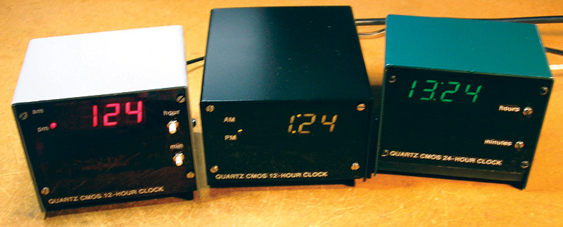
FIGURE 9. The two 12 hour clocks and a 24 hour clock.
Cautions
If the setting switches bounce, setting the clock is an exercise in random numbers; quality switches are a good investment. A project like this contains a very large number of solder joints often close together, so there are many opportunities for cold joints and solder bridges. Build stage by stage and test as you go.
An oscilloscope is very handy for testing and debugging, and it’s interesting to see the waveforms and frequencies at various points in the circuit. You can test with signals of higher frequency than 1/minute. Modules are helpful; it’s good to be able to take the clock apart for testing and debugging.
Variations
Many variations of this general clock design are possible. Different oscillator frequencies can be divided down to the frequencies a clock requires, or a 60 Hz signal can be derived from the 120 VAC line.
Clocks of this overall structure can be built with a variety of integrated circuits. Many counter ICs are widely available and inexpensive. CMOS ICs (4000 series) are far more economical of power than are TTL (7400 series).
A 24 hour clock is simpler than one with a 12 hour display. It rolls over from 23:59 to 00:00, and there’s no need for the AM/PM LEDs, though another decoder/driver IC is necessary. The minutes counting circuit can be preceded by an identical circuit that — beginning with a 1 Hz signal — counts and displays seconds.
The clocks described here draw no more than 150 mA at 5V, with almost all of that going to the displays and LEDs; TTL versions may draw as much as 500 mA, requiring a larger transformer or wall supply, and serious heatsinking for the regulators; mount the heatsinks to the metal back panel.
In any case, read the datasheets of the ICs you select, build and debug a breadboard first, and preserve the breadboard while you build the permanent version. NV
References
[1] Keith Bayern: “Transistor Clock,” Nuts & Volts, July 2009, pp. 42-46.
[2] Craig A. Lindley: “A Unique LED Clock,” Nuts & Volts, March 2014, pp. 33-39.
Parts List
None of the parts are obscure or hard to find. All should be available through major distributors such as Digi-Key and Allied. All resistors are 1/4W.
Time Base:
CD4521 CMOS 24-stage frequency divider
CD4029 CMOS pre-settable up-down counter
MPF102 FET
2N2222 or other general-purpose NPN transistor
4.194304 MHz crystal
1 mH choke
30 pF trimmer capacitor
.1 µF, 16V capacitor
.001 µF, 16V capacitor
1M resistor
1K resistor
2 - 470Ω resistor
Common Anode Counting and Display Circuits:
Seven-segment common-anode LED displays: 4 one-digit; 2 two-digit; or 1 four-digit, not multiplexed.
2 – LEDs
CD4518 CMOS dual up counters
CD4510 CMOS presettable up/down counter
CD4081 Quad two-input AND gate
CD4027 Dual J-K flip-flop
3 – CD4543 CMOS BCD-to-seven-segment latch/decoder/driver
3 – 2N2222 or other general-purpose NPN transistor
2N7000 Small-signal MOSFET
2 – 330Ω resistor
4 – 470Ω resistor
2 – 120Ω resistor
2 – SPDT momentary pushbutton switches
Power Supply:
LM7805 Three-terminal 5V regulator in TO-220 package
LM317T Three-terminal adjustable positive regulator in TO-220 package
2 – 1 µF, 16V electrolytic capacitor
.33 µF capacitor
5K trimpot
240Ω resistor
Miscellaneous:
Enclosure
Tinted transparent acrylic to match the displays
DC wall supply: 7V to 9V
Headers and connectors
Connector for the wall supply
Standoffs
Four rubber feet
Hardware