Learn how to use a CAN bus with a Propeller MCU - Part 1
The Controller Area Network (CAN) began as a communication path for electronic equipment in vehicles. Unlike the RS-232 or RS-485 standards, the CAN standard (ISO 11898) provides electrical specifications and a format for information exchanges. Many newer microcontrollers include one or two CAN controllers that properly format data, set device addresses, provide hardware error detection, and identify communication errors if any. As a bonus, CAN based devices may operate in a multi-master network that uses more than one controller to supervise operations.
Datasheets and documents for CAN based microcontrollers might make them seem complicated to use. Thankfully, MCU manufacturers provide code libraries and examples that can get you off to a good start. You need not understand every aspect of the CAN bus and CAN controllers to communicate between devices. This article will help you learn enough to use basic bus communications in projects. Later articles will supply more details of CAN signals and protocols.
People who use RS-232 type communications understand how positive and negative voltages represent logic 1s or 0s. The CAN bus, on the other hand, uses the voltage difference between two wires — labeled CANH and CANL — to represent logic levels. The SN65HVD251 bus driver, for example, includes a differential driver and a differential receiver (Figure 1).
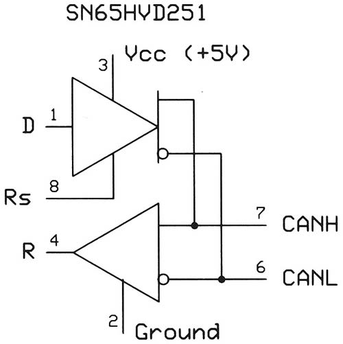
FIGURE 1. An SN65HVD251 provides a bus driver (top) and a bus receiver (bottom). The receiver output always indicates the state of the CAN bus. Ground the Rs input on this device, and do not make a connection to the reference-voltage output on pin 5 (not shown). A CAN bus does not need a common ground between devices (pin numbers for an eight-pin DIP).
When you apply a logic 1 to the driver input (D) on an SN65HVD251 IC, the CANH and CANL outputs will have the same voltage level; about 2.5V for a 5V supply. We call this a recessive state on the bus. A differential receiver — including the one in the SN65HVD251 — would detect no voltage difference between CANH and CANL, so its receiver output (R) would give us a logic 1. Apply a logic 0 to the D input and the CANH output rises to about 4V, while the CANL output drops to about 1.4V to create a 2.6V difference between the two signals as shown in Figure 2. We call this the dominant state, and all differential receivers would produce a logic 0 at their R output.
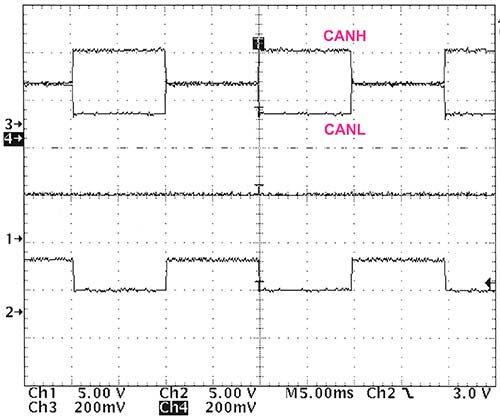
FIGURE 2. An example of a logic signal sent to an SN65HVD251 driver, and the CANH and CANL signals on a terminated bus cable. In this circuit, a logic 1 produces the recessive state in which CANH = CANL = 2.7V. A logic 0 forces the outputs into the dominant state where CANH = 4.1V and CANL = 1.4V for a 2.7V difference.
Even if all other drivers produce recessive signals, a logic 0 input to any driver on the bus will always force the bus into the dominant state. Logic 0s always override logic 1s. Figure 3 shows scope traces for the CANH and CANL signals on a bus with two square wave signals applied to two drivers. A logic 0 input sent to any bus driver input (D) forces the bus into its dominant state. Only when both drivers receive a logic 1 does the bus revert to the recessive state.
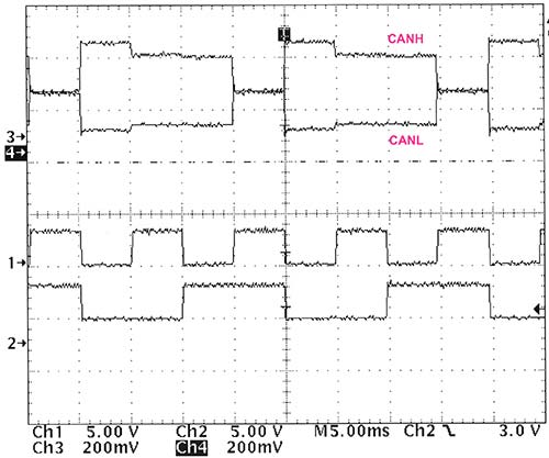
FIGURE 3. The top scope traces show superimposed CANH and CANL signals. The lower two traces show the input’s signal applied to two drivers. Unlike "perfect" CAN bus signals shown in books and application notes, this figure shows measured results on a short twisted-pair bus.
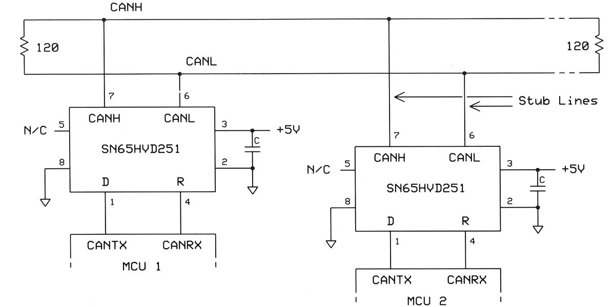
To operate properly and reduce signal reflections on a CAN bus, always use a termination resistor — typically 120 ohms — at each end (Figure 4).
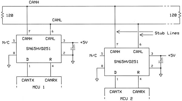
FIGURE 4. Circuit diagram for a portion of a CAN bus. Note the 120 ohm termination resistors at each end. Always limit stub lengths to one foot (0.3 m) or less.
In parallel, these resistors closely match the bus-wire impedance of about 60 ohms. You can create branches off a CAN bus, but limit their length to a foot (0.3 m). As a rule, the longer a CAN bus is, the lower its data rate. For more information, see Note 1 in the sidebar. The scope images shown previously use only test signals, not a CAN formatted frame. Now, we leave the physical bus and explore how CAN communications work.
Identify and Arbitrate
A CAN frame begins with a logic 0 start-of-frame (SOF) bit followed by an 11-bit address that can identify 2,048 unique CAN devices. Networks won’t use that many devices, but each manufacturer of CAN bus devices needs unique IDs for its products, so several thousand addresses make sense. The address — or identifier — also establishes a priority. Address 0 has the highest priority; address 2047 has the lowest.
You know logic 0s on the bus dominate logic 1s, so a logic 0 in an ID overrides a logic 1. Before a CAN controller starts to transmit, it monitors the bus and waits for a bus-idle condition (logic 1). Only then can it start to transmit a frame. What happens if two controllers start to transmit at the exact same time?
Each controller continues to monitor the bus to ensure its output matches what it detects on the bus. Consider the example shown in Figure 5 when two devices start a frame simultaneously.
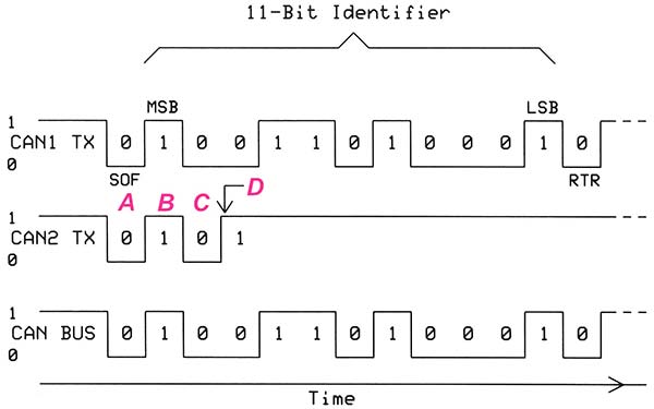
FIGURE 5. A timing diagram for the simultaneous transmission from the CAN1 controller addressed to a device with hexadecimal address 4D1 and from the CAN2 controller addressed to a device with ID 5A0. The frame sent from CAN1 has a higher priority (lower value), so it controls the bus.
Both begin a frame with SOF signals (A) and both detect a logic 0 from their respective receiver. So far, so good; so they continue to transmit. Then, the transmissions follow with a logic 1 most-significant ID bit (B) followed by a logic 0 (C). Again, the transmissions have no problems because the transmitted and detected bus values match the bit value sent from each transmitter.
At point D, the CAN1 TX output transmits a logic 0 and detects a logic 0 on the bus. However, the CAN2 controller detects a logic 0 on the bus as it starts to transmit a logic 1 (Figure 5, arrow). This mismatch causes the CAN2 controller to stop transmission because the CAN1 controller has started to transmit a higher priority ID. We call this process CAN-bus arbitration. Keep in mind the address — or ID — bits in the frame refer to the identification for the recipient device, not the address of the sending CAN controller.
Send the Data
Each CAN frame may include zero to eight bytes of data you can use for any purpose you choose. Bytes could include temperature values, actuator settings, switch-control bits, servo commands, and so on. This information goes to all CAN devices, but only the one with an 11-bit ID equal to the ID in the transmission will accept and save the data in a set of registers or memory locations. Some devices such as commercial CAN based valves, sensor modules, and motor controls have factory-set IDs, or they could have DIP switches users can set for an address. Before your application software can respond to a specific address, you must load address registers — called filters — with the ID or IDs you choose for a device.
An eight-bit PIC18F66K80 MCU, for example, includes a CAN controller that holds six ID “filters,” so you could create six IDs for the controller. Why have more than one address? A designer might assign an address for commands, another address for calibration values, and another address for I/O data. Before a controller saves any data bytes, the 11-bit ID in the received frame must match one of the IDs saved in a filter. CAN controllers also include 11-bit masks that let you ignore individual filter and ID bits. You would use mask bits if you want a CAN controller to accept addresses within a given range. A logic 0 in a mask means the controller ignores the corresponding filter bit and ID bit. A logic 1 in a mask bit forces the filter to exactly match the corresponding ID bit in a received frame.
Figure 6 provides an example for five bits.
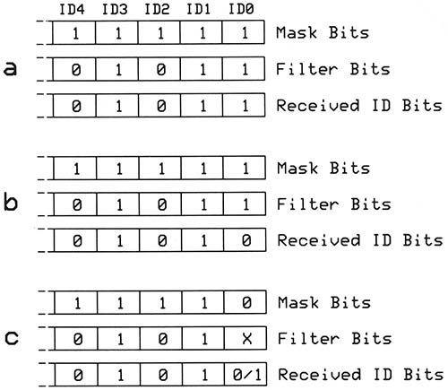
FIGURE 6. Three examples of how a mask bit affects the use of filter bits with a received ID. This diagram includes only the five least-significant bits (LSBs) of an 11-bit ID value. The bits not shown here operate the same way.
In examples a and b, the logic 1 mask bits do not affect the filter bits. The received ID in a matches the filter bits, so the CAN controller saves the received data. The b example shows a mismatch between the filter and the ID bits, so the controller saves no data. Example c shows a logic 0 at bit position ID0 in the mask, which means the corresponding filter bit gets ignored.
Either a logic 1 or a logic 0 at position ID0 in a frame’s ID causes the controller to save the received data. If you had set both mask bits ID1 and ID0 to logic 0 (...111002), what ID range would the controller accept?
For the mask ...111002, the CAN controller could accept data in frames with four addresses: ...11100; ...11101; ...11110; and ...11111. Unless you need a range of continuous addresses for a controller, set all mask bits to logic 1 and set the CAN controller’s ID filters as needed. (Revision 2 of the CAN standard provides for an additional 18 ID bits — a 29-bit ID — for over 500 million addresses. This type of addressing goes beyond the scope of this article.)
Test CANbus Software
Now let’s find out how to transmit and receive CAN frames. I used a Parallax Propeller MCU on a QuickStart board for the following examples because I’m familiar with the Propeller and with its Spin language. You can program it in C or assembly language too. The Propeller IC comprises eight identical processor cores (called cogs) that run independently. One or more cogs can handle CAN related tasks, while other cogs process results or prepare transmissions. Although the Propeller does not have a built-in CAN controller, software libraries offer standard CAN operations, and programmers have created code that works at data rates as high as 1 Mbit/sec.
The test circuit connected the CAN TX output (pin P24) to the CAN RX input (P25) on the same Propeller IC. A 10K ohm resistor from either pin to +3.3V completed the circuit (Figure 7).
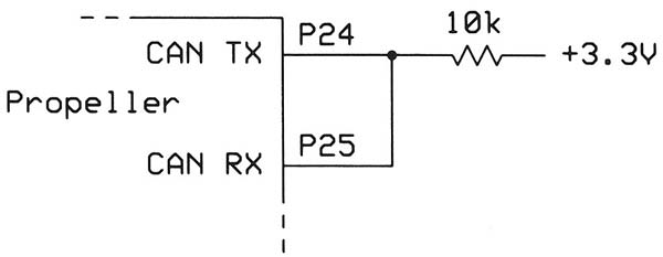
FIGURE 7. Circuit diagram for a loopback test of a CAN transmitter and receiver on a Propeller MCU IC. This type of test does not require a physical CAN bus with drivers and receivers.
For a loopback test, you do not need a complete bus as shown earlier in Figure 4. (Many MCU suppliers connect CAN controllers to specific pins. The Propeller lets you assign any available pins you choose as CAN TX and CAN RX.)
The online free Propeller Object Exchange (OBEX) lists several CAN files with methods that send and receive CAN frames (go to http://obex.parallax.com/object/745). This folder includes a test program, “CANbus Loopback demo.spin” that transmits and receives data frames to test CANbus software. I found this program too complicated for novices, so you can use the simpler test, “CAN Loopback demo JT.spin.” For an even simpler test, see “CAN Loopback demo JT2.spin.” You can find both in the OBEX at http://obex.parallax.com/object/845. (Other MCU suppliers provide similar libraries of CAN software and code examples, although some get quite complicated.)
The free Propeller IDE (integrated development environment) — called the Propeller Tool — lets you open the CAN software, download it to a Propeller IC, run it, and modify it if you wish. The IDE includes the Parallax Serial Terminal (PST) that connects to the QuickStart board via a USB virtual port, which is also used to program the Propeller IC. When you run the CAN Loopback demo JT.spin program, the terminal window displays the information saved by the CAN receiver software (Figure 8).
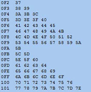
FIGURE 8. This image displays three hex digits for the 11-bit CAN ID, followed by one to eight data bytes as seen in the Parallax Serial Terminal window.
For more information about the Propeller IC and the Spin language, see the Propeller Manual, version. 1.2 (available on the Parallax website at www.parallax.com).
How Does the Code Work?
First, a few words about the Spin language. When you need to use methods in an object file (one with a .spin suffix), you identify the object and then use that name as a prefix to the name of the method you want to use. The Propeller “CANbus Writer 1Mbps.spin” and “CANbus reader 1Mbps.spin” object files include many CAN-control methods. To use them, give the object file a name:
OBJ<br />
    writer : “CANbus writer 1Mbps”<br />
    reader : “CANbus reader 1Mbps”
Then, you identify the methods in the object file this way:
writer.Start (25, 24, 1_000_000)<br />
reader.loopback(true)
Now consider key methods that send and receive CAN frames. For more details, review the listings for the reader and writer object files noted above.
CAN Writer Methods
Located in object file: “CANbus writer 1Mbps.spin:”
1. Start(rx_pin, tx_pin, bitrate)
Define the CAN-TX and CAN-RX pins, and set the bit rate.
2. Send(ident, bytes, d0, d1, d2, d3, d4, d5, d6, d7)
Create and send a CAN frame with an ID value and as many as eight bytes of data.
3. CheckReady
This method returns a true condition if the transmitter-busy and error-detect bits are clear.
4. Stop
Stop CAN operations.
CAN Reader Methods
These methods provide a place to start when you create programs of your own. Keep in mind you must turn on and initialize the receiver and transmitter in any CAN based device you program. You cannot have “receive only” or “transmit only” devices on a CAN bus.
As I’ll explain in a future article, the receiver plays an important role in a transmission. Located in object file CANbus reader 1Mbps.spin:
1. Start(rx_pin, tx_pin, sync_pin, bitrate)
Define the CAN-TX and CAN-RX pins, and set the bit rate. The sync I/O pin lets the two cogs synchronize operations via an I/O connection. Software can use the pin to communicate between tasks. If both cogs start successfully, this object returns the base address of the received data array. If the cogs do not start, the start method returns the false condition.
2. ID
Returns the Ident (ID) value, but does not wait for an ID value to appear in the receiver buffer memory. It returns the false condition if no ID was stored.
3. DataLength
Returns the number of data bytes in a CAN frame.
4. ReadData
Returns the contents of the data buffer, starting with the first byte. Successive use of this method returns the following bytes; second, third, and so on. It does not return “out-of-date” or old data. If the current data buffer contains only one byte, this method returns the value in byte 0, and false for the remaining bytes 1 through 7.
5. DataAddress
This method returns the address of a length-prefaced string that contains the data in the current receiver buffer.
6. NextID
Returns the Ident (ID) value in the next buffer, but it does not wait for an ID to appear. It clears the previous ID to zero. You use this method to advance to the next data buffer.
7. SetFilters
Set your mask value (if any) and as many as five filter values.
8. Stop
This method stops the CANbus reader 1Mbps object and frees the reader and the cogs for other uses.
What’s Next?
A CAN controller has more capabilities than covered here. It will acknowledge receipt of a frame, identify frame errors, keep bit-timing clocks synchronized, and identify any defective CAN controllers on a bus. I’ll discuss those and other topics in Part 2. NV
Resources
The Propeller Object Exchange (OBEX) lists several CAN files with methods that send and receive CAN frames; go to http://obex.parallax.com/object/745.
For an even simpler CAN test, visit http://obex.parallax.com/object/845.
For more information about the Propeller IC and the Spin language, see the Propeller Manual, version. 1.2 available on the Parallax website www.parallax.com.
Notes
1. Corrigan, Steve, "Controller Area Network Physical Layer Requirements," SLLA270. Texas Instruments, 2008; www.ti.com/lit/an/slla270/slla270.pdf.
2. Voss, Wilfried, "A Comprehensible Guide to Controller Area Network," Copperhill Media, Greenfield, MA, 2008. ISBN: 978-0976511601; http://copperhilltech.com/technical-literature.
Downloads
What’s in the zip?
Spin Code for CAN Bus