All microcontrollers require a clock or oscillator to guide a program through its paces. It's the duty of such a module to indicate when an instruction should be fetched from program memory, decoded, and acted upon. Actually, even the simplest instruction is made up of a number of operations that must be sequenced in just the right order and at just the right moment. The clock, then, is like the conductor of an orchestra, coordinating all of the parts that make up the whole.
Since the clock is so important, PIC microcontrollers offer a broad range of options to choose from for your own applications. You can have clocks that run rapidly when a lot has to happen in a short span of time, or ones that consume negligible power for battery-operated rigs. Maybe synchronizing the PIC to a stable real time clock is important to you. In fact, there are eight or more clock options for the typical PIC.
However, if you grab the datasheet and try to sort out all the possibilities, you'll quickly come to rue that old phrase, "Can't see the forest for the trees." Datasheets for PICs run in the hundreds of pages and aren't necessarily organized for best learning. And, of course, the occasional error works its way in, making it even harder for the newcomer to get up to speed.
As someone who has spent his entire adult life in teaching, I've always intuitively valued the importance of a well organized presentation. You begin with the "forest" and only approach the "trees" afterwards. That's what we'll do here — getting the big picture in mind first and then tackling the details when they're finally needed.
So, if you've been dismayed in the past at how complicated the clock options for PICs seem to be, tag along now and see how the right approach can make all the difference. To turn this into an active learning experience, we’ll conclude with some actual experiments you can conduct on the breadboard. By the end of our session together, you should be all set to start using PIC clocks with confidence.
Primary Clocks
To keep things concrete, I'll focus on the PIC16F88 which is one of the most popular of all microcontrollers among DIYers. However, other PICs will sport many of the same options — even the smaller eight-pin chips.
The first concept to nail down is that the PIC can run either on a primary clock or a secondary clock. The former accounts for most situations. In particular, a typical project contains a single clock guiding the microcontroller along and that's the end of the matter. In more advanced applications, we may want a secondary clock to kick in whenever the primary clock is out of the scene. There are several reasons for desiring such redundancy, and we'll explore them in just a bit.
For now, let's focus on the primary clock which is all we need for most projects. Refer to Figure 1 which shows what's available.
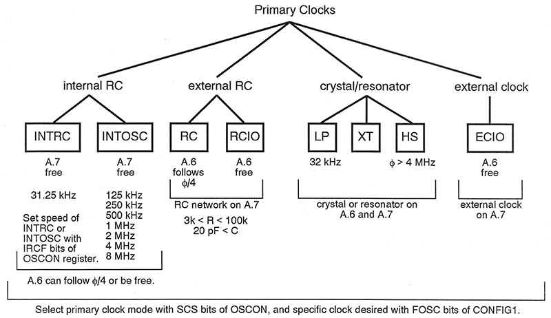
FIGURE 1. The eight modes for a primary clock.
This tree diagram organizes the types of primary clocks available within the PIC16F88 in a top-down fashion. To begin, look at the first branches of the tree diagram. A clock can be an internal RC affair or, if you prefer, you can supply your own resistor and capacitor and end up with an external RC arrangement. For situations that demand more precision, an external crystal or ceramic resonator can be employed. Lastly, if you'd like, you can drive the PIC with an existing external clock.
Adding a bit more detail now, the branches of the tree split again showing the eight individual modes. Each has an abbreviated name given to it by Microchip. These are worth learning now to simplify reading the datasheet later on. Let's scan these specific modes from left to right. The first is INTRC which stands for internal RC oscillator. Running at an approximate 31 kHz, this is a low speed affair built inside the PIC. While that's pretty slow by any standards, it does have the advantage of being simple and consuming very little current.
The next mode is INTOSC. Like INTRC this is internal (requiring no outboard components), but can run at seven different speeds all the way up to 8 MHz. In some of the PICs, INTRC and INTOSC are truly independent, but not so in the PIC16F88 we're examining. For this reason, in the datasheet the writers sometimes use INTRC to mean INTRC only and at other times to signify either INTRC or INTOSC. That only adds to the confusion, so I'm going to keep the names separate here.
In either of these modes, port line A.6 can be configured to follow the clock divided by four if desired. This is symbolized φ/4 — read "phi divided by four." Use this output if you'd like to synchronize some external gear to the micro. The datasheet calls this mode INTIO1, if you're curious. Otherwise, you can optionally free up pin A.6 for ordinary digital I/O, referred to as INTIO2 mode.
Moving to the external RC modes, the first is simply called RC. In this case, an external resistor and capacitor on pin A.7 get things going. Assuming a +5V power supply, the resistor should lie between 3K and 100K, while the cap should be greater than 20 pF. With the smallest values, the clock will max out at around 4 MHz. Like we saw with the internal clocks — if desired — A.6 can be caused to follow φ/4 (that's RC mode) or else be free for ordinary use (that's RCIO). Incidentally, the resistor could be a potentiometer wired as a rheostat which would give you a variable clock.
Crystals and ceramic resonators are attractive since they're much more accurate both in the short term and long term, and also with respect to tolerances and temperature. There are three modes here. The first, LP — which stands for low power — is meant to be used with a 32.768 kHz tuning fork type crystal. These pop up commonly in wristwatches and real time clocks. The crystal and associated load capacitors connect to pins A.6 and A.7. The next mode — called XT — is similar but meant for use with higher frequency crystals and resonators up to about 4 MHz. The last mode is HS — standing for high speed — and is needed for crystals or resonators cranking above 4 MHz. Just so you know, the upper limit for the PIC16F88 is 20 MHz. What's neat about these three modes is that the chip automatically selects the correct gain of the internal driver to the crystal based on whether you specify LP, XT, or HS.
The last mode is ECIO which simply lets you pump in an external clock signal on pin A.7. This could come from any sort of clock circuit that puts out square pulses swinging from ground to the supply voltage.
Peeking ahead just a bit to the experiments, Figure 6 shows the hardware arrangements involved. We'll see how to stipulate any of these eight modes in just a moment, but first let's take a look at the secondary clock options.
Secondary Clocks
Figure 2 shows a branching tree diagram for the available secondary clocks. Recall that any of these can take over duties from the primary clock under certain circumstances. The datasheet likes to group these into the categories RC_RUN and SEC_RUN, but both indicate secondary clocking.
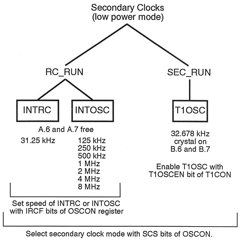
FIGURE 2. The three modes for a secondary clock.
There are two choices for RC_RUN. Either the INTRC or INTOSC internal clocks described earlier can be used; the only difference really being the rate of oscillation.
Or, if desired, you can attach the 32.768 kHz crystal and load capacitors to B.6 and B.7. What’s so cool about this is that the watch crystal always runs — even when you put the chip into what's known as sleep mode. This mode — designated T1OSC — is ideal for real time clock applications. (Normally, the PIC will shut down unused clocks when going to sleep).
Observe that primary clocks use A.6 and A.7 in various combinations, but secondary clocks do not — at least for the PIC16F88. The schematic in Figure 7 (for one of the experiments coming up) shows what's involved.
With that, we've concluded our overview of the primary and secondary clocks. Why not take a few moments to study Figures 1 and 2 once more to really fix the distinctions and details in your mind before proceeding.
How to Make Your Selection
So, you've decided what kind of clock you want. Now, how do you express your wishes to the PIC? The answer lies in the configuration bits and three special registers. The configuration bits are set during the burning (Flashing or programming) phase, while the register bits are accessible during runtime. Here's the scoop.
Figure 3 illustrates the two sets of configuration bits within the PIC16F88. (Simpler PICs only have one set.) Yes, there's a lot here, but when it comes to setting up the clock only a handful need concern us. For example, the three bits labeled FOSC designate the primary oscillator as described earlier. In other words, these establish the default behavior on power-up.
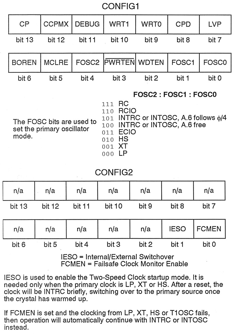
FIGURE 3. Configuration bits are set when the PIC is burned.
In the second set of configuration bits, you'll find two that govern what will happen when you switch over from the primary to secondary clocks, or vice-versa. We'll save that for the next section.
Once a program is running, you can manipulate the clock (or clocks) in various ways by modifying the registers OSCON, OSCTUNE, and T1CON. These are shown in Figure 4. Let's ponder the details.
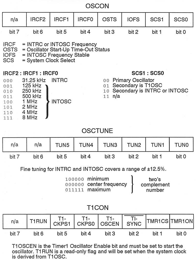
FIGURE 4. These registers can be changed during runtime.
Perhaps the most important bits in OSCON are the ones labeled IRCF, which stands for internal RC oscillator frequency. As the name suggests, these bits select the desired clock rate of the internal oscillator(s). Next up are the two bits labeled SCS, denoting system clock select. Here, you can choose to use the primary or secondary clocks. It's no big surprise that the register OSCTUNE lets you fine-tune the INTRC or INTOSC clock frequency. (On some PICs, only INTOSC is affected.) A six-bit two's complement number is all it takes. Negative numbers slow the clock down, while positive ones speed it up. Tuning over a range of ±12.5% is possible.
The register T1CON concerns itself with controlling Timer 1 which is typically clocked by an external 32.768 kHz crystal which can also do double-duty as the system clock. You might remember this as T1OSC mode from Figure 2. The important flag here is T1OSCEN which enables the Timer 1 crystal oscillator.
At this point, we've hit the fundamentals of clocking the PIC for most common situations. Let's finish up by taking a brief look at the secondary clocks and what they're good for.
Clock Switching
The day may come when you'll want to go beyond just turning on a primary clock and letting it do its thing. If so, then you'll need to know a little bit about clock switching. Figure 5 gives the big picture. Essentially, you can manually switch between primary and secondary clocks, or do so automatically under certain conditions.
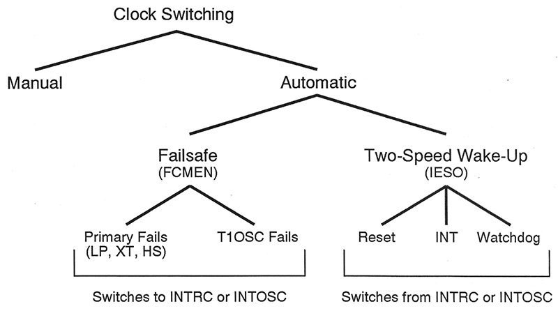
FIGURE 5. Clocks can be switched between primary and secondary modes.
To manually switch from one to another, you're back to Figure 4 and simply need to alter a few bits in the three registers described there. For example, to change from INTRC to INTOSC, you'd adjust bits IRCF0 through IRCF2 as required. Or, to go from a crystal oscillator, say, to INTOSC, head to SCS0 and SCS1 which let you flip back and forth from primary to secondary. You get the idea; manually switching oscillators is just a matter of bit-twiddling in your program.
So, what about automatic switchovers? Well, there are two situations in which it's handy to have one clock take over for another. The first is the failsafe mechanism. Imagine you're designing a circuit to operate in a critical environment in medicine or industrial safety monitoring, for example. If the primary oscillator was a crystal, for instance, and it failed for some reason, then the PIC would simply come to a standstill. Not good! With a secondary clock in the wings, the chip could switch over to it almost seamlessly and still keep operating until the original fault could be attended to. As Figure 5 shows, the failsafe feature can check for problems with any of the four crystal modes (LP, XT, HS, or T1OSC). It's enabled via the FCMEN bit in CONFIG2.
If avoiding delays is a concern, then the two-speed wake-up option might prove useful. Here's the basic idea. Suppose you were operating the circuit on a crystal. As you probably know, crystal oscillators take a moment or two to warm up. The PIC understands this and patiently waits a bit before letting the clock start shooting the instructions through the pipeline. In other words, your project is just sitting there doing nothing for a few moments. On the other hand, the internal oscillators INTRC and INTOSC are essentially put in gear instantaneously. So, why not choose one of these to serve as a secondary clock?
Now, the sequence will be that the internal oscillator handles everything (possibly at a slower rate, but a least it's moving!) until the crystal is ready to assume the mantel of system clock. The switchover is automatic and there's no dead time where nothing is happening.
When is this needed? As intimated earlier, PICs support a sleep command. When executed, the power hungry stuff is shut down and the chip idles in a very low current state. In particular, any crystal being used as a primary clock is halted. Various signals like a reset, an interrupt, or something called the watchdog timer can wake the chip up again. If you want some instant action while the crystal revs up, then consider the two-speed wake-up just described. To enable this response, go to the IESO bit in CONFIG2.
The Experiments
With that, we've covered the essentials of clocking the PIC. There are other niceties you can worry about later, and that's what datasheets are for. At this point, you'll at least be able to handle most common situations, and be in much better shape to actually read that dang thing!
To really cement what you've learned in place, you're encouraged to try the baker's dozen of experiments described in the sidebar below. You will literally learn by doing. Figures 6 and 7 depict the hardware setup, while the PIC16F88 software is taken care of by the source code available from the download files at the article link. The programs are written in the free open source Great Cow Basic language, but are easily ported to PICBasic and other languages. In each experiment, the source code includes lots of comments to help you along, and also describes what to do in order to interpret the results.
Give these a try and see for yourself that clocking a PIC isn't nearly as gruesome as you might have once thought! NV
The download file for this article contains the source code for 13 experiments using the common and inexpensive PIC16F88 microcontroller. The exercises demonstrate all of the various clock modes. The programs are well documented and contain instructions on how to set things up and what to look for. The hardware arrangement for Experiments 1 through 12 is depicted in Figure 6, while Figure 7 shows what's needed for Experiment 13.
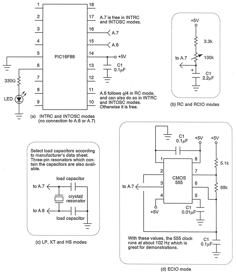
FIGURE 6. Here are the hardware details for primary clocks.
In Experiments 2, 4, and 6, use an oscilloscope or frequency counter to monitor φ/4. In all cases, an LED is blinked just to give the PIC something to do.
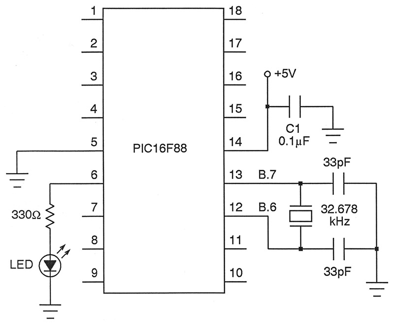
FIGURE 7. T1OSC mode uses a watch crystal as a timebase.
List of Experiments
| # |
Feature Illustrated |
Source Code |
| 1 |
INTRC, A.6 free |
INTRC.GCB |
| 2 |
INTRC, A.6 follows φ/4 |
INTRC.GCB |
| 3 |
INTOSC, A.6 free |
INTOSC.GCB |
| 4 |
INTOSC, A.6 follows φ/4 |
INTOSC.GCB |
| 5 |
RCIO, A.6 free |
RC-RCIO.GCB |
| 6 |
RC, A.6 follows φ/4 |
RC-RCIO.GCB |
| 7 |
LP, low power 32.768 kHz crystal |
LP.GCB |
| 8 |
XT, medium power 4 MHz crystal |
XT.GCB |
| 9 |
HS, high speed 19.6608 MHz crystal |
HS.GCB |
| 10 |
ECIO, 555 timer external clock |
ECIO.GCB |
| 11 |
Failsafe, yank crystal, and see INTOSC take over |
FAILSAFE.GCB |
| 12 |
Switching from secondary to primary on reset |
SWITCHING.GCB |
| 13 |
T1OSC as a secondary clock |
T1OSC.GCB |