The Kill-A-Watt EZ is a very low priced digital AC power meter with logging features. It is very useful around the home and shop for measuring energy use and power consumption of 120 VAC devices. It will measure current, voltage, real and apparent power, frequency, and power-factor (PF). For most appliance measurements, one is only interested in real power (what you pay for!) and possibly PF. However, this device could be used for a lot more in the shop and/or on the bench. I do a lot of work with power transformers, and two very common tests to characterize them are open-circuit (OC) and short-circuit (SC) tests. From these tests, the resistive and reactive transformer parameters are determined.
While the transformer testing process is outside the scope of this article, the conditions for OC and SC testing bare directly. OC testing looks at full voltage, low input current, and no-load current (open secondary) conditions. SC testing looks at low voltage, high input current, and no-load voltage (shorted secondary) conditions. The Kill-A-Watt has the potential to provide all of the measurement parameters needed for both OC and SC testing, except for one problem. It is designed to operate at a full AC voltage (nominally 120V). If this voltage drops below about 60 VAC (say via a variac autotransformer Figure 1), the simple internal DC supply for the microcontroller begins to fail, and the power meter displays erroneous results.
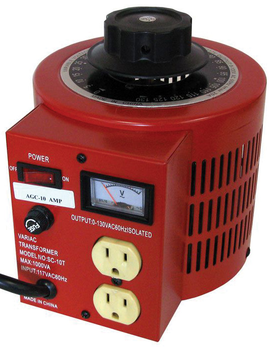
FIGURE 1. A typical variac transformer. Photo courtesy of allelectronics.com.
OC tests work fine as full voltage is used, but for SC testing only enough voltage is used to drive the transformer to the rated input current. This may require only 10%-20% of full voltage, and the stock power meter will not work with such a low input voltage.
This article describes a simple modification that safely powers the meter for accurate operation in this low voltage regime.
Open the Meter
The lead photo shows the Kill-A-Watt EZ model 4460 front. Notice it is not plugged in! Nothing inside is isolated. Three screws on the back will separate the covers and provide access to the two internal circuit boards. Figure 2 shows the inside of the top with the AC board separated.
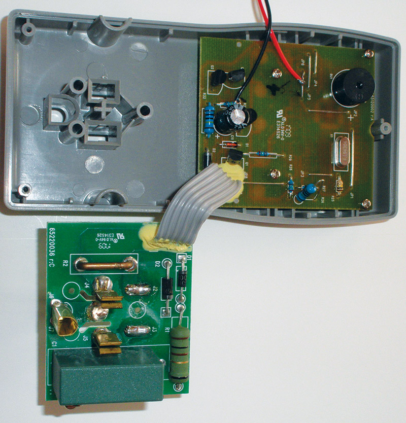
FIGURE 2. The internal PCBs: low voltage PCB on the top right; AC section on the lower left.
We will make no changes to this printed circuit board (PCB). The controller board is to the right and does not need to be removed from the case. The microcontroller (not visible from the top side) requires a standard 5 VDC power supply. Derived in part from a dropping resistor on the AC PCB, it fails when the input AC is too low. Though the internal supply uses a 78L05 voltage regulator already, we will add another regulated, switchable, and battery powered supply for the low AC region of operation.
The schematic of Figure 3 shows the simple LM78L05-based supply which is powered through a pushbutton from a 12V "N" size cell.
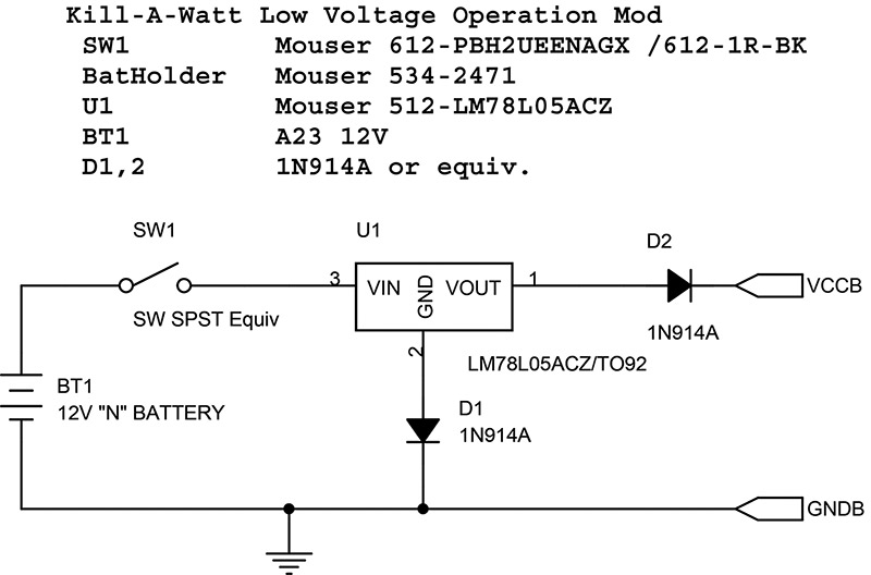
FIGURE 3. Schematic and parts for modification circuit.
The output diode (D2) provides isolation and the ground diode (D1) compensates for the output diode voltage drop. The entire circuit fits on a small perf-board so that the only "permanent" modification is drilling a hole in the top of the back cover for the pushbutton actuator.
Make the Mods
In Figure 4, there are two wires visible (red and black) connected to the Vcc (+5V) and digital ground for the controller. Insure that your K-A-W PCB matches the layout in the picture. Specifically, jumper JP6 = VCC and the top end of R33 = digital ground.
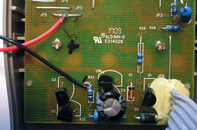
FIGURE 4. Power connections.
Figure 5 shows the N size battery holder epoxy-mounted into the top of the back cover. Note the orientation and fit.
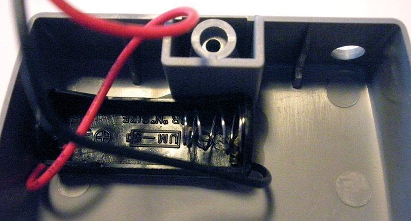
FIGURE 5. Battery holder mount.
The Circuit Board
The new power supply board is only slightly larger than the latching pushbutton. The exact size will depend on the chosen button. Any latching plastic insulated tip single-pole single-throw (SPST) equivalent will do. Repeat: Don’t use a metal switch! Don’t drill the button hole until the board is completed.
Then, cut the hole to match the fitted board. Note the output diode (D2) on the right and the offset diode (D1) under the 78L05 regulator (Figures 6a/6b).
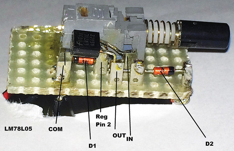
FIGURE 6A. Assembled switch PCB.
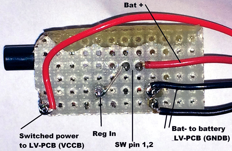
FIGURE 6B. Underside of the assembled circuit board.
This board is assembled with push-pins, but any hand-wired method will work.
Figure 7 shows the circuit board in position in the upper right corner of the plastic back. I held the board in position with a dab of hot glue.
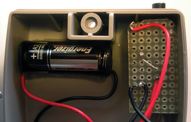
FIGURE 7. Installed battery and PCB.
There is sufficient room in the case for all these components, but upon reassembly, insure that the loose wires are positioned above the controller PCB and do not loop down into the AC board area. Final layout for the project is shown in Figure 8.
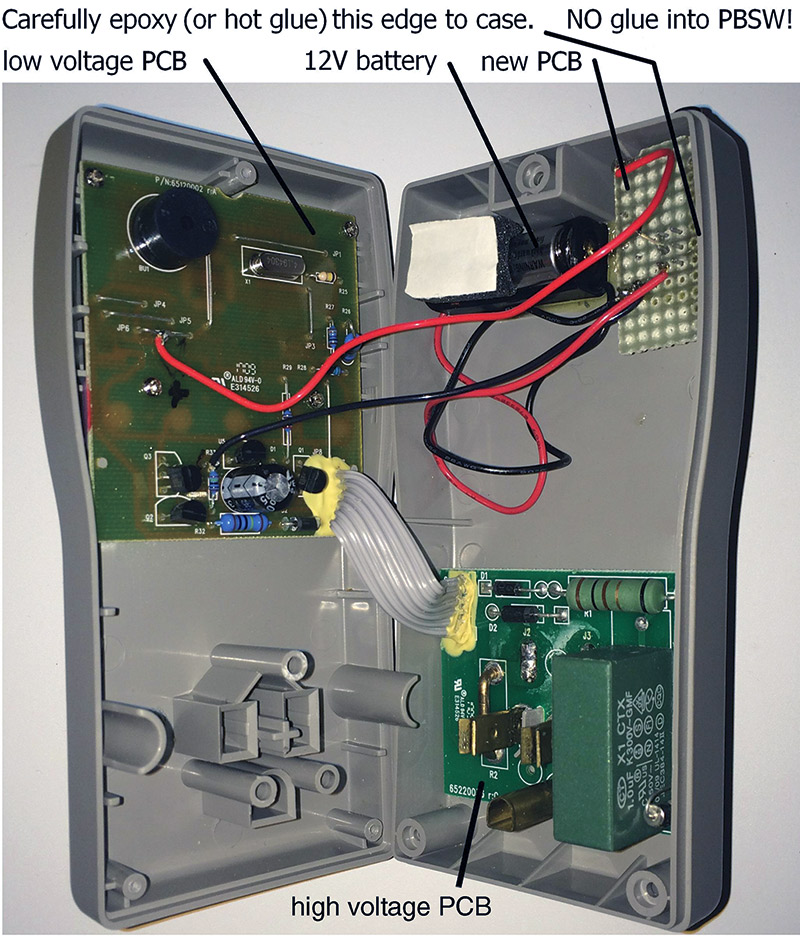
FIGURE 8. Final assembly layout before reassembly.
Operation
The switch specified in the BOM is a latching type push-on/push-off button. The K-A-W internal accuracy fails around 40 VAC, so the circuit should be engaged when the incoming line voltage drops below about 50 VAC. Since I am usually working in the 10-50 VAC range, I leave the battery engaged for the duration of my measurements. But do not forget to disengage the battery when done.
Since the response of the K-A-W to the battery is almost instantaneous, one could use a momentary button instead, and inherently save on battery life. However, one may also need their fingers elsewhere when making measurements.
The K-A-W draws 7 mA at 5 VDC (from LM78L05) at the digital PCB, and 9.7 mA from the 12V battery. A 2-3 mA bias is typical for the LM78L05. Note that on my K-A-W units, the internal power supply sits at 4.95V even at 120 VAC in, so the LM78L05 circuit at 5V is always supplying the PCB power if engaged. Some readers may be tempted to use a lower bias current regulator. Remember, however, that the bias current in the regulator sets the output voltage compensation drop at D1.
Skipping the math, if the currents in D1/D2 differ by a factor of 10, their voltage drops will differ by ~100 mV. Be aware, as that will lower the output voltage to maybe 4.9V and may affect the K-A-W performance.
Caveats
I have had these Kill-A-Watt EZ units for a while. It is possible that the current production from P3International/Prodigit is different, but access to the +5/gnd is all that is needed. Careful tracing will locate them.
A caution to reiterate: There is no AC line isolation in this meter! All digital circuits are floating at the line voltage, so don’t plug in the meter to make internal measurements. Use an isolation transformer instead. Don’t make modifications that protrude beyond the case if they are conductive; hence, the use of an insulated plastic pushbutton. NV
Tip: In assembling the PCB, I found it easier to glue in the PCB before attaching the connecting wires to the rest of the K-A-W.
Tip: Don’t forget to turn the circuit off when not in use. The 78L05 idles at 3-5 mA, so the A23 won't last forever. There are other 5V regs with lower idle and lower drop-out.