The humble incandescent light bulb doesn't get much respect anymore. Facing extinction in many countries and being replaced by more modern and efficient alternatives like LEDs, the uses for these incandescent lamps are few these days. The long time electronics hobbyist (like me) is often left with drawers full of bulbs with no obvious use for them. And yet, for all their failings and inefficiencies, incandescent lamps still hold a nostalgic place in the heart of many electronics hobbyists who still love the soft warm glow of a light bulb. Can we save them from their fate and give them a new life?
This is the story of how I saved some of my light bulbs from extinction by building a useful lab tool with them: an adjustable electronic load.
The Need for Adjustable Electronic Loads
An adjustable electronic (power) load is a very handy piece of test equipment in the development of electronics projects. For example, when you are building a power supply, there will come a time when you need to “simulate” a load to see how well your design performs. To properly test a power supply, an adjustable load is just the ticket. It allows you to measure how much current the supply can deliver at a given output and input voltage, and measure important parameters such as efficiency, regulation, and ripple under various load conditions.
In the old days, I sometimes would use an incandescent light bulb as a crude power load when testing a power supply. Light bulbs were easy to find and could draw a lot of current — which is actually an advantage in this application. However, I would often be limited by the choice of light bulbs available at hand.
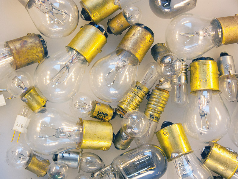
FIGURE 1. Incandescent light bulbs.
Controlling the amount of current drawn from the supply under test was a trial-and-error affair at best. Then, it occurred to me: What if I could make a sort of “variable incandescent DC load?” This would be a very useful tool for me, and I would use my long abandoned incandescent lamps ... a win-win situation!
Traditional versus PWM Adjustable Loads
There are a few different ways to build an adjustable electronic load. A traditional approach (and one that I built myself in an earlier project [1]) uses one or more power MOSFETs in parallel as load element(s). The top diagram in Figure 2 shows a simplified version of this traditional arrangement. By adjusting the MOSFET’s gate voltage (typically with a DC signal), the MOSFET resistance from Drain to Source changes so you effectively get an adjustable load (resistance) from the “INPUT” perspective.
Note that in these types of circuits, the MOSFETs dissipate most of the power and heat, and thus need to be fitted with adequate heatsinks. You might even need cooling fans. (The circuit may also require a power sense resistor if some sort of feedback loop or measurement is implemented, but I will stick to an open loop strategy here for simplicity’s sake.)
The bottom circuit in Figure 2 shows the strategy I employed instead.
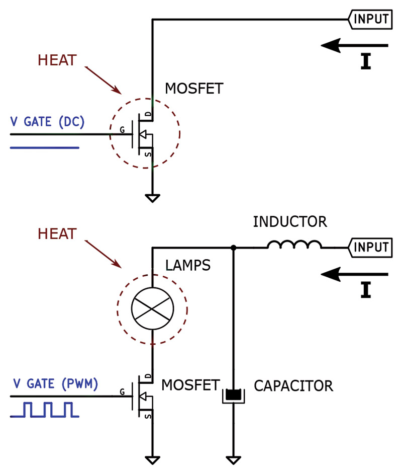
FIGURE 2. Traditional versus PWM adjustable loads.
The incandescent lamp(s) are placed in series with a MOSFET. Rather than applying a DC control circuit to the gate, I applied a variable duty cycle PWM signal. As the duty cycle increases, so does the average current through the lamps, so you get — in effect — an “adjustable load.” However, this wouldn’t be a very useful circuit if we didn’t filter the abrupt changes in current from the load as the MOSFET turns ON and OFF. This is the function of the series inductor and capacitor in the figure which form an LC low-pass filter. These components are absolutely crucial here.
To illustrate this, I measured the current through this circuit with and without the series inductor using a small 0.1Ω series sense resistor and an oscilloscope (the capacitor remained in the circuit). The results are shown in Figure 3. Without the inductor, there is over 1A of peak-to-peak ripple current (one vertical division in Figure 3 corresponds to 1A).
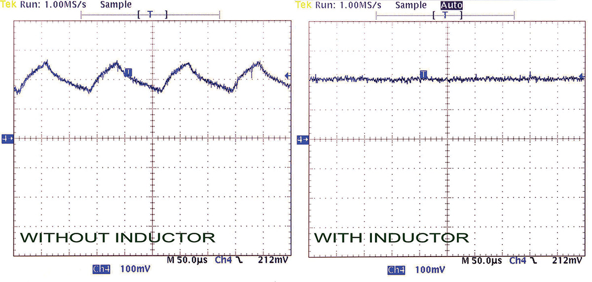
FIGURE 3. Load current with and without inductor.
As it’s clear from this figure, the inductor makes the whole load circuit behave more like a variable resistor from the ‘supply under test’ INPUT standpoint (remember that inductors tend to ‘oppose’ sudden current changes). The measured input current is very much a DC signal without appreciable ripple, which is our goal.
It’s important to note that — unlike in the traditional approach — most of the heat in this circuit is dissipated in the incandescent lamps instead of the MOSFET. Since the MOSFET is either turned OFF (close to infinite resistance) or turned ON (close to zero resistance), the power dissipated in the device is much lower than with the traditional circuit. The incandescent lamps do the heavy lifting here and dissipate most of the heat. Plus — unlike the MOSFETs — incandescent light bulbs do not need large heatsinks!
Furthermore, you get visual indication that the current is flowing through the lamps, which I find is satisfying and advantageous user feedback in this sort of test equipment.
Circuit Diagram
Figure 4 shows a block diagram for the circuit, whereas Figure 5 shows a schematic diagram.
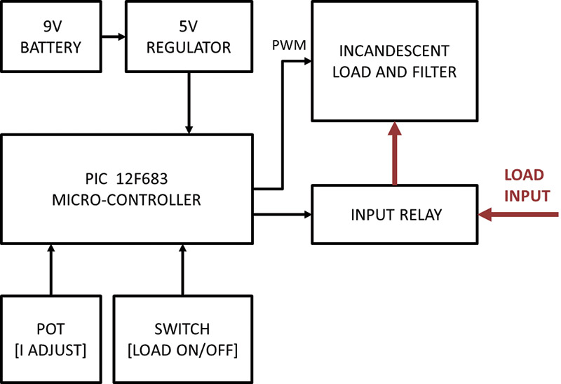
FIGURE 4. Block diagram.
An eight-pin PIC12F683 microcontroller (U2) is used to provide the PWM signal to the gate of the MOSFET. The internal ADC (Analog-to-Digital Converter) reads a voltage from a multi-turns potentiometer (POT) and adjusts the PWM duty cycle proportionally. You could instead use two potentiometers in series (one for ‘coarse’ adjustment and another for ‘fine’ adjustment), but I find the multi-turns potentiometer provides a better user experience in practical use.
One drawback of incandescent bulbs is that they are non-linear devices; as the current changes, their resistance varies dramatically. This is why it’s important to have a good resolution PWM signal (10-bit in this case) and a multi-turns potentiometer so you can precisely control the circuit over the wide range of selectable load currents.
I also added a pushbutton (SW2) connected to the microcontroller that toggles the load ON and OFF every time the user presses it. The microcontroller detects when the switch is pressed and controls a relay in series with the load accordingly (the software defaults to having the load OFF when the circuit is first powered). This feature is useful when you want to quickly disconnect the load; say, in an overload condition.
Since I wanted the adjustable load to be portable so I can easily move it around my lab bench, I decided to use power through a 9V battery. A 78L05 linear regulator (U1) converts the battery voltage to the 5V needed by the microcontroller.
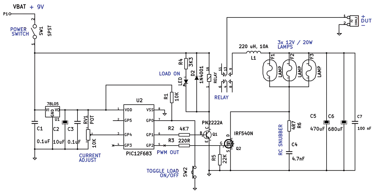
FIGURE 5. Schematic diagram.
The corresponding schematic for my final circuit is shown in Figure 5. I used three incandescent light bulbs of the type you find in car brake lights and connected them in parallel (more on lamp selection later). These light bulbs can handle large currents and are designed for voltages around 12V, though I was able to drive them with voltages up to 20V without problems.
The power MOSFET I chose for this circuit (Q2) is the IRF540N which has very low ON resistance (about 44 mΩ), so it dissipates little power when turned ON. The IRF540N has a gate threshold voltage below 4V, so it can be driven directly by the 5V microcontroller with only a series resistor (R3) to limit the input current and edge rate. Pull-down resistor R5 ensures the MOSFET is OFF by default.
The microcontroller’s GP1 output controls a 2N2222 transistor (Q1) that, in turn, activates the relay coil connected to the 9V supply. It also turns ON an LED to signal the user that the load is connected. Diode D2 protects the transistor from inductive ‘kick-back’ voltages.
I used three different capacitors in parallel (C5, C6, and C7) in an effort to reduce the Equivalent Series Resistance (ESR) over a wide frequency range. Low ESR is important in this application for effective low-pass filtering and to reduce the heat dissipated in the electrolytic capacitors themselves (which could lead to failures over time).
The RC snubber circuit formed by R6 and C4 reduces the voltage spikes and noise generated when the MOSFET switches ON and OFF (see the sidebar, RC Snubber).
RC Snubber
A common issue when quickly switching a power MOSFET is that it can result in significant noise and ringing when the MOSFET turns ON/OFF abruptly. This is caused by the parasitic inductance and capacitance in the circuit which forms an RLC tank circuit that is — in effect — responding to a ‘step’ input. To minimize the resulting VDS (Drain to Source) voltage spikes and oscillations, one can place an RC snubber across the MOSFET Drain and Source pins.
Figure A shows the VDS transient voltage spike I measured with and without the RC snubber formed by R6 and C4. While there is still some room for optimization here, you can see that the voltage spike peak is significantly reduced and so is the oscillatory behavior. RC snubbers protect the MOSFET from over-voltage and reduce noise that could otherwise couple to sensitive circuits connected to this load.
For more information, please refer to Reference [2].
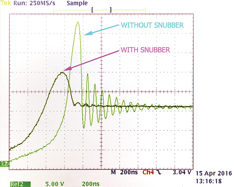
FIGURE A.
Incandescent Light Bulb Selection
In this project, I reused automotive brake lights that I already had in my parts bins. However, for those who don’t already have them handy, these light bulbs are easy to find in any automotive parts store. Light bulbs for automotive applications are physically small (relative to the power they can handle), and are also relatively inexpensive. Any 12V, 20W, to 50W bulbs should be adequate. The choice rests mostly on the maximum current you need to draw for the supply voltages you plan to test. The higher the light bulb power rating, the higher the current you will be able to draw in your load.
For example, a single 20W 12V bulb would nominally draw about 20/12 = 1.67A at 12V. This circuit allows you to draw less current than this by adjusting the potentiometer, but not more current. This is why I paralleled three bulbs as I wanted to draw at least 4A maximum at 12V (and I had quite a few unused bulbs available). However, if you don’t routinely need to test supplies with this much current, you may only need one or two bulbs.
You should also be careful not to burn the light bulbs by applying voltages above their rating (above 12V in this case) for extended periods of time while drawing maximum current. You can always place more bulbs in series if this is a requirement for you, or use 24V bulbs instead.
Safety Warning: Incandescent light bulbs get very hot and can burn you! Make sure you don’t touch the bulbs during operation, and include a way to enclose them so the risk of accidental contact is minimized.
Construction
As this is a relatively simple circuit using only through-hole components, I decided to build it using a prototype board (a.k.a., perf board). Figure 6 shows an overhead view of the assembled perf board circuit and highlights the main components. Even though the MOSFET I used doesn’t dissipate the bulk of the power (the light bulbs do), I did equip it with a small heatsink as it can get slightly hot when drawing high currents (in excess of 3A).
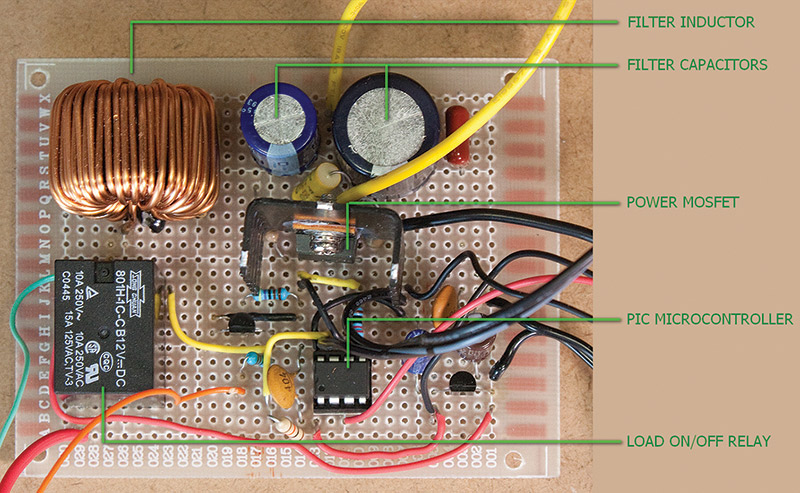
FIGURE 6. Assembled perf board circuit.
Figure 7 shows the underside of the board. Pay close attention to the portions of the circuit where the potentially high load current flows (this is the portion of the circuit represented in the bottom of Figure 3).
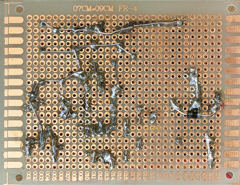
FIGURE 7. Back of the board.
Make sure the wire gauge is thick enough to handle the current through these paths. It also helps to re-enforce (with solder) the high current flow paths as this lowers overall electrical resistance. Also try to keep these connections as short as possible.
Figure 8 shows an early prototype as it was before I committed the circuit to a proper enclosure.
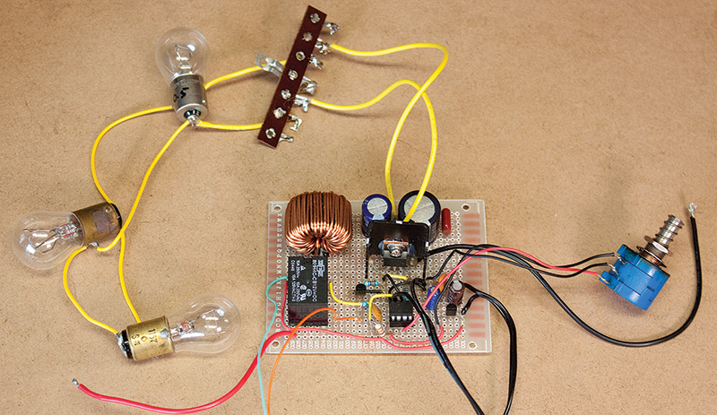
FIGURE 8. An early prototype.
Here, you can see the multi-turns potentiometer and the three lamps connected to the main board.
Figure 9 shows the circuit inside a small plastic enclosure. Notice the 9V battery mounted on the bottom left portion of the box.
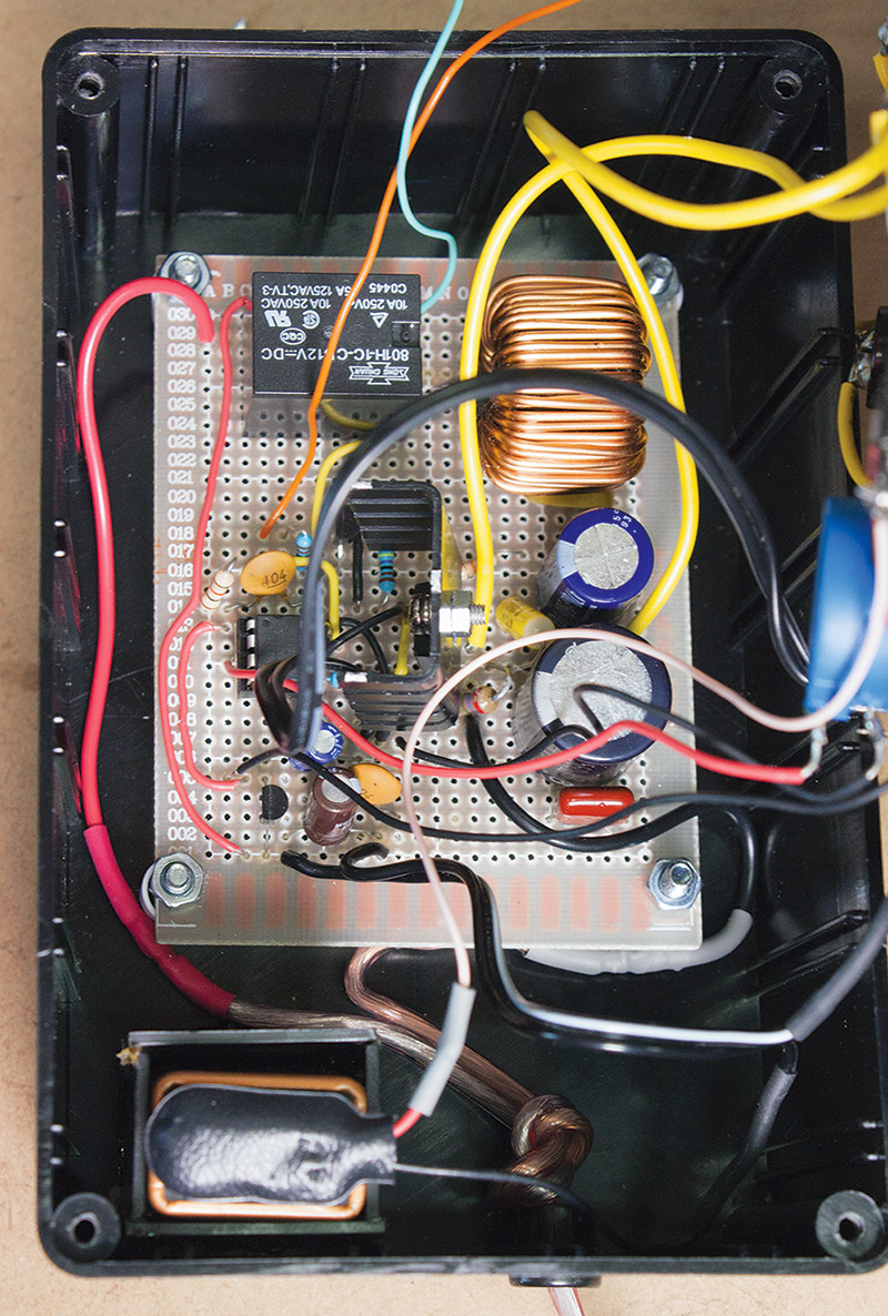
FIGURE 9. Circuit inside a small plastic enclosure.
Figure 10 shows the final product front panel and highlights the main controls and indicators.
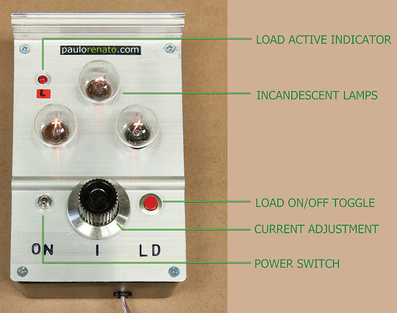
FIGURE 10. Front panel with controls and indicators.
Software
The PIC runs software developed using the the ME Labs PICBASIC PRO© compiler. The complete code is available in the downloads. Both source code and compiled files are available. If you own a PIC programmer and don’t need to make any changes to the code, then you can simply program the PIC using the .hex file without need to recompile the code.
The flowchart in Figure 11 shows the program structure. It starts by defining some constants and performing block-level initializations.
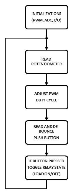
FIGURE 11. Program flowchart.
The internal ADC is connected to the GP4 input and set for 10-bit mode. The PWM is initialized and also set for 10-bit mode so that its resolution is maximized and matches the ADC resolution. As noted earlier, this resolution is important for precise control over a wide range of load currents. Unfortunately, there is a tradeoff between resolution and PWM frequency in this microcontroller (which is not uncommon).
Because of this tradeoff — while I would have preferred using a PWM frequency above 40 kHz as it would have made the LC filtering easier — I ended up setting it to about 8 kHz. With the inductor and capacitor values used, though, this switching rate is high enough for effective filtering.
In the main body of the program, we enter a main loop which starts by reading the ADC voltage (connected to the potentiometer). For the ADC reading, I decided to take eight samples and discard the edge samples to avoid issues with noise. This is done by sorting the eight samples and then averaging only the inner samples (you could call this a “trimmed mean”). The resulting (filtered) value is then used to adjust the PWM duty cycle proportionally to the potentiometer/ADC voltage reading.
Next, the program polls the toggle switch input to detect if it has been pressed. Note that there’s debouncing code executed here to avoid instability. If the switch press is detected, the relay output is toggled and the load turned ON (or OFF).
Results
With the three paralleled light bulbs I used, I was able to draw in excess of 3A at 3.3V and north of 4A with a 5V supply input. This is more than adequate for most of my uses. As I explained under “Incandescent Light Bulb Selection,” the maximum current one can draw with this adjustable load is determined by the light bulb’s power rating and changes in a non-linear fashion with voltage.
For the reader’s reference, I plotted my measured “maximum current versus input voltage” graph in Figure 12.
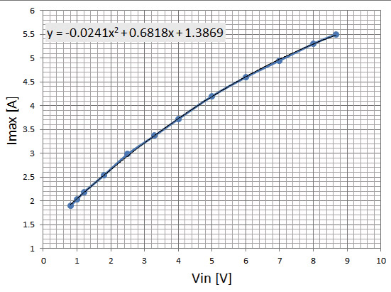
FIGURE 12. Maximum current versus input voltage.
I overlaid a trend line (using Microsoft© Excel) and associated equation that allows the user to estimate the maximum current for voltages other than the ones I measured.
Note that this curve would be different if different light bulbs were used, and represents only the maximum current the load is capable of drawing at each input voltage. Lower currents — from zero up to the maximum — are obtained by simply adjusting the potentiometer.
Conclusions and Future Improvements
While I’m quite satisfied with the current implementation and it has already proven very useful in my hobby, there is always room for improvement in any project. Here are some thoughts for future improvements that the reader may consider:
Gate drive — For high power operation, level shifting the MOSFET gate drive to 9V would result in higher VGS voltage, thus lower on resistance and potentially even less power dissipated in the MOSFET. This should be considered if very high load currents are needed.
PWM frequency — If the reader uses a different microcontroller or even a dedicated PWM circuit, then you might be able to increase the PWM frequency to 40 kHz or higher. This should improve filtering and/or allow you to use a smaller inductor for the same current ripple.
In-rush current limiter — One drawback of incandescent lamps is that their resistance when cold is much lower than in “normal” operation (a factor of 10 times is often mentioned as a rule of thumb). This low ‘cold resistance’ results in a current spike (overshoot) when you first connect the load to a supply under test. While this hasn’t been a significant issue for my purposes, it is something the reader should be aware of as it could (in some cases) trigger over-current protection circuits in the supplies under test.
Adding a small series resistor or even a more complex start-up only current-limiting circuit could improve this situation. For example, you could add another relay controlled by the same microcontroller that keeps a series resistor in-circuit for a few milliseconds following load activation, and then shorts them for steady state operation.
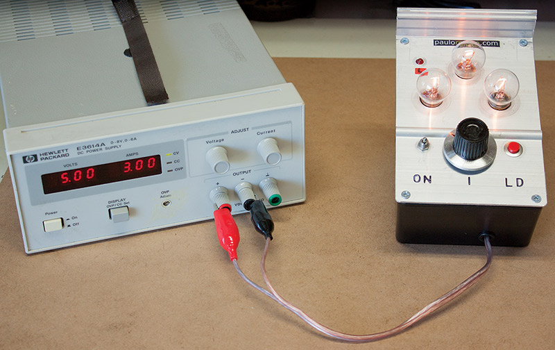
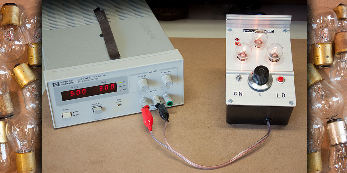
FIGURE 13. Adjustable load in action.
This project has been a rewarding one, not only because it proved very useful on my workbench but also because it allowed me to rescue and re-purpose some of my old incandescent light bulbs. I do enjoy seeing the visual feedback provided by the light glow as current traverses the circuit (see Figure 13).
This is a somewhat unique feature you don’t get with MOSFET based approaches; it’s similar to looking at a good old tube amplifier versus a modern transistor amplifier. Hope you enjoy yours, too. NV
PARTS LIST
| ITEM |
DESCRIPTION |
|
| ACTIVE COMPONENTS |
| U1 |
78L05 5V Linear Regulator |
|
| U2 |
PIC12F683 Microcontroller |
|
| Q2 |
N-Channel Power MOSFET |
|
| Q1 |
2N2222 NPN Transistor |
|
| D2 |
1N4001 Diode |
|
| D1 |
Red LED |
|
| RESISTORS — 1/4W 5% axial carbon film |
| R1 |
10K |
|
| R2 |
4.7K |
|
| R3 |
220R |
|
| R4 |
3.3K |
|
| R5 |
22K |
|
| R6 |
4.7R |
|
| CAPACITORS |
| C1 |
0.1 µF / 100V Ceramic |
|
| C2 |
10 µF / 16V Electrolytic |
|
| C3 |
0.1 µF / 100V Ceramic |
|
| C4 |
4.7 nF / 100V Film |
|
| C5 |
470 µF / 50V Electrolytic |
|
| C6 |
680 µF / 50V Electrolytic |
|
| C7 |
0.1 µF / 100V Ceramic |
|
| MISCELLANEOUS |
| L1 |
Toroid Core Inductor 220 µH, 4A or higher |
|
| RELAY |
SPDT 10A Relay |
|
| RV1 |
10K Multi-turns Potentiometer |
|
| Perf Board |
|
|
| Light Bulbs |
(see text) |
|
References
[1] Building an Adjustable Constant Current Load. Paulo Oliveira.
http://paulorenato.com/index.php/electronics-diy/91-constant-current-load
[2] AN11160 Designing RC snubbers — NXP
www.nxp.com/documents/application_note/AN11160.pdf
Downloads
What’s in the zip?
Source Code