It is often impossible to directly measure the resistance of resistors because of the presence of parallel current paths. Let’s see what we can do about that!
In the resistor bridge circuit in Figure 1, you can see that the center 4.7 kΩ resistor reads just 1 kΩ because of the parallel current paths.
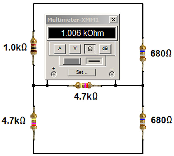
FIGURE 1.
Traditionally, a technician would lift one leg of a resistor to get an accurate resistance measurement. This can be difficult today since surface-mount components are often used. There is a technique taken from automatic test equipment called guarding that uses a controlled voltage source, ammeter, and strategically placed grounds to measure the current going through a single component. With a known source voltage and a current reading, the exact value of an individual resistor can be calculated.
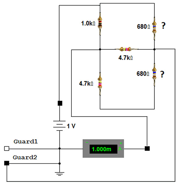
Figure 2 shows how the resistance of the center resistor can be determined using a 1V source and an ammeter.
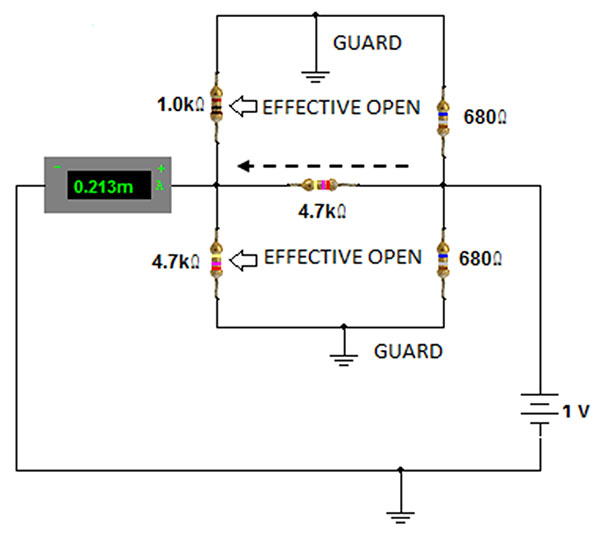
FIGURE 2.
First, place the voltage source on one side of the resistor and the ammeter going to ground on the other side. The difficulty now is the parallel paths around the resistor. To take these parallel paths out of the measurement, place a ground in the center of each path. With a ground on both sides of a resistor, there is no voltage drop across the resistor resulting in an effective open. The precise value of the resistor is calculated by dividing the source voltage by the current. In this case, 1V divided by .213 mA equals 4.7 kΩ.
The position of the source, ammeter, and grounds can be repositioned to measure any of the resistors without the need of breaking the circuit.
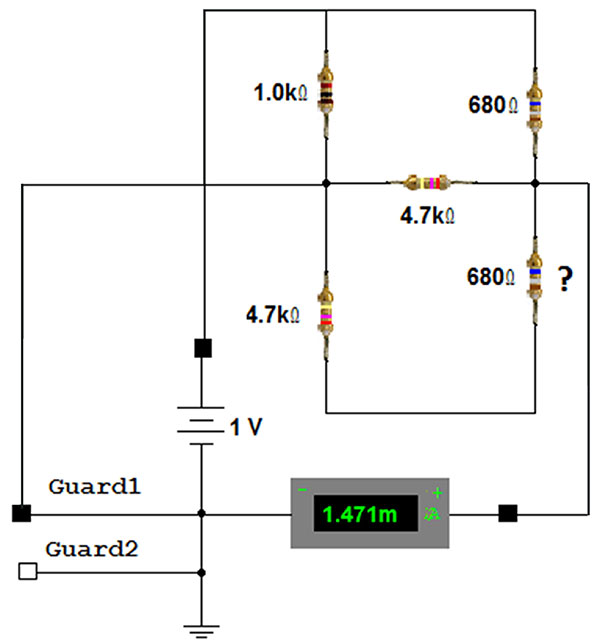
Figure 3 shows how the circuit can be reconfigured to measure the bottom left resistor.
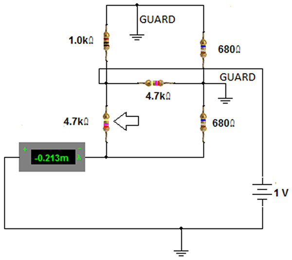
FIGURE 3.
It is important to remember that just because the parallel paths are taken out of the measurement, doesn’t mean that the parallel current paths are eliminated. Care must be taken not to damage any parallel components. It is recommended to use as low a voltage as is possible.
The Challenge
Now, it’s time for a challenge to show how YOU would connect the circuit in Figure 4 to accurately measure the other three resistors.
Find the answers below.
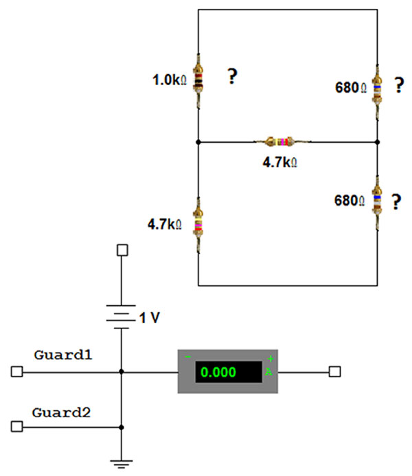
FIGURE 4.
Answers
Answer 1 (top left resistor)
To determine the top left resistor’s value, place the voltage source on the top of the resistor and the ammeter going to ground on the bottom. This will insure a one volt drop across the resistor. Now, place the guard between the top right resistor and the bottom right resistor; this will prevent current flow through the center resistor and open up the single parallel path around the test resistor. The value of the resistor can be determined by dividing the voltage by the measured current.
1 volt/ 1 mA = 1,000Ω
Answer 2 (top right resistor)
To determine the top right resistor’s value, place the voltage source on the top of the resistor and the ammeter going to ground on the bottom. Now, place the guard between the top left resistor and the bottom left resistor; this will open up the single parallel path around the test resistor. The value of the resistor can be determined by dividing the voltage by the measured current.
1 volt/ 1.471 mA = 680Ω
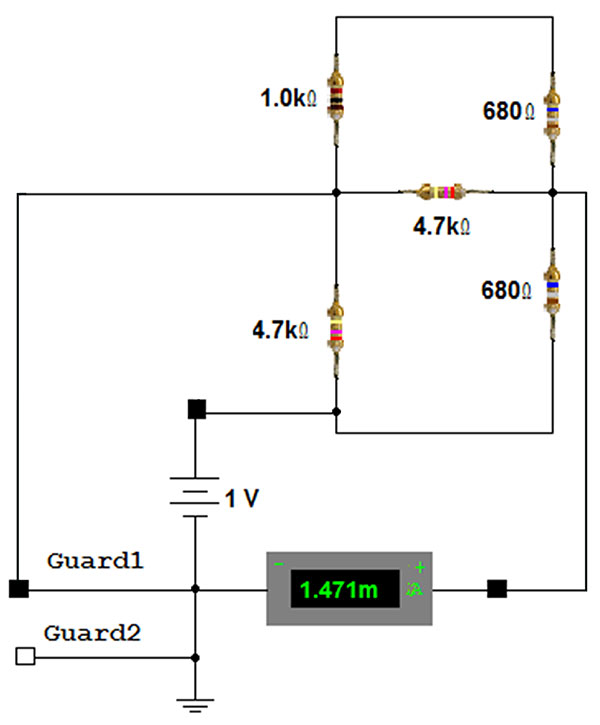
Answer 3 (bottom right resistor)
To determine the bottom right resistor’s value, place the voltage source on the top of the resistor and the ammeter going to ground on the bottom. Now, place the guard between the top left resistor and the bottom left resistor; this will open up the single parallel path around the test resistor. The value of the resistor can be determined by dividing the voltage by the measured current.
1 volt/ 1.47 mA = 680Ω
So, did you pass? NV