Radio frequency identification (RFID) devices are ubiquitous in electronic controlled-access systems. Although they’re considered to be secure devices, they’re a little too expensive for hobby applications. So, here’s a design for an electronic lock using an inductance coil.
Introduction
People have been securing their homes and possessions with lock and key devices for millennia. Our electronic age has seen the appearance of non-mechanical locks, such as the wireless entry systems for automobiles. Many of us have employer-issued access cards that serve as door keys, and they also serve as a way to monitor who opens a certain door, and when that happened.
The early access cards used a magnetic stripe. Later, more reliable cards used magnetized wires embedded in the plastic. Presently, RFID devices are used in most access cards. RFID devices are small computer chips that harvest operating power from an electromagnetic field generated by the card reader. They then use this power to transmit a coded signal, sometimes in response to a “challenge” signal. These RFID chips possess a lot of computing power, and high level cryptographic protocols can be employed to make for very secure access. The access cards themselves can be quite inexpensive, but an RFID reader is somewhat costly. In a typical access system, this cost is shared among many access cards, so the cost is warranted for the security provided.
If you’re interested in implementing an electronic key for a hobby project, RFID is definitely too costly. Wireless access systems are a little less expensive, but not by much. This article presents a simple and inexpensive electronic key system. It has the possible advantage that the key can be made to actually look like a key.
Another Approach
If we go back to basics, nothing in electronics is more simple than the three principal electrical circuit elements. These are the resistor, the capacitor, and the inductor. There’s a possible fourth circuit element — the memristor — defined by a symmetry in the equations. Figure 1 shows these four circuit elements.
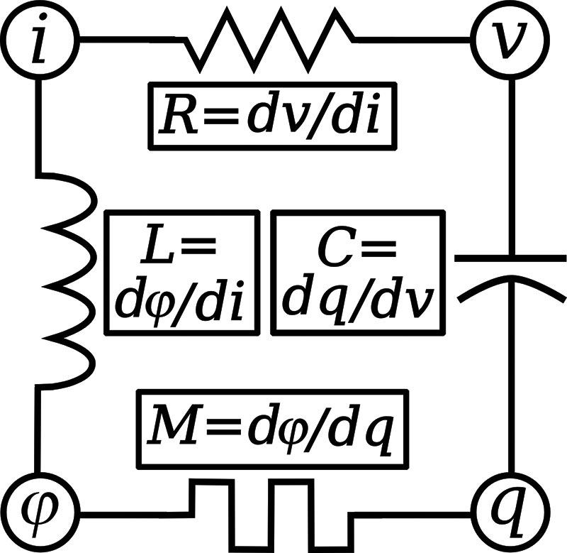
FIGURE 1. The four fundamental electrical circuit elements: the resistor, capacitor, inductor, and memristor. The resistance (R), capacitance (C), inductance (L), and memristance (M) are defined by derivatives of the voltage (v), current (I), charge (q), and magnetic flux (φ).
It would be possible to build an electronic lock in which the key is a particular value of resistance, capacitance, inductance, or memristance. In that case, you would make contact with the key element by two electric terminals to sense the particular value.
It’s a lot easier when the key can be read without making electrical contact. Our electronic key is based on an inductance value; but, instead of connecting an inductance, we modify an internal inductance by inserting a ferrite core. The ferrite — which is embedded in the key — increases the inductance by a fixed amount, and the presence of this particular inductance sends an “unlock” signal to a device.
Figure 2 shows an example of an inductance coil and mating key. There’s an inch long inductance coil, wound from about 125 turns of insulated wire in three layers, on a 1/4 inch inside diameter cylindrical coil form. The wire used here is 38 AWG plastic-insulated “wire-wrap” copper wire, but enamel-coated “magnet” wire could have been used instead. The key is a mating plastic tube in which small ferrite cores of the sort used to make simple radio frequency (RF) chokes are glued inside. Inserting the key into the inductor changes the inductance by a particular value. A greater or lesser number of ferrite core pieces can be used to make different key values.
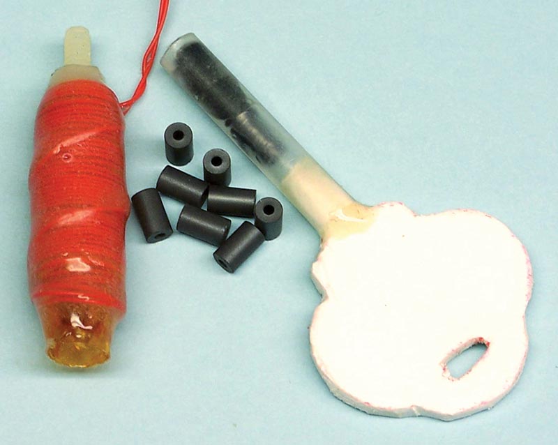
FIGURE 2. An inductance coil, mating key, and some ferrite core pieces used to make the key. The coil was wound with AWG 38 wire-wrap copper wire, but enameled copper magnet wire could be used.
Basic Inductance Lock and Key Circuit
The easiest way to read an inductance is by making it part of an inductance-capacitance resonator in an oscillator circuit. The frequency of this oscillator can be compared to that of a reference oscillator, and an unlock signal can be generated when the frequencies match within a predetermined range.
One way to compare frequency signals is to use a mixer circuit. A mixer will produce the sum of its two input frequencies, or their difference. When the frequencies are very close, the difference signal will fall into the audio frequency band where it can be selected by a low pass filter, and then rectified to obtain a control signal. A block diagram of this process is shown in Figure 3.
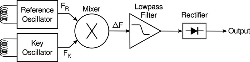
FIGURE 3. Block diagram of an electronic key system using two oscillators. The frequency of the reference oscillator is adjusted to put the frequency difference between it and the key oscillator into the bandpass of the filter.
A practical implementation of this circuit is shown in the schematic diagrams in Figures 4 and 5.
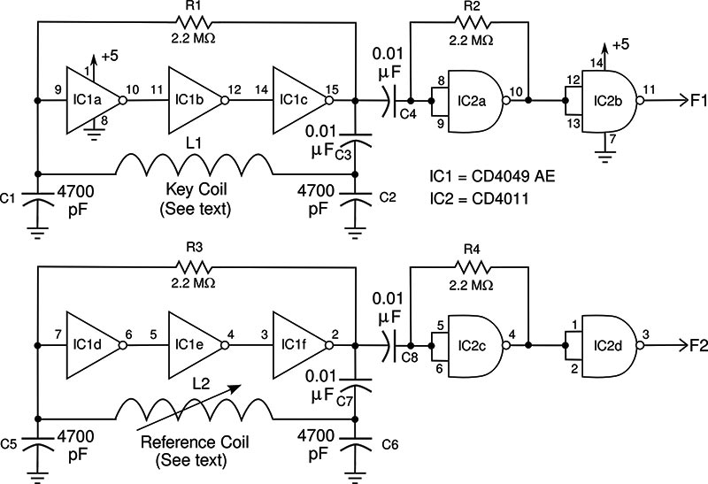
FIGURE 4. Schematic diagram of the oscillator portion of the electronic key system.
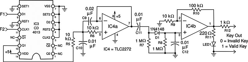
FIGURE 5. Schematic diagram of the mixer, low pass filter, and rectifier of the electronic key.
As can be seen from Figure 4, it’s possible to use resistors to bias inverters of a CMOS logic circuit to function as amplifiers in an oscillator. The gain of each individual inverter of the CD4049 is only 30, but cascading three inverters gives you an amplifier with a gain of more than 10,000. This is sufficient to drive the LC resonator into oscillation. The additional stages of the CD4011 buffer the oscillator signal.
A wide variety of coils can serve as the inductance. I’ve used anywhere from 100-250 turns of AWG 38 wire in 2-4 layers, wound to an inch length on a coil form with a 1/4 inch inside diameter. These coils oscillate in the range of about 400-1,000 kHz, so you could actually verify operation of most of these by holding an AM radio nearby. The coil shown in Figure 2 has three layers of 35 turns each.
Using that coil, the oscillator had a frequency of 516 kHz when no key was inserted. Inserting a key containing two ferrite cores decreased this to 387 kHz. A key with three ferrite cores caused oscillation at 286 kHz.
The easiest way to make the reference coil is to wind a coil identical to the key coil, and then attach an assembly that allows a controlled insertion of a tube filled with ferrite. In my case, I used a nylon bolt and nut for this purpose since conductive pieces (such as metal) are not allowed.
The schematic diagram in Figure 5 shows the mixer, low pass filter, and rectifier. The mixer uses a CD4013 “D” type flip-flop as a digital mixer. A precaution observed in using CMOS logic is to ground unused inputs since these might float “high” and draw excessive device current. Such digital mixers do produce a difference signal, but they also respond to harmonics of the input frequencies. This “feature” doesn’t matter in our circuit.
The low pass filter is a two-pole Butterworth with a corner frequency of about 2 kHz. This circuit is characterized by one capacitor (C9) being twice as large as the other (C10). The easiest way to implement this is to just buy three capacitors of the lower value, and make the higher value using two parallel capacitors. This makes a lot of sense in this circuit since there are many 0.01 µF capacitors.
The choice of operational amplifier is not critical. You can use any “rail-to-rail” type operable on a five volt supply. Rectification is accomplished with diode D1, the rectified signal is filtered by C12, and then amplified. There’s a logic level output you can use to drive other circuitry; for example, an optically-isolated solid-state relay, or just a power transistor for driving a solenoid.
The circuit is calibrated by inserting the key and then adjusting the reference inductor to give a slightly lower frequency within the passband of the low pass filter. This setting is aided by the LED, which lights when the frequency condition is matched. Note that setting the frequencies exactly equal is not desirable since the low difference frequency will not filter well.
As shown in Figure 6, the mixer responds to frequency differences on both sides of an exact frequency match. That means you can also set the reference oscillator for a higher frequency than the key oscillator. This will work, too, but there will be a blip in the output as the key is inserted or extracted as it passes through the zero point.
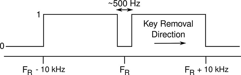
FIGURE 6. Performance of the mixer circuit. The LED will light when the key oscillator frequency is within a range of the reference oscillator frequency.
The circuit shouldn’t generate any radio frequency interference; but, as a precaution, it should be built inside a grounded metal enclosure. You can ensure that radio frequency interference is not being emitted by placing an AM radio a few feet away and scanning the band. As mentioned earlier, the coils will resonate at AM radio frequencies. Or, if they resonate below, their second harmonic signal will be in the AM radio band.
Simplify with a Microcontroller
This circuit functions as expected, and it’s built from commonly available components. I had all the parts in my shop drawers, and the CMOS ICs were left over from some very old projects. The only problem the circuit has is that a lot of components are required for such a simple task. One way to decrease component count in a circuit is to throw some software into the solution. For that reason, I’ve designed another electronic lock system using a microcontroller. The schematic for this is shown in Figure 7.
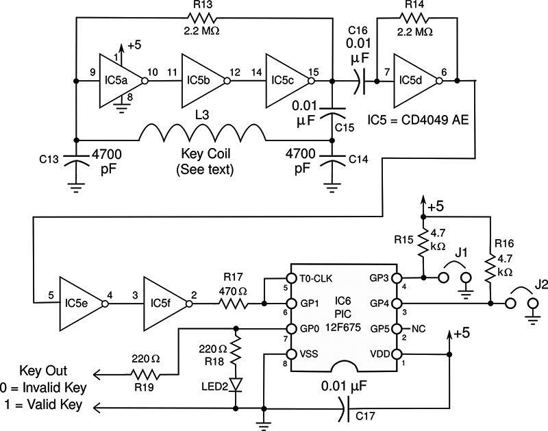
FIGURE 7. Schematic diagram of the microcontroller version of the electronic key system.
As you can see in Figure 7, we have the same sort of oscillator as in the first circuit, but there’s only one. Its output goes to the microcontroller, which acts as a frequency counter. The frequency is compared against stored values that correspond to the presence of up to three different keys.
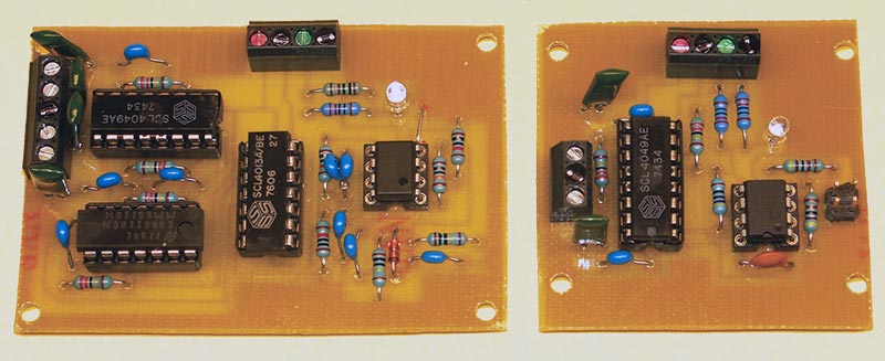
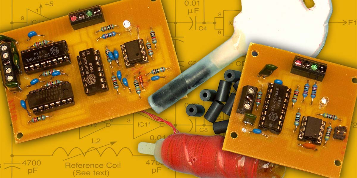
FIGURE 8. Photos of the circuit boards of the two versions of the electronic key circuit. The microcontroller version (right) uses fewer components, but it does require a programmed microcontroller chip.
To measure the frequency, we merely count the number of pulses that occur in a set time interval. To do this, we need a timer and a counter. The PIC microcontroller has a 16-bit timer, Timer 1, that allows us to set a fairly accurate period using the internal clock oscillator. In our case, we count pulses in 40 millisecond intervals.
Getting an accurate pulse count presents a small problem since the remaining counter is only eight bits, which would allow reading the frequency to one part in 256. We’re saved by a trick — published on the microcontroller manufacturer’s website — that allows 16-bit resolution by some software trickery involving resistor R17 and a spare microcontroller pin.
Since the counter input passes through an eight-bit prescaler, we use the spare pin to step additional pulses into the prescaler. By counting how many pulses are needed to increment the counter, we can calculate the prescaler count, thereby adding its eight-bit resolution to our existing eight-bit counter. In this way, we get 16-bit resolution of the frequency.
The microcontroller is calibrated to up to three different keys using the jumpers, J1 and J2. In normal operation, J1 and J2 are left open. If one or both jumpers is sensed when power is supplied and the microcontroller program reboots, the software stores whatever frequency value it finds. Having a key present when that happens stores the key value for comparison in normal operation.
After the key value is stored, the program halts. You then remove the jumper (or jumpers) and the circuit will function as a lock matched to that key on subsequent power-ups. As shown in Table 1, up to three keys can be stored, so one of these keys can be a “master” key. In this sense, the microcontroller circuit has another advantage other than just needing fewer components.
| State |
J1 |
J2 |
| Operate |
OUT |
OUT |
| Key 1 |
IN |
OUT |
| Key 2 |
OUT |
IN |
| Key 3 |
IN |
IN |
TABLE 1.
Software
The source code — written in PIC BASIC PRO — is available in the downloads, along with hex files for using the code without a compiler. The software also serves as a tutorial on how to use a PIC timer as a frequency counter. You still need to program the microcontroller, but there are quite a few circuits for inexpensive programmers on the Internet, and also a few inexpensive programmers, themselves.
Caveats and Conclusion
A few caveats are in order. This system is about as secure as the simple lock and key devices in furniture and children’s toys. It’s not as secure as most RFID locks, and I certainly wouldn’t secure my house with one. It would be good for locking-out TVs and game systems during homework time, or as a lock for a child’s lock-box or diary.
Of course, as with any electronic lock system, you should have an alternative means of opening your lock in the event of a circuit or power failure. The paper clip inserted in a hole that once was needed for computer optical discs is one possibility.
Also, you needn’t be limited to the key shape presented. You can have a card instead of a key, with a flat coil to accept the card and some ferrite powder glued between sheets of plastic. If you decide to crush ferrite cores to make a powder, remember to wear safety glasses! Wrapping them in paper and crushing in a vice is a typical approach. NV
Parts List
| Item |
Description |
Item |
Description |
| Circuit with Mixer |
Circuit with Microcontroller |
| R1-R4 |
2.2 megaohm |
R13-R14 |
2.2 megaohm |
| R5-R6, R9 |
10K ohm |
R15-R16 |
4.7K ohm |
| R7-R8 |
1 megaohm |
R17 |
470 ohm |
| R10 |
100K ohm |
R18-R19 |
220 ohm |
| R11 |
220 ohm |
|
|
| R12 |
1K ohm |
C13-C14 |
4700 pF NPO |
| |
|
C15-C17 |
0.01 µF |
| C1-C2, C5-C6 |
4700 pF NPO |
|
|
| C3-C8, C10-C12 |
0.01 µF |
L3 |
Key Coil (Note 2) |
| C9 |
0.02 µF (Note 1) |
|
|
| |
|
IC5 |
CD4049 AE |
| D1 |
1N4148 |
IC6 |
PIC12F675 |
| |
|
|
|
| L1 |
Key Coil (Note 2) |
LED2 |
Red LED |
| L2 |
Reference Coil (Note 2) |
|
|
| |
|
J1 |
Jumper |
| IC1 |
CD4049 AE |
J2 |
Jumper |
| IC2 |
CD4011 |
|
|
| IC3 |
CD4013 |
|
|
| IC4 |
TLC2272 (Note 3) |
|
|
| |
| LED1 |
Red LED |
|
|
| |
Misc
Five volt Power Supply
IC Sockets
Terminals
Hardware
PCB (Patterns are available at the article link) |
Notes:
(1) Can be a parallel combination of two 0.01 µF capacitors.
(2) See text.
(3) Most five volt rail-to-rail operational amplifiers will work. You need two, or a dual chip. |
The source code for the circuits, and hex files for burning the object code directly without a need for a compiler, are available in the downloads below, as are the CAD files for the printed circuit board, and other useful files.
References
The datasheet for the PIC 16F675 is available from Microchip
ww1.microchip.com/downloads/en/devicedoc/41190c.pdf
Stan D’Souza, “Frequency Counter Using PIC16C5X ,” Microchip Technology, Inc., Application Note AN592
ww1.microchip.com/downloads/en/AppNotes/00592d.pdf
PIC BASIC PRO is available from M.E. Labs, Inc.
2845 Ore Mill Road, Ste. 4, Colorado Springs, CO 80904
phone 719-520-5323; www.melabs.com.
Author Bio
Dev Gualtieri received his Ph.D. in Solid State Science and Technology from Syracuse University in 1974. He had a 30 year career in research and technology at a major aerospace company and is now retired. Dr. Gualtieri writes a science and technology blog at www.tikalon.com/blog/blog.php. He is the author of two science fiction novels, and books about science and mathematics. See www.tikalonpress.com for details.
Downloads
What’s in the zip?
Source Code
Hex Files
PCB Files
PCB Images