Building digital clocks is not the sexiest of DIY projects, yet many people do so each year. People build these clocks in a wide variety of shapes and sizes, including the weird one I designed and wrote about in the March 2014 issue called, “A Unique LED Clock.” Most homebrewed digital clocks use an Arduino or other microcontroller coupled to a real time clock (RTC) chip that provides the time keeping machinery and (in some cases) battery backup facilities. It is up to the user to set the clock to the correct time. If good quality components are used in the clock, time keeping accuracy can be pretty good. However, unless the RTC chip's oscillator is temperature controlled, accuracy will drift over time forcing the user to perform periodic corrections. Also, some RTC chips don't handle daylight saving time (DST), so it is up to the user to reset their clocks twice a year in affected areas.
To overcome the problems with manual time, date setting, and time drift, many so called “atomic clocks” or “radio controlled clocks” have appeared on the market. They come in just about every conceivable shape and size. These clocks listen for WWV radio transmissions from Fort Collins, CO, and synchronize their time keeping mechanisms to the atomic clock reference used for these transmissions. This helps guarantee their time keeping accuracy. Clocks like these typically require the user to select their time zone, but other than that do not offer any controls for manually setting the time.
The clock mechanisms in PCs work differently. PCs usually sync their RTC using an Internet standard called Network Time Protocol, or NTP.
According to Wikipedia:
NTP is a networking protocol for clock synchronization between computer systems over packet-switched, variable-latency data networks.
NTP is intended to synchronize all participating computers to within a few milliseconds of Coordinated Universal Time (UTC).
NTP can usually maintain time to within tens of milliseconds over the public Internet, and can achieve better than one millisecond accuracy in local area networks under ideal conditions.
Basing a digital clock design on NTP requires access to the Internet which can be expensive to implement, but allows for a very simple clock design for a couple of reasons. First, no battery backup circuitry is required to maintain the time setting. If clock power is lost, the connection to the Internet will automatically be reestablished once power is restored; the clock will automatically set itself to the correct time. Second, no controls for manually setting the time are typically necessary because time and date settings are automatic.
The ESP8266 family of devices makes inexpensive access to the Internet a non-issue, so it’s natural to use these devices in an NTP clock. Current readers of Nuts & Volts may remember my two previous articles about using the amazing ESP8266 devices:
- “Meet the ESP8266: A Tiny, Wi-Fi Enabled, Arduino Compatible Microcontroller” in the October 2015 issue; and
- “Thinking of You” in the November 2015 magazine.
To refresh your memory, all members of the ESP8266 device family share some basic characteristics, including:
- 802.11 b/g/n
- Wi-Fi Direct (P2P), soft-AP
- Built-in TCP/IP protocol stack
- 802.11b mode + 19.5 dBm output power
- Built-in temperature sensor
- Supports antenna diversity
- Off leakage current is less than 10 µA
- Built-in low power 32-bit CPU which can double as an application processor
- SDIO 2.0, SPI, UART, ADC, EEPROM
- Standby power consumption of less than 1.0 mW (DTIM3)
In other words, the ESP8266 family of modules features low power consumption, high RF power output, and are capable of supporting all of the current 802.11 standards required for Wi-Fi connectivity. In addition, they support many industry standard hardware interfaces and can function as the application processor in many designs as they do in this one. The ESP8266 is a 3.3 VDC part.
Two things make using these parts even sweeter. First, many ESP8266 modules can be purchased for under $10 in single unit quantities. Second, these modules can be programmed in the Arduino IDE (integrated development environment), so Arduino developers don’t have to learn yet another programming system to use them.
In this article, I present the design and implementation of a very simple NTP digital clock based on the ESP8266 that drives a small LCD display. In actuality, I used an ESP8266 variant called a NodeMCU LUA Amica as it has lots of digital I/O pins available, making interfacing to the display trivial. This clock has a single pushbutton switch that — if configured for daylight saving time operation (more on this later) — allows the user to put the clock into and take the clock out of DST mode.
Designing this digital clock allowed me to experiment with aspects of the ESP8266 that I had not used before, including the hardware SPI interface used to run the LCD display and the onboard EEPROM for storage and retrieval of the DST state indicator.
Hardware
The hardware Parts List shows the items required to build one of these NTP clocks and where to get them. As you’ll see, there isn’t much to it. Figure 1 shows a Fritzing connection diagram/schematic for the NTP clock.
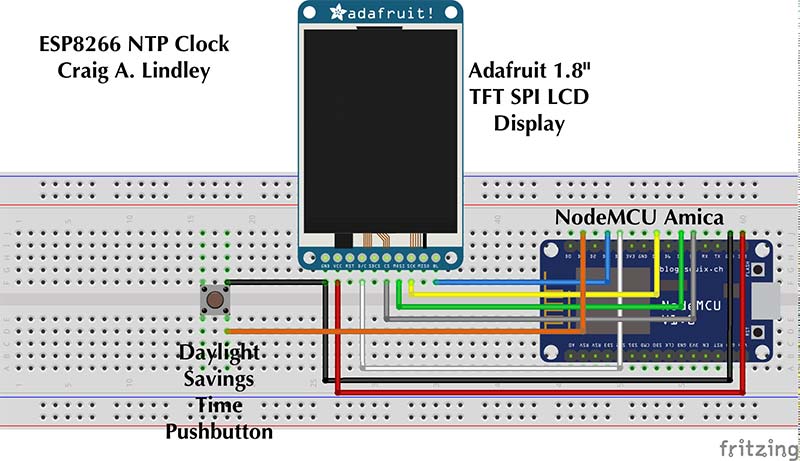
FIGURE 1. ESP8266 NTP clock wiring diagram/schematic.
Figure 2 shows the design wired up and working on a breadboard. NOTE: There isn’t a wire color correlation between Figures 1 and 2. As shown, the clock is powered via a USB cable and a USB power supply module.
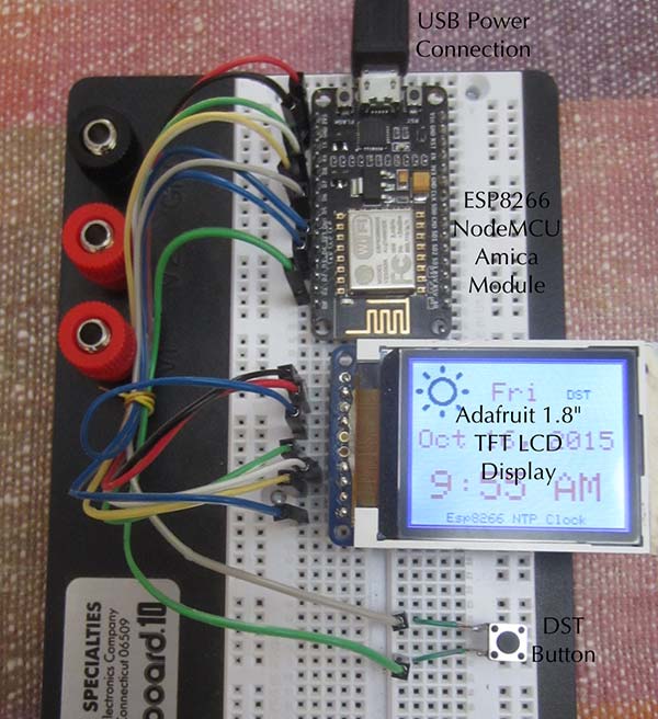
FIGURE 2. The ESP8266 NTP clock breadboard.
The wire by wire connections are shown in Table 1 (in case they’re not be clear from the Fritzing diagram). The GPIO designations are also shown in Table 1. This is how these digital I/O lines are referred to in the Arduino code.
| NodeMCU Amica Pin |
Adafruit 1.8” Display
Connection |
DST Pushbutton
SPST Switch |
| D1 (GPIO 5) |
|
SW1 |
| D3 (GPIO 0) |
LITE |
|
| D4 (GPIO 2) |
D/C |
|
| D5 |
SCK |
|
| D7 |
MOSI |
|
| D8 (GPIO 15) |
TFT_CS |
|
| 3V3 |
VCC |
|
| GND |
GND |
SW2 |
TABLE 1.
The Adafruit LCD display has a microSD memory card connector and interface which can be used with the ESP8266; these were not needed for this particular project.
Software
The software for the ESP8266 NTP clock was developed using the Arduino IDE. Refer to my previous articles or the Resources section for how to set up the Arduino IDE on your computer for targeting ESP8266 type devices. Make sure to select “NodeMCU 1.0 (ESP-12E Module)” as the board type in the Tools menu.
The ESP8266 NTP clock software is available at the article link; it’s called Lindley_ESP8266NTPClock.zip. To use the software, unzip it and copy/move the ESP8266NTPClock directory from the zip file into your Arduino directory.
Whereas the hardware for this clock borders on the trivial, the software/firmware for the clock is a bit more involved and complex. The seven files which make up the code are described in Table 2.
| File |
Description |
| ESP8266NTPClock.ino |
Main program. Initializes the hardware, logs into the local Wi-Fi network, and then installs the NTP code as the time provider. It then manages the update of the clock on the display. |
| ESP8266_ST7735.cpp |
LCD driver code specific to the Adafruit 1.8” (black tab) display utilizing the hardware SPI interface of the ESP8266. |
| ESP8266_ST7735.h |
Header file for the LCD driver code above. |
| Icons.h |
Data for the Wi-Fi, sun, and moon icons. Data is in xbm format. |
| NTP.h |
Functions for sending UDP packets to NTP servers, and retrieving the GMT time and converting it to local time. |
| TextGraphicsFunctions.h |
Misc functions for formatting the time data for display on the LCD. |
| Misc.h |
Code for reading and writing the ESP8266’s EEPROM. |
TABLE 2.
The ESP8266_ST7735 LCD driver code was adapted from the Adafruit ST7735 library to use the hardware SPI interface on the ESP8266. If you want to use a different LCD display, you will have to find/develop an appropriate driver yourself.
In addition to the files above, the Arduino libraries in Table 3 are also required.
The version of these libraries I used to develop the NTP clock is included in the zip file for this article. Remember, libraries must be installed in the arduino/libraries directory on your development computer and the Arduino IDE must be restarted to recognize them.
Most of the code that makes up the NTP clock is straightforward and will be easy to understand. The NTP code in the file NTP.h is more complex, however. To retrieve the time, one must get an IP address of a time server from the pool of time.nist.gov servers using the hostByName function as shown in the following code. If you were to monitor the timeServerIP address during the operation of the clock, you would see that the time requests rotate in a round robin fashion between the servers in the time.nist.gov pool:
// Get a server from the pool<br />
WiFi.hostByName(“time.nist.gov”, timeServerIP);
Once you identify a server to make a request to, you must create a UDP packet configured with the proper values and then send it the packet. See https://tools.ietf.org/html/rfc5905#section-7.3 for an explanation of the fields in the UDP request packet. The following sendNTPPacket function does this:
// Send an NTP request to the time server at the given address<br />
unsigned long sendNTPpacket(IPAddress& address) {
  // Set all bytes in the buffer to 0<br />
  memset(packetBuffer, 0, NTP_PACKET_SIZE);
  // Initialize values needed to form NTP request<br />
  packetBuffer[0] = 0b11100011; // LI, Version, Mode<br />
  packetBuffer[1] = 0;          // Stratum, or type of clock<br />
  packetBuffer[2] = 6;         // Polling Interval<br />
  packetBuffer[3] = 0xEC;      // Peer Clock Precision<br />
  // 8 bytes of zero for Root Delay & Root Dispersion<br />
  packetBuffer[12]  = 49;<br />
  packetBuffer[13]  = 0x4E;<br />
  packetBuffer[14]  = 49;<br />
  packetBuffer[15]  = 52;
  // All NTP fields have been given values, now<br />
  // you can send a packet requesting a timestamp:<br />
  udp.beginPacket(address, 123); // NTP requests are to port 123<br />
  udp.write(packetBuffer, NTP_PACKET_SIZE);<br />
  udp.endPacket();<br />
}
Once the UDP packet is sent, you wait for a response; in that response will be a time stamp (the four bytes starting at the 40th byte of the response) indicating the time the packet was sent. The units of this time stamp are seconds (since 1900) and it is a very large number. This value gets converted to Unix time (which is seconds since January 1, 1970) by the subtraction of the number of seconds between 1900 and 1970. This number is then further modified via time zone correction. This corrected value is used by the Time library, and converted to the current time and date displayed by this clock. The getNTPTime function pulls this all together:
// NTP Time Provider Code<br />
time_t getNTPTime() {
int attempts = 10;
  // Try multiple attempts to return the NTP time<br />
  while (attempts—) {
    // Get a server from the pool<br />
    WiFi.hostByName(ntpServerName,<br />
    timeServerIP);<br />
    Serial.print(“Time server IP address: “);<br />
    Serial.println(timeServerIP);
while (udp.parsePacket() > 0); // Discard any previously received packets
    Serial.println(“Transmitted NTP Request”);<br />
    sendNTPpacket(timeServerIP);
    uint32_t beginWait = millis();<br />
    while (millis() - beginWait < 1500) {<br />
      int size = udp.parsePacket();<br />
      if (size >= NTP_PACKET_SIZE) {<br />
        Serial.println(“Received NTP<br />
        Response”);<br />
        udp.read(packetBuffer, NTP_PACKET_SIZE); // Read packet into the buffer<br />
        unsigned long secsSince1900;
        // Convert four bytes starting at location 40 to a long integer<br />
        secsSince1900 =  (unsigned long)<br />
        packetBuffer[40] << 24;<br />
        secsSince1900 |= (unsigned long)<br />
        packetBuffer[41] << 16;<br />
        secsSince1900 |= (unsigned long)<br />
        packetBuffer[42] << 8;<br />
        secsSince1900 |= (unsigned long)<br />
        packetBuffer[43];
Serial.println(“Got the time”);
        return secsSince1900 - 2208988800UL +<br />
        realTimeZoneOffset * SECS_PER_HOUR;<br />
      }<br />
      delay(10);<br />
    }<br />
    Serial.println(“Retrying NTP request”);<br />
    delay(4000);<br />
  }<br />
  Serial.println(“No NTP Response”);<br />
  return 0;<br />
}
User Configuration of the NTP Clock Software
The NTP clock’s software must be configured before the clock will work correctly. All user configuration items are found in the ESP8266NTPClock.ino file. Please locate the following code in that file:
// **********************************************<br />
// Start of user configuration items<br />
// **********************************************
// Set your WiFi login credentials<br />
#define WIFI_SSID “xxxxxxxx”<br />
#define WIFI_PASS “xxxxxxxxxxxxx”
#define TIMEZONE_OFFSET -7    // Set your timezone offset (-7 is mountain time)<br />
#define USE_DST         true  // Set to false to disable DST mode<br />
#define HOUR_FORMAT_12  true  // Set to false for 24 hour time mode
// **********************************************<br />
// End of user configuration items<br />
// **********************************************
First — and most importantly — you must modify the code with the SSID and password of your Wi-Fi network. Otherwise, the clock won’t be able to access the Internet, and by extension the NTP servers that provide the time. Next, you must set the correct time zone offset for your location. Time zone offsets can be found at https://en.wikipedia.org/wiki/List_of_UTC_time_offsets.
You must then decide if your clock will use DST or not, and whether it will operate in 12 or 24 hour format. USE_DST must be set true if your clock will use daylight saving time, whether or not DST is currently in effect. Set HOUR_FORMAT_12 true to run your clock in 12 hour format; otherwise, it will operate in the 24 hour time format.
The code can be compiled and uploaded to the NodeMCU device once the configuration data is set and all of the required libraries have been installed in the Arduino environment.
NTP Clock Operation
The clock should start immediately once the software is uploaded. Figure 3 shows the clock’s display while a connection is being made to the local Wi-Fi network.
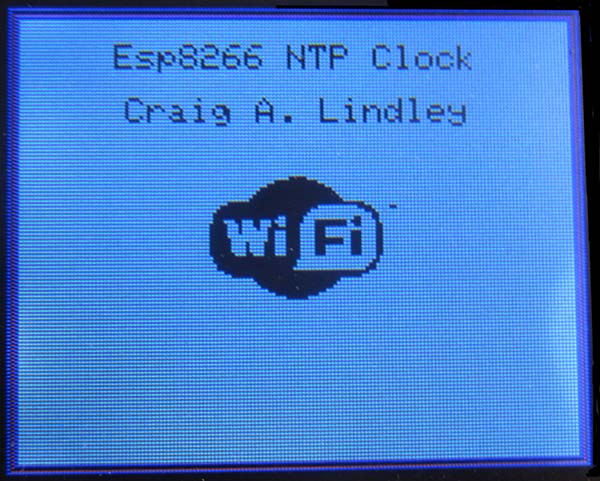
FIGURE 3. Initial Wi-Fi connection display.
If this screen doesn’t change to the clock display of Figure 4, it means there were problems logging into the Wi-Fi network. If this is the case, go back and verify the WIFI_SSID and WIFI_PASS entries in the code, and that the Wi-Fi network is working.
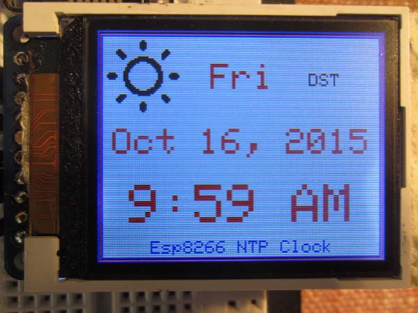
FIGURE 4. Typical clock display. Note: Daylight saving time (DST) mode is on; when the sun icon is displayed, it is daytime.
As mentioned, the Wi-Fi login display should change to the clock display in Figure 4 once a Wi-Fi connection is established. If the clock is not configured for DST mode, you are done. The clock should run as long as power is applied, and it will sync up its time to an NTP time server every five minutes. This makes the clock extremely accurate.
If the clock is configured for DST operation (USE_DST is true), it is up to the user to put the clock in DST mode if DST is currently in effect (mid April through November in the US). The clock doesn’t default to DST mode, so the user must push the DST button until the DST string is displayed in the upper right corner of the clock. You’ll notice the displayed time changes when DST mode is engaged. Pressing the DST button again toggles the clock out of DST mode.
The clock will continue to run as long as power is applied. If the Internet connection is dropped, the clock will maintain the time itself. If Wi-Fi goes down but the clock remains powered, the clock will need to be rebooted once the network issue is resolved so NTP time syncing can be restarted. If power is lost to both the clock and the Wi-Fi network, the clock will reboot and wait for the network to come back up, and then will reconnect automatically.
While the clock is operational, the time and date will update once a minute. During the day, a sun icon will be displayed in the upper left corner. The sun icon will be replaced by a moon icon after about 8 p.m. in the evening.
As daylight saving time comes and goes, the user will be required to inform the clock by pressing the DST pushbutton which toggles this mode on and off. Other than that, there are no other ongoing operational maintenance issues required by the user.
As a final note, the DST enabled state is written to the EEPROM in the ESP8266 every time the DST pushbutton is pressed. This was necessary to bring back the correct DST state if power to the clock was lost and then regained. See the file Misc.h for the EEPROM read/write code.
I hope you’ve enjoyed your time with me here, and consider building yet another clock of your own design. NV
Parts List
| PART |
SOURCE |
| NodeMCU LUA Amica R2 Module |
Electrodragon.com |
| 1.8” TFT SPI LCD Display |
Adafruit.com — Product ID: 358 |
| Pushbutton Switch SPST |
Your favorite electronics store |
| USB Cable — USB A to USB Micro B |
Your favorite electronics store |
USB Power Supply
(capable of at least one amp at five volts) |
Your favorite electronics store |
Downloads
What’s in the zip?
Source code for NTP Clock.
