Admit it, we all like to do it — break the speed limit. Usually, it is just a little bit. Sometimes it just keeps getting worse until we get caught. The same thing applies to overclocking our computers. We keep pushing the limits until it fries. How fast can you push the tiny little Arduino? Well, let's take a look.
First, we need to establish a base line. What are the default limits of the Arduino's analog-to-digital converter (ADC)? To determine the base line limit, we need to record the time; take, let’s say, 100 samples; then record the time once again. Then, we subtract the beginning time from the ending time to see how long it took to collect those samples.
In order to easily see what we are doing, let's connect up an LCD screen. A 128x64 bit graphics screen is fairly cheap to buy, and is still able to display our data. The 128x64 LCDs typically sell for about $10 to $12 on eBay. Look for one with an ST7920 driver IC. You can use other driver ICs by changing a line of code in the software.
The 128x64 LCDs come in several sizes, and usually have a blue or green backlight. The green backlight seems to offer more contrast and makes it look more like a technical instrument. The larger 128x64 LCDs are 93 mm x 70 mm in size. They have a screen viewing glass area that is 72 mm x 40 mm. The LCDs also come with a variety of connectors. The best type to use is one that you can solder a 20-pin header onto and then plug it into a breadboard.
The ST7920-based LCD needs eight data bits and three control lines to run it. It will also need five volts and ground. You will need a variable resistor to set the contrast of the LCD. Figure 1 is the schematic diagram of how to connect the LCD screen to an Arduino Uno.
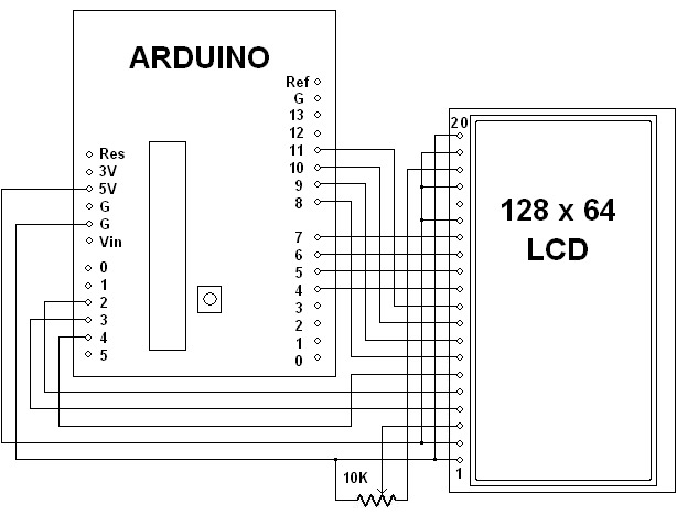
FIGURE 1.
Figure 2 shows what that should look like. Note that I have jumpers over the center barrier of the breadboard. This arrangement makes some more space available for our jumper wires.
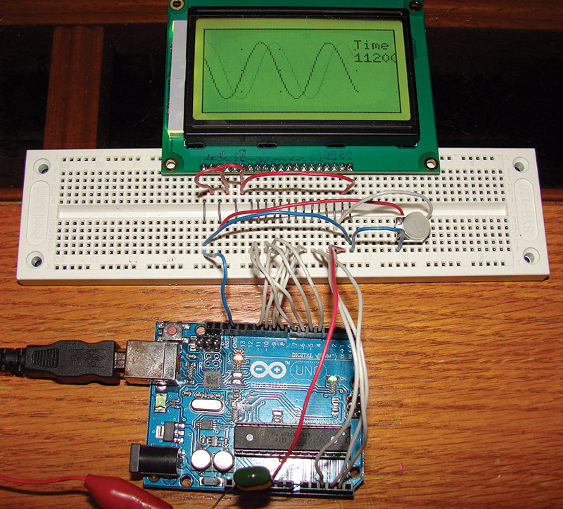
FIGURE 2.
For a sine wave test source, I am using a program called "Audio SweepGen" running on my PC. To connect it to the Arduino analog input A0, there is a little bit of circuitry involved. Figure 3 is the input circuit schematic.
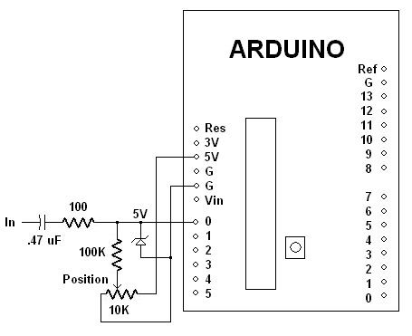
FIGURE 3.
None of the resistor values are critical. You can sometimes get away with just using the .47 µF capacitor, as the Arduino's analog input seems to be naturally self-biasing to around 2.5 volts.
Here is the sketch to determine what the default conversion speed is:
/***********************************
128 by 64 LCD Oscilloscope - Default
By Bob Davis
Uses Universal 8bit Graphics Library, [url=http://code.google.com/p/u8glib/]http://code.google.com/p/u8glib/[/url]
Copyright (c) 2012, [email protected]. All rights reserved.
********************************************/
#include "U8glib.h"
// 8Bit Com: D0..D7: 8,9,10,11,4,5,6,7 en=18,
// di=17,rw=16
U8GLIB_ST7920_128X64_4X u8g(8, 9, 10, 11, 4, 5,
6, 7, 18, 17, 16);
int Sample[128];
int Input=0;
int OldInput=0;
int StartSample=0;
int EndSample=0;
int SampleTime=0;
void u8g_prepare(void) {
u8g.setFont(u8g_font_6x10);
u8g.setFontRefHeightExtendedText();
u8g.setDefaultForegroundColor();
u8g.setFontPosTop();
}
void DrawMarkers(void) {
u8g.drawFrame (0,0,128,64);
u8g.drawPixel (25,16);
u8g.drawPixel (50,16);
u8g.drawPixel (100,16);
u8g.drawPixel (25,32);
u8g.drawPixel (50,32);
u8g.drawPixel (100,32);
u8g.drawPixel (25,48);
u8g.drawPixel (50,48);
u8g.drawPixel (100,48);
}
void sample_data(void){
// wait for a trigger of a positive going input
while (Input < OldInput){
OldInput=analogRead(A0);
Input=analogRead(A0);
}
// collect the analog data into an array
// do not do division by 10.24 here, it makes it
// slower!
StartSample = micros();
for(int xpos=0; xpos<100; xpos++) {
Sample[xpos]=analogRead(A0);
}
EndSample = micros();
}
void draw(void) {
char buf[12];
u8g_prepare();
DrawMarkers();
// display the collected analog data from array
// Sample/10.24 because 1024 becomes 100 = 5 volts
for(int xpos=1; xpos<99; xpos++) {
u8g.drawLine (xpos, Sample[xpos]/10.24, xpos+1,
Sample[xpos+1]/10.24);
}
SampleTime=EndSample-StartSample;
u8g.drawStr(100, 8, "Time");
u8g.drawStr(100, 18, itoa(SampleTime, buf, 10));
}
void setup(void) {
// assign default color value
if ( u8g.getMode() == U8G_MODE_R3G3B2 )
u8g.setColorIndex(255); // RGB=white
else if ( u8g.getMode() == U8G_MODE_GRAY2BIT )
u8g.setColorIndex(3); // max intensity
else if ( u8g.getMode() == U8G_MODE_BW )
u8g.setColorIndex(1); // pixel on, black
}
void loop(void) {
// collect the data
sample_data();
// show collected data
u8g.firstPage();
do { draw(); }
while( u8g.nextPage() );
// rebuild the picture after some delay
delay(100);
}
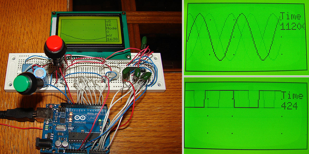
If you run this sketch, you will come up with a number around 11,200 microseconds as seen on the right side of the LCD display. That is a five digit number, so it barely fits on the screen.
We will be looking at two digit numbers before we are done. If you divide one by .0112 and then multiply that by 100 samples, you will get a speed of only around 8.9 thousand samples per second. Figure 4 shows what the default screen looks like.
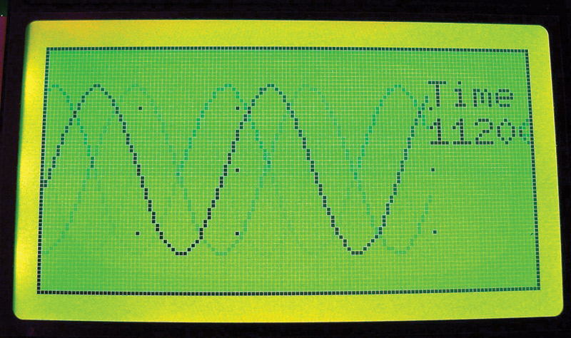
FIGURE 4.
Our next increase in speed will come from sacrificing some accuracy for that extra speed. The ADC is a 10-bit converter. If we don’t need that much accuracy, we can speed up the converter. This can be done by changing the register that scales the clock down to a safe speed for the converter.
This register is called the ADCSRA register and the lowest three bits control the clock scaling. They are normally all set to ones.
We will clear the most significant of those three bits. To do that, right after void loop(void) { add these two lines of code:
// Clear bit 2 of ADC prescalar from 125KHz
// to 2 MHz
ADCSRA &= ~(1 << ADPS2);
Now, upload the newly modified sketch and get ready for a shock. The time should have dropped to around 1,000 microseconds. We have sped up the converter by a factor of 16, but the other instructions kept us from seeing a complete 16 fold increase. If you divide 1 by .001 and multiply that by 100 samples, we are now at around 100 thousand samples per second. Figure 5 shows this screen with that modification.
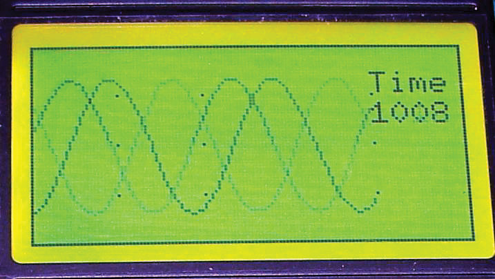
FIGURE 5.
Do you want some more speed? After reading the ADC, the Arduino software shuts it down. We can turn it back on by adding this next code, right after we take the sample with an analogRead (A0):
ADCSRA |= (1 << ADSC); // Restart AtoD Conversion
That should further reduce the time to get 100 samples to 860 microseconds. That is 116,000 samples per second. There are some other tweaks available that might get a little more speed out of the ADC, but these two are the easiest to understand and make the most difference.
Can we keep on speeding it up? Yes, we can! However, we have reached the limits of the internal ADC. So, next we will look at "digital" inputs for a short while before adding an external ADC.
The tricky part will be getting all of the pins of one of the Arduino ports available. To do that, we need to move the three wires on the analog pins A2, A3, and A4 to the digital pins 3, 2, and 1.
Then, we need to change the driver configuration in our code to match. We will replace the line U8GLIB_ST7920_128X64_4X u8g(8, 9, 10, 11, 4, 5, 6, 7, 18, 17, 16); with U8GLIB_ST7920_128X64_4X u8g(8, 9, 10, 11, 4, 5, 6, 7, 1, 2, 3);. Then, upload and run the modified sketch to see if everything still works.
If everything went well, it should still be working. Now, we have all six of the analog pins available. We can use the pins as a logic analyzer with these two changes in our code.
First, the sample collection routine needs to be changed from analog to digital:
void sample_data(void){
// wait for a trigger of a positive going input
while (digitalRead(A0)==0) { }
// collect the analog data into an array
StartSample = micros();
for(int xpos=0; xpos<100; xpos++) {
Sample[xpos]=digitalRead(A0);
}
EndSample = micros();
}
Next, the draw routine needs to be changed to digital, as well:
void draw(void) {
char buf[12];
u8g_prepare();
DrawMarkers();
// display the collected analog data from array
for(int xpos=1; xpos<99; xpos++) {
u8g.drawLine (xpos, Sample[xpos]*16+8, xpos+1,
Sample[xpos+1]*16+8);
}
SampleTime=EndSample-StartSample;
u8g.drawStr(100, 8, "Time");
u8g.drawStr(100, 18, itoa(SampleTime, buf, 10));
}
Using digitalRead instead of analogRead should have reduced your time to 424 microseconds. That is about twice as fast as the fastest analog read was. Using our math formula, the sample rate is now 232,000 samples per second. Figure 6 shows a screenshot.
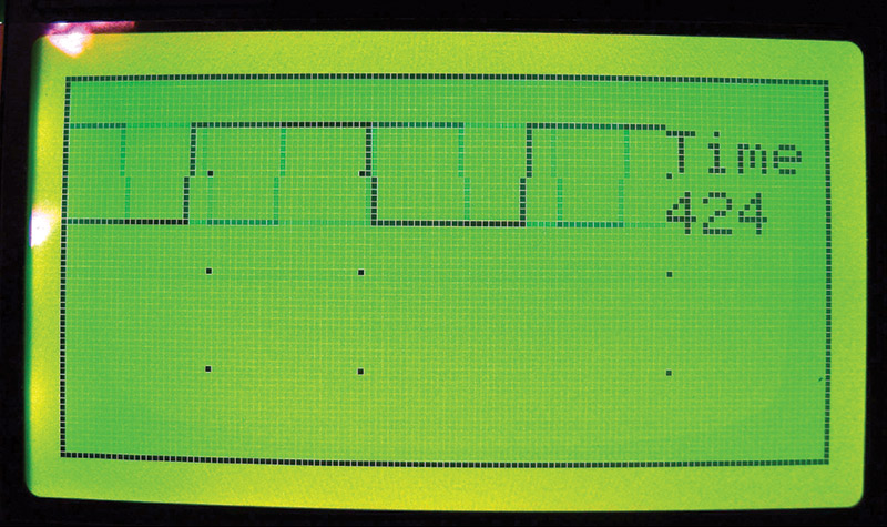
FIGURE 6.
Next, we can replace digitalRead with an even faster way of reading our data. This faster method is to use a parallel input port C or PINC command. That command looks like this: Sample[xpos]=PINC;. Change your code by replacing digitalRead(A0); with PINC; then upload it. You will now get a whopping data collection time of 80 microseconds! Now, we are looking at a two digit number. That is 1.25 million samples per second.
Are we going fast enough yet? Heck no! We can do MUCH better than that! First, do you want to use some of those other analog input pins? Since we are using the parallel input command, we have collected data from all of the analog pins. We just need to display that data.
This gets a little hairy as we have to use Boolean bit masking to pull out the individual bits. To do that, you will need to replace the one line drawLine routine with these six lines of code:
u8g.drawLine (xpos, ((Sample[xpos]&
B00000001)*4)+4, xpos, ((Sample[xpos+1]&B00000001)*4)+4);
u8g.drawLine (xpos, ((Sample[xpos]&B00000010)*2)+14, xpos,
((Sample[xpos+1]&B00000010)*2)+14);
u8g.drawLine (xpos, ((Sample[xpos]&B00000100)*1)+24, xpos,
((Sample[xpos+1]&B00000100)*1)+24);
u8g.drawLine (xpos, ((Sample[xpos]&
B00001000)/2)+34, xpos, ((Sample[xpos+1]&B00001000)/2)+34);
u8g.drawLine (xpos, ((Sample[xpos]&B00010000)/4)+44, xpos,
((Sample[xpos+1]&B00010000)/4)+44);
u8g.drawLine (xpos, ((Sample[xpos]&B00100000)/8)+54, xpos,
((Sample[xpos+1]&B00100000)/8)+54);
Figure 7 shows the LCD screen in logic analyzer mode.
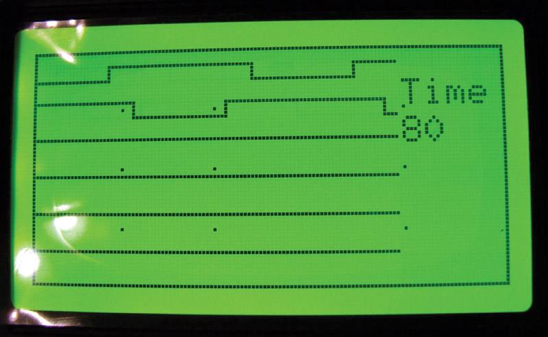
FIGURE 7.
Now, back to speeding things up a bit. Observe that when using integers, we are inputting two bytes of data every time we read the C port. What happens when we replace int Sample[128]; with byte Sample[128];? Try it and take a look.
We are now at 53 microseconds for 100 samples. That is two million samples per second. Can we go faster? Oh ya.
We call the next speed trick the "verbose" method. Using a loop limits our speed because of the time that it takes to loop back. That can be a long time. If we eliminate the "back tracking" and just go forward, we will be much faster.
Use the following code for your sample data collection:
void sample_data(void){
// wait for a trigger of a positive going input
while (digitalRead(A0)==0) { }
// collect the analog data into an array
StartSample = micros();
Sample[1]=PINC; Sample[2]=PINC; Sample[3]=PINC;
Sample[4]=PINC; Sample[5]=PINC; Sample[6]=PINC;
Sample[7]=PINC; Sample[8]=PINC; Sample[9]=PINC;
Sample[10]=PINC; Sample[11]=PINC; Sample[12]=PINC;
Sample[13]=PINC; Sample[14]=PINC; Sample[15]=PINC;
Sample[16]=PINC; Sample[17]=PINC; Sample[18]=PINC;
Sample[19]=PINC; Sample[20]=PINC; Sample[21]=PINC;
Sample[22]=PINC; Sample[23]=PINC; Sample[24]=PINC;
Sample[25]=PINC; Sample[26]=PINC; Sample[27]=PINC;
Sample[28]=PINC; Sample[29]=PINC; Sample[30]=PINC;
Sample[31]=PINC; Sample[32]=PINC; Sample[33]=PINC;
Sample[34]=PINC; Sample[35]=PINC; Sample[36]=PINC;
Sample[37]=PINC; Sample[38]=PINC; Sample[39]=PINC;
Sample[40]=PINC; Sample[41]=PINC; Sample[42]=PINC;
Sample[43]=PINC; Sample[44]=PINC; Sample[45]=PINC;
Sample[46]=PINC; Sample[47]=PINC; Sample[48]=PINC;
Sample[49]=PINC; Sample[50]=PINC; Sample[51]=PINC;
Sample[52]=PINC; Sample[53]=PINC; Sample[54]=PINC;
Sample[55]=PINC; Sample[56]=PINC; Sample[57]=PINC;
Sample[58]=PINC; Sample[59]=PINC; Sample[60]=PINC;
Sample[61]=PINC; Sample[62]=PINC; Sample[63]=PINC;
Sample[64]=PINC; Sample[65]=PINC; Sample[66]=PINC;
Sample[67]=PINC; Sample[68]=PINC; Sample[69]=PINC;
Sample[70]=PINC; Sample[71]=PINC; Sample[72]=PINC;
Sample[73]=PINC; Sample[74]=PINC; Sample[75]=PINC;
Sample[76]=PINC; Sample[77]=PINC; Sample[78]=PINC;
Sample[79]=PINC; Sample[80]=PINC; Sample[81]=PINC;
Sample[82]=PINC; Sample[83]=PINC; Sample[84]=PINC;
Sample[85]=PINC; Sample[86]=PINC; Sample[87]=PINC;
Sample[88]=PINC; Sample[89]=PINC; Sample[90]=PINC;
Sample[91]=PINC; Sample[92]=PINC; Sample[93]=PINC;
Sample[94]=PINC; Sample[95]=PINC; Sample[96]=PINC;
Sample[97]=PINC; Sample[98]=PINC; Sample[99]=PINC;
EndSample = micros();
}
We have now reached a limit that I have not broken yet. Believe me, I’ve been trying. We are now at 20 microseconds to collect 100 samples, or FIVE million samples per second. We have gone from 11,000 to 20 microseconds sample time, which is over 500 times faster. That is about as fast as the Arduino gets.
Figure 8 is the screenshot, with a 20 KC signal being displayed.
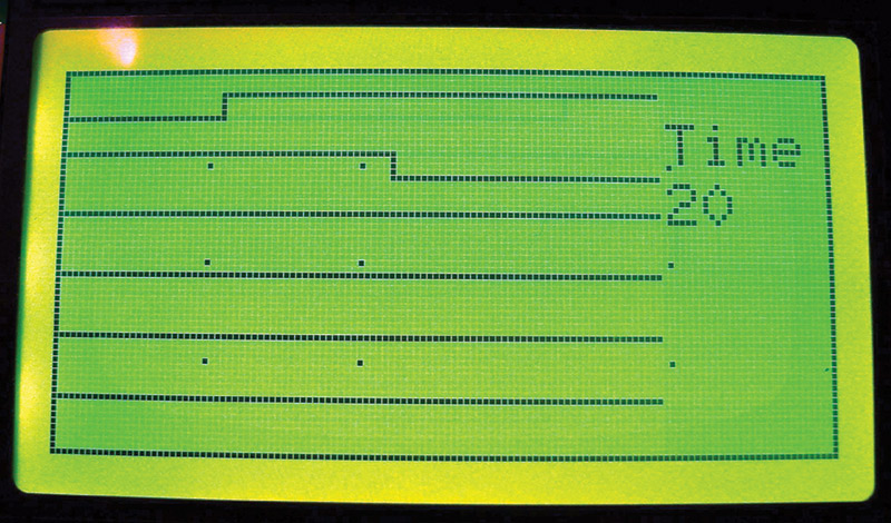
FIGURE 8.
Adding the External ADC
Next, we need to look into adding an external analog-to-digital converter.
There are many things to consider in buying an external ADC. Does it need to fit a breadboard without an adapter? What is the maximum conversion speed that we will need? How many support chips do we want to add? What is the input voltage range we want to monitor?
Many external ADCs are limited to one or two volts peak-to-peak of the analog input signal. Some require that the input be biased at up to four volts. Some converters require a negative power supply. How many bits do we need? Some converters can do six bits, some eight bits, some 10 bits, and some are even 12 bits or more.
I settled on a CA3306 six-bit 15 MC ADC. It is cheap, readily available on eBay, and it has 18 DIP pins that plug easily into a breadboard. For support, the CA3306 only needs three capacitors and a 5-15 MC clock source.
Figure 9 is the CA3306 schematic diagram, modified a little bit from the specifications manual.
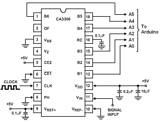
FIGURE 9.
Figure 10 is the clock schematic diagram; you can use any oscillator from 5 MC to 15 MC.
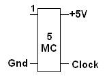
FIGURE 10.
I have even tested it out using up to 25 MC with no problems. However, if you try to connect it to the Arduino clock on pins 9 or 10, the Arduino will slow down or stop.
Once the CA3306 is wired up, you should see a logic analyzer displaying the outputs of it. You need to change the six lines of code for the logic analyzer back to an oscilloscope type display like this:
u8g.drawLine (xpos, Sample[xpos], xpos+1,
Sample[xpos+1]);
If you are using a 20 KC sine wave, you will only be seeing 1/4 of the waveform. You can slow it down by replacing the 100 PINCs with the older data sampling version that used a loop and PINC.
Figure 11 shows the CA3306 ADC. The clock oscillator was located at the other end of the breadboard. Figure 12 is the LCD with the external ADC.
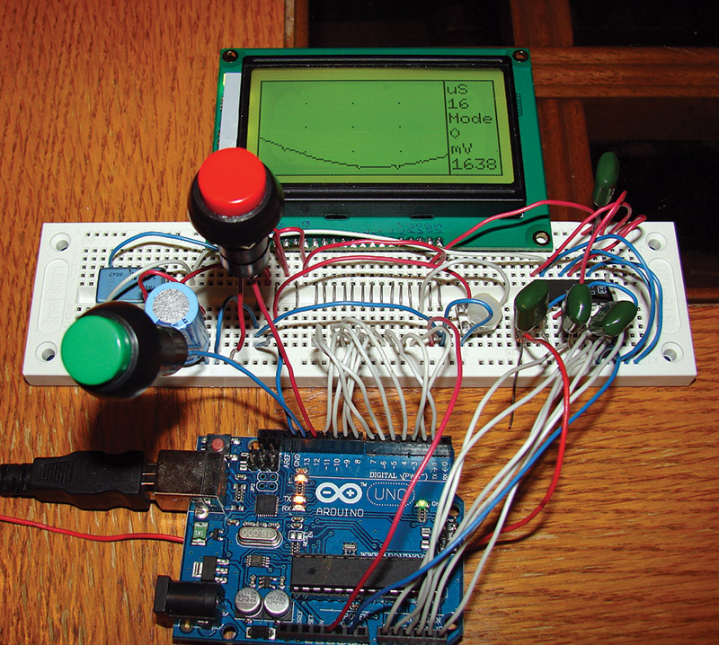
FIGURE 11.
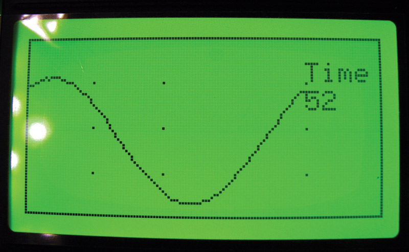
FIGURE 12.
If you connect the analog input circuit that was shown earlier to the CA3306, the position control will not work very well. The reason is that the CA3306 has low input impedance. To compensate for that, we could add a better analog input section. An LF353 or TL082 dual op-amp can provide gain up to about 4 MC and over one million ohms of input impedance, as well as fixing the position control issue. The drawback is that it requires a positive and negative nine to 12 volt power supply. Two nine volt batteries will work. If you are building a portable wave form viewer, you may already have the Arduino running on a nine volt battery, so adding a second one might not be as big of a problem. Figure 13 is a simple analog input schematic diagram.
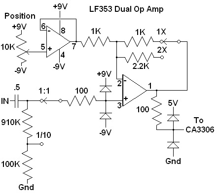
FIGURE 13.
Next, the switches are connected from D12 and D13 to ground. They are scan frequency "up" and "down" buttons. Then, the software can select between the verbose method and the loop method for collecting the data. Once using the loop method, a delayMicroseconds (dtime); command can be added. The delay value can then rotate between 1, 5, 10, 50, 100, 500, 1,000, and 5,000 at the push of a button. The complete code for the final version is available at the article link.
Figure 14 is a screenshot of the completed oscilloscope.
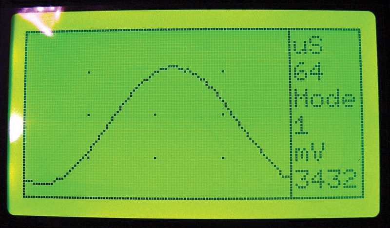
FIGURE 14.
The top right shows the time it took to collect 100 samples; below that is the sample mode selection, and at the bottom is the millivolt reading based on an ADC that takes a five volt input for a full scale reading.
That’s a Wrap
Are faster speeds possible? Yes! With an AD775 25 MC ADC and a DS2010 FIFO, I have reached speeds of 25 million samples per second. A FIFO is a memory device that features a memory organization that results in "First In First Out." You can record data to a FIFO at its maximum clock speed, then play it back at much slower speeds. I suspect that with the right ADC and FIFO you could reach 100 million samples per second. Is that practical? No. If you add a FIFO, it then controls the sampling speed. So, you would also need to add two or three 74LS390s and a switch to select the sampling speed. At this point, the Arduino is controlling almost nothing other than the LCD.
If you were using an Arduino Mega, you would have enough pins to add a 74LS138 or two as frequency selectors, and to control relays for the input attenuation and gain switches. In fact, you would have enough pins to add a second ADC and FIFO to make a dual-channel 100 million samples per second oscilloscope. The Arduino Uno lacks the data pins that are needed to make a really good oscilloscope. NV