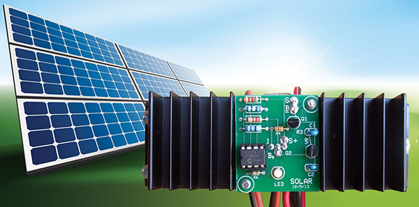
Several readers have asked for an inexpensive solar controller kit for charging 12 volt lead-acid batteries. The specifications for this project (given by one of the readers) were to control the charging of lead-acid batteries up to 12 amps using solar cells. He wanted the unit to start charging if the battery voltage went below 13.5 volts, and then turn the charging off when it reached 14.25 volts.
This project is very inexpensive and fits onto a heatsink that is mountable. Since the voltage is low, there is no danger of shock. It is simple to build, ideal for the novice, and no special tools are needed other than a soldering iron and a 9/64" drill.
Battery Functions
To charge a battery, the charging voltage of the charging device — whether solar or a regular battery charger — has to produce a voltage above the battery voltage itself. If you think of a battery as a big resistor, the picture becomes clearer. Lead-acid batteries have a resistance of approximately 20 milliohms. However, the charging resistance of a battery appears to be considerably higher. The amperage will also be limited by the output of the charging device and its resistance. It will merrily drop its charging voltage which will limit its charging amperes.
If the resistance of the charger is one ohm, it produces 14.5 volts; the battery is at 13.5 volts, so its output is limited to:
1 volt / 1 ohm = 1 amp
If one connects a bank of solar cells to produce voltages over 14.5 volts, the solar panel will continue to overcharge the battery which will cause the battery acid to disassociate its water into oxygen and hydrogen, and the battery will get hot and boil:
2 H2O = 2H2↑ + O2↑
Therefore, the charging voltage should be limited to 14.25 volts. I was concerned this might be too high, so I lowered it on this project to 14.00 volts. Gassing will take place at 14.25 volts if the temperature exceeds 30°C. On the other hand, if the battery is allowed to discharge completely, it will form lead sulfate crystals. These are hard to get back into a solution. This is called sulfation:
Pb(solid) + PbO2(solid) + 2H2SO4(aqueous) ® 2PbSO4(solid) + 2H2O(liquid)
Lead-acid batteries are constantly discharging due to their nature. They will lose approximately 1% of their charge per day. This is why you should never store lead-acid batteries for long periods of time. In the good old days, the rule of thumb was to use a trickle charger, and it is still a good idea. It was often a small transformer with a diode that provided one half wave rectification that produced 13.5 volts at .25 amps.
Older voltage regulators in cars use a simple regulator with a heavy relay. The coil of the relay was connected across the generator, and its points connected the generator to the battery. When the generator is producing voltage, it induces a magnetic field into the coil and closes the contacts. The contacts allow the battery to charge.
When the generator slows down, there is not enough current to hold the contacts closed, so it disconnects the generator from the battery. As you can see, this system does have the potential to overcharge a battery since nothing is measuring the voltage of the battery to see if it exceeds 14.25 volts.
Some of you are probably asking why we need to disconnect the battery from the generator. When the generator is not generating, it becomes a motor.
Wow! I think I just discovered a potential perpetual motion machine! Why not take a circular raceway (or better yet, an oval raceway) and raise one end. Take a generator and battery, connect them together, and put them on a cart. When the cart goes downhill, it will charge the battery; when the cart starts uphill, the generator will become a motor and drive the cart uphill.
But I digress ... back to the use of relays. Relays are good as they have very low contact resistance. However, the contacts do arc and the setup is mechanical. (Not good for speed nor endurance.)
Silicon devices such as triacs, SCRs, transistors, FETS, etc., have the advantage there is not much to wear out and they can work at high speeds. They will burn out, however, if not properly heatsunk. Where does this heat come from? Silicon devices like diodes and transistors often have a voltage drop of something equal to .8 volts. The FET I’m using is a P-MOS IRF5305PBF which has a resistance of .06 ohms from source to drain when running in the saturated mode. One watt will produce 14.3 calories per minute since a calorie is equal to raising 1 gm (or at 1 ml) of water 1°C in one minute. So, 14.3 calories would raise 14.3 gms of water one degree. A tablespoon of water is about 15 gms.
When 12 amps are drawn with a resistance of .06 ohms, the voltage drop across the FET is .72 volts:
.72 volts * 12 amps = 8.7 watts or @ 120 calories
If we take a tablespoon of water at 25°C (room temperature) and place it on the transistor, in one minute it will raise the tablespoon of water to 34°C (93°F). In seven minutes, the water would boil. Now, you should understand why we need to heatsink silicon devices. A great website for the calculation of heat transfer to a heatsink is at www.mustcalculate.com.
The Circuit
To measure the voltage of the battery, I used a PIC16F675 which has a 10-bit A/D (analog-to-digital) converter. This allows you to get down to /.0049 volts per bit (five volts/1,024 bits). A voltage divider using 1% resistors reduces the voltage down 1:10, so 14.00 volts cut-off voltage will be 1.400 volts, or 286 bits. The turn-on voltage is set to 13.5 volts which equates to 1.35 volts or 275 bits. The PIC is powered at five volts with a 7805L using the battery voltage; see the schematic.
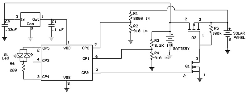
Solar controller schematic.
A P-MOSFET is used to turn the solar panel on and off. The one used here is capable of sinking 31 amps. Keep in mind, though, the heatsink is the key. MOSFETs have the advantage of a low resistance when they are run in the saturated mode. A second N-MOSFET is used as a voltage translator as the five volts from the PIC will not totally turn off the P-MOSFET.
The P-MOSFET is run either fully on or off. It is connected to the positive lead of the battery from the positive lead of the solar panel. The PIC measures the voltage on the battery by bringing the FET high, thus disconnecting the solar panel from the battery. It then determines if the battery needs to be charged by measuring its voltage.
If it does need charging, it connects the positive line of the solar panel to the positive terminal of the battery. If not, it continues to monitor the voltage until the battery voltage goes below 13.5 volts. It then connects the positive side of the solar panel to the positive terminal of the battery and allows its voltage to charge the battery.
To prevent the unit from drawing excessive power, I measure the voltage across Q2 that controls the charging. The PIC measures the battery voltage and the solar panel voltage, and takes the difference. If the voltage is over 1.25 volts (about 20 amps), it goes into the alarm mode and turns the FET off. The LED will blink off and on red. It will automatically reset.
FETs will also conduct both ways, thus creating a potential that the batteries could discharge through the solar panel. To prevent this, an algorithm is used, and when the solar voltage drops below the battery voltage the unit disconnects from the solar panel. This prevents discharge when the sun goes behind a cloud or the sun goes down. Once every 10 minutes, the battery is disconnected from the solar cell and its voltage is checked. When the battery reaches 14.00 volts, the solar panel disconnects and the micro continues to monitor until the battery’s voltage reaches 13.5 volts. It then re-connects to the solar panel.
Building the Circuit
A kit is available from the Nuts & Volts Webstore. It comes with a preprogrammed chip and board. If you want to program your own chips, you will need a programmer. The printed circuit board (PCB) files are available at the article link, along with the assembly and hex files for the PIC, plus some usage hints and tips, and a copy of the Parts List. The board files are from ExpressPCB and can be downloaded with their free software. If you are a programmer, you can change the tripping voltages if you feel so inclined. (Refer to the Hints and Tips file at the article link.)
Place the heatsink with its mounting holes facing down; rotate it so that its single mounting hole is to the right. Using the template available with the downloads, cut the template out and glue it on the top of the heatsink. Drill three holes using a 9/64”drill and deburr. Make sure the heatsink is flat with no burrs. Remove the template with hot water. Take a look at Figure 1.
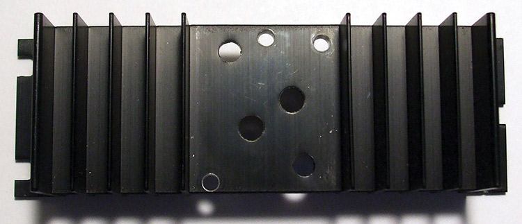
FIGURE 1.
With Q2 facing you, bend its leads toward you 90 degrees so they are facing up. To prevent the heatsink from becoming a conductor, locate the insulating pad and place it on the heatsink. Mount the FET using the 6-32 nylon screw and nut. The screw should be on the back of the heatsink; the nut should be on top of the FET. The purpose of this is to allow the removal of the transistor and board without having to de-solder. Refer to Figure 2.
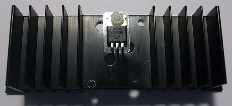
FIGURE 2.
Solder the six resistors and two capacitors to the board. If you have trouble reading color codes, use an ohmmeter. The board is marked. Solder the voltage regulator to the board with its flat pointing to the center of the board and Q1 to its pads noting its markings. Solder the socket for IC1 with lead 1 going to the square pad. Solder the LED with its long lead to the square pad. Check out Figure 3.
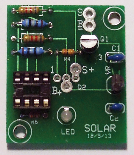
FIGURE 3.
Solder two #18 black wires to the negative pads and two #18 red wire to the positive pads as in Figure 4.
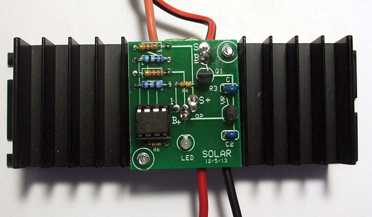
FIGURE 4.
Some of you will be asking, “Wouldn’t it be better to move the pads for the wires closer to the edge?” It would be more convenient. However, PCB traces don’t fare well with high amperage. If you calculate out the width of the trace needed to transfer 12 amps with 1 oz of copper trace, it would have to be .5” wide — one-third of the board width.
Thread Q2’s leads through the board transistor pads. Speaking from experience, make sure the resistors are next to the body of Q2 (Figure 5). Mounting the board in backwards will reverse the leads of Q2 and will cause failure. Use the two 1/4” nylon spacers and two 5/8” 6-32 screws. Put the screws through the back of the heatsink and screw them into the board. The board will self-tap. Solder Q2’s leads.
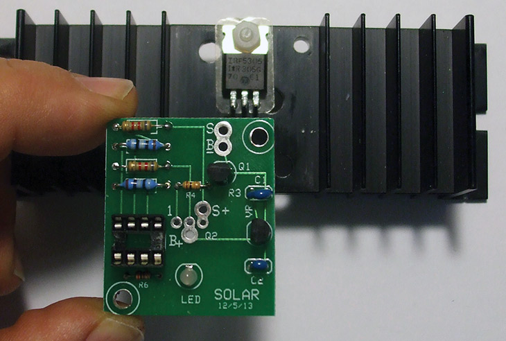
FIGURE 5.
There are mounting slots on the heatsink for mounting the unit.
Using the Unit
Using wire nuts, connect the unit to the batteries first. The LED should turn on. Green shows the batteries are charged (or the solar panel voltage is below the battery voltage); red indicates the batteries are charging. Now, connect to the solar panel.
You might want to consider adding an amp meter and an inline fuse. The LEDs only show what the battery is calling for and does not indicate that the solar panel is charging.
Happy are those who keep themselves (and their batteries) charged up! NV
PARTS LIST
| ITEM |
DESCRIPTION |
PART # |
QTY |
SOURCE |
| C1 |
0.33 µF |
810-FK28X5R1E334K |
1 |
Mouser |
| C2 |
0.1 µF |
81-RDEF51H104Z0K103B |
1 |
Mouser |
| IC1 |
PIC12F675-I/P |
579-PIC12F675-I/P |
1 |
Mouser |
| LED1 |
Bi-colored LED |
160-1058-ND |
1 |
Digi-Key |
| Q1 |
N-MOSFET - 2N7000 |
119423 |
1 |
Jameco |
| Q2 |
P Power MOSFET - IRF5305 |
IRF5305PBF |
1 |
Jameco |
| R1, R3 |
8.2K ohm 1/4W 1% |
18.2KXBK-ND |
2 |
Digi-Key |
| R2, R4 |
910 ohm 1/4W 1% |
909XBK-ND |
2 |
Digi-Key |
| R5 |
100K ohm 1/6W 5% |
100KEBK-ND |
1 |
Digi-Key |
| R6 |
220 ohm 1/6W 5% |
220EBK-ND |
1 |
Digi-Key |
| VR |
IC Reg LDO 5V 0.1A |
497-2952-5-ND |
1 |
Digi-Key |
| In-line |
Diode Schottky 45V 12A |
|
1 |
|
| PCB |
Printed Circuit Board |
|
1 |
Express PCB |
| HS |
Heatsink |
GHT144-R |
1 |
Jameco |
| Socket |
8-pin IC socket |
AE9986-ND |
1 |
Digi-Key |
| Ther. P |
Thermal Pad |
926-1483-ND |
1 |
Digi-Key |
| Screw |
6-32 3/4" |
H164-ND |
2 |
Digi-Key |
| Screw |
6-32 3/8" Nylon |
H556-ND |
1 |
Digi-Key |
| Spacer |
1/4” Nylon |
492-1104-ND |
2 |
Digi-Key |
| Nut |
6-32 Nylon |
H620-ND |
1 |
Digi-Key |
| Wire |
Black Stranded wire (1 ft) |
125787 |
1 |
Jameco |
| Wire |
Red Stranded wire (1 ft) |
125736 |
1 |
Jameco |
Downloads
Template, Tips, PCB, schematic and Code files. (Files Updated: 3/25/14*)