I love restoring old electronic equipment, bringing things back to life. A while ago, I was excited to find a vintage Heathkit EC-1 analog computer for a reasonable price on eBay. It definitely needed a little TLC.
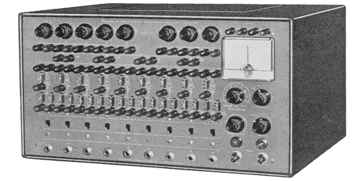
The Heath Company originally sold the EC-1 from 1959 to 1971 for $199.95. It had 17 vacuum tubes and lots of knobs and banana jacks in an awesome front panel. Figure 1 (above) is a picture from the Heathkit catalog. Nowadays, they show up on eBay on a fairly regular basis, but some of them can be quite expensive at well over $1,000.
Nothing is Ever Simple
When I bought the computer, I knew I was in for a major cleanup after seeing the photos on eBay. Figure 2 shows the unit just after I unpacked it. At first, I thought that a little 409 cleaner would do the job, but I soon realized that I would have to completely disassemble it and unsolder every component in order to bring it up to my standards.
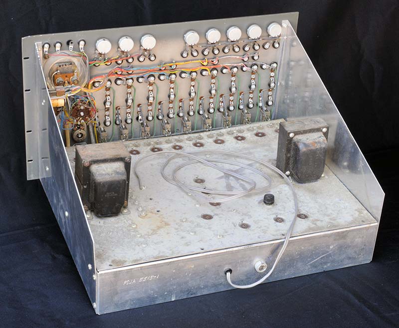
FIGURE 2. This EC-1 was purchased on eBay for $420. It obviously needed a major restoration.
I wasn’t planning on restoring it to an all-original museum piece, but I did want it to look nice and work. The finished restoration is shown in Figure 3.
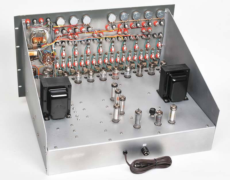
FIGURE 3. The finished restoration included new vacuum tubes, tube sockets, binding posts, potentiometers, and a line cord.
I was pleased with the result. The old metal cabinet had some light rust on it and I had planned on trying to match the original Heathkit gray wrinkle paint. After unsuccessfully trying a few automotive sprays, I went for the ultimate: a gray hammertone powder coat. The finish looks great (as you can see in Figure 4) and it’s tough as nails.
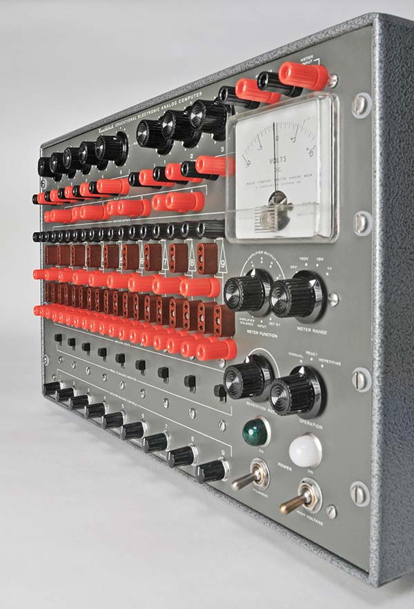
FIGURE 4. The new binding posts enhanced the look of the front panel. The nine “amplifier balance” pots along the bottom had degraded during the past 50 years and were replaced.
The front panel was missing a red binding post, and the rest of the posts were dirty and tarnished inside. I tried finding a matching post, but in the end I bought six dozen brand new ones. Their bright color gives the front panel a real pop.
Taking the unit apart was easy. It was putting it back together and pre-testing each circuit that took the time. I took lots of “before” digital pictures and made sketches of the critical wiring so I wouldn’t lose track of things. A few days later when I was surfing the Internet, I was amazed to come across scans of both the original Heathkit EC-1 assembly and operational manuals. They were available as two 40+ page pdf files and contained complete schematics for the amplifiers, power supplies, and front panel controls. To download the manuals, please see the web address in the Resources Section.
Some Advice
If you are ever thinking about buying and restoring a piece of electronic equipment, I have several bits of advice for you to consider:
- Be sure the front panel and its silk screening are as clean as possible. It can be difficult to restore the delicate silk screening or big scratches. Plus, any calibration or inventory stickers can leave discolored areas.
- If you are buying a unit on eBay, be sure you see at least one photo of the interior. Sometimes bad things can be found within, like overheated transformers, water damage, missing parts, etc.
- A little grime is okay, but extensive corrosion or a broken one-of-a-kind component can be hard to replace or restore.
Getting to Work
One of the big no-no’s with vintage equipment is to plug it in the wall to “see if it works.” Even using a variac is not the best way. Some components — like electrolytics — tend to degrade with time, and if you apply full voltage they can actually explode. So, the trick is to either “re-form,” rebuild, or replace them. The Internet contains a plethora of excellent advice on how to re-form electrolytics. Sometimes it’s successful, sometimes not. For this restoration, I chose to rebuild the electrolytics and replace the smaller caps with modern ones. Figure 5 illustrates the four steps I took to dissect the old electrolytics and slide the new ones inside the paper sleeves. I thought that using the original sleeves would give the restoration a more vintage look.
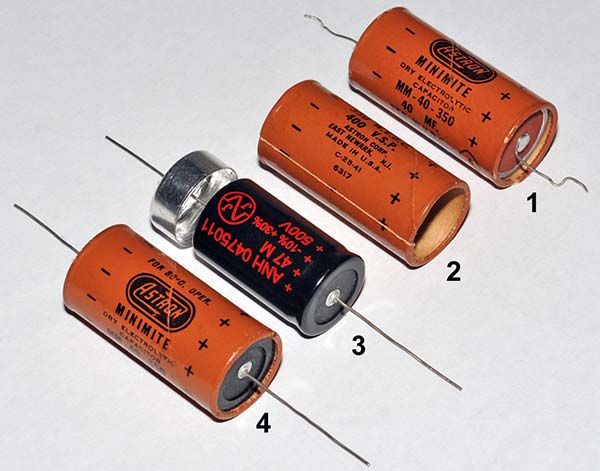
FIGURE 5. Rebuilding the large electrolytic capacitors involved slipping new capacitors into the old paper sleeves to retain the vintage look.
After all the other components had been unsoldered, I measured a number of the carbon resistors and potentiometers (pots), and was surprised to find that many were out of spec. So, I decided to replace them all. The wire-wound power resistors were fine.
The only major deviation from using all original parts was the replacement of the nine “amplifier balance” pots located along the very bottom of the front panel, as seen in Figure 4. During the past 50+ years, the original pots had degraded in value, from 3,000 ohms to as low as 2,150 ohms, and several of them didn’t even have enough range to balance the amplifiers. The original pots had screwdriver adjustment slots, but I chose to buy pots with shafts and add a small knob because this way, they were much easier to adjust. They made the front panel look different from the original, but what the heck.
The rectifiers were a strange mix of silicon and series-wired selenium diodes. I had never seen a potted selenium rectifier, so I cracked one open and found the usual stack of plates; they were small, rated at 50 ma. A photo of them can be seen in Figure A below.
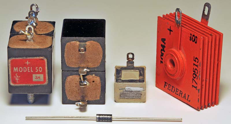
FIGURE A. The dissected selenium rectifier is on the left of the more typical orange selenium rectifier made by Federal. A modern diode is in the foreground.
In days past, if you’ve ever experienced an overheated selenium rectifier, you will never forget the unique smell. In this restoration, they all were okay, so I remounted them in the chassis. I replaced the dissected unit with a modern silicon diode.
Buying New Parts is Fun
On the upside, the most enjoyable thing for me was ordering new parts from places such as Antique Electronic Supply (www.tubesandmore.com) in Tempe, AZ. They have hard-to-find things like high voltage capacitors, wafer-type tube sockets, square bus bars, and terminal lug strips.
The computer arrived at my door with only half its vacuum tubes, but that was a trivial problem because many types of tubes are still available and not too expensive. Fortunately, the EC-1 didn’t use any of the outrageously expensive power tubes used in vintage guitar amplifiers.
My biggest worry was breaking one of the delicate contacts on the wafer switches. The switches would be almost impossible to replace because of their custom wipers. So, I wicked the solder off the lugs, carefully removed the wires, and luckily nothing broke. The wiping contacts were tarnished a bit but a little silver cleaner worked wonders.
The aluminum chassis had some minor corrosion, so I used a small handheld orbital sander to moderate the spots and to impart a more brushed look to all the chassis panels. It helped to hide the minor scratches and abrasion marks. The final prep was a scrubbing with the type of green abrasive pad typically found in kitchens, which gave the panels a nice luster.
Final Assembly and Test
My approach to the final assembly involved wiring up and testing the power supplies first. I love OA2 and OB2 regulator tubes with their warm glow discharges. Once the +300V, -150V, and three 100V power supplies were checked out, the rest of the components easily fell into place using the assembly manual, digital photos, and notes taken during disassembly. It’s always sweet to replace old brittle rubber grommets with new pliable ones. Figure 6 shows the new and rebuilt parts mounted in the chassis. Notice the five parallel bus bars which distribute the AC and DC voltages to the operational amplifiers (op-amps).
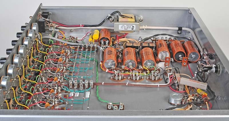
FIGURE 6. The chassis was completely rewired using a mix of original and new parts. The five parallel bus bars distribute the +300 VDC, -150 VDC, and 6.3 VAC.
Actually, firing up the reborn Heathkit was a non-event since I had thoroughly tested or replaced almost every component. The nine op-amps balanced fine using the new pots, and adjusting them with their new knobs was much easier than messing around with a screwdriver.
It was then that I hit the proverbial wall. Now that everything’s working, what’s next? My friends thought it looked nice but they wondered what it was good for. Then, I remembered a diagram in the back of the EC-1 operational manual that described an interesting application: the simulation of a bouncing ball. The potentiometers on the front panel could be set up to vary the effects of gravity, mass, damping, and spring rate on the ball. The output signals would go to an X-Y oscilloscope so you could graphically see the motion of the ball.
Bouncing Ball Simulation
Figure 7 is the schematic of the simulation, which used all nine op-amps, dozens of resistors, a few capacitors, and a couple of diodes.
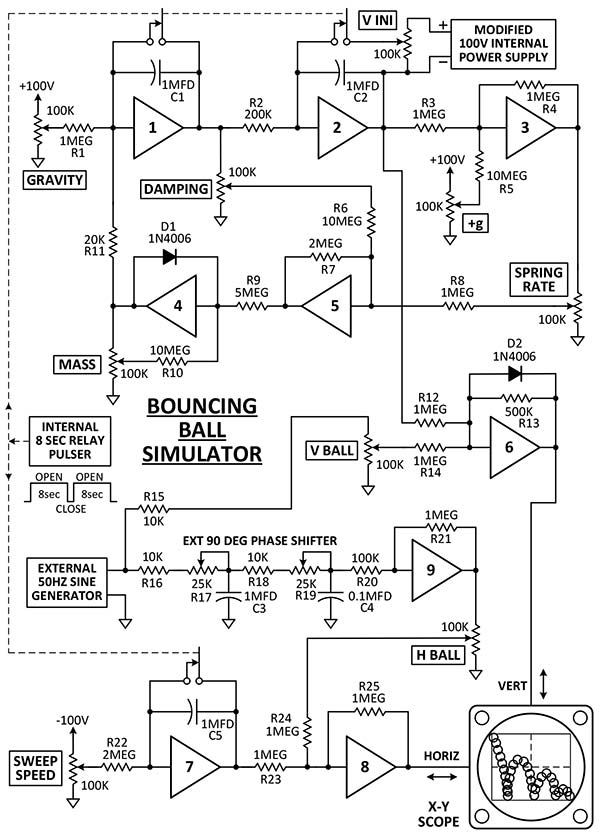
FIGURE 7. One of the classic demos for an analog computer was to simulate a bouncing ball. The op-amps were configured as summers, multipliers, dividers, integrators, and inverters.
Each op-amp was basically an inverting amplifier with an open loop gain of approx. 1,000 and an output range of +60V. FYI, a schematic of the nine identical op-amps is shown in Figure B. A listing of the components used for the simulation can be found in the Parts List.
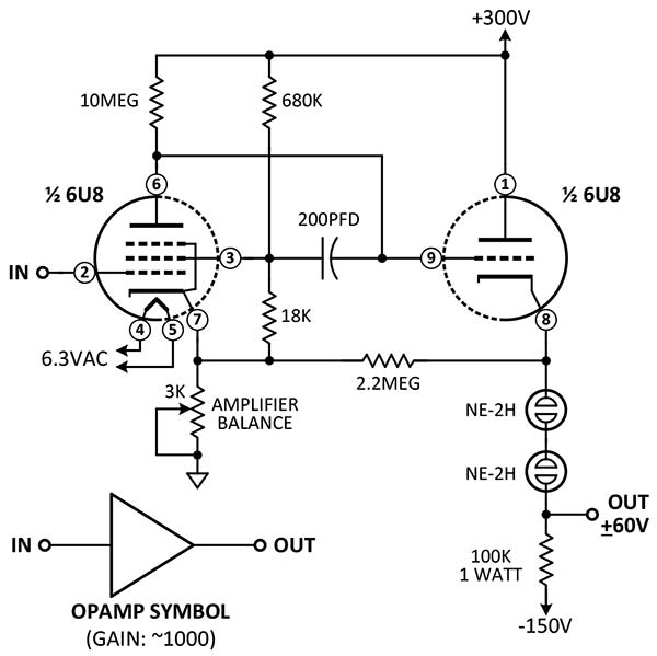
FIGURE B. The nine 6U8 operational amplifiers have an open loop gain of ~1,000 with an output of +60 volts. The frequency response is -1 dB at 600 Hz.
The operational manual that I downloaded had a large section devoted to explaining the basics of using op-amps to do addition, subtraction, inversion, multiplication, integration, and differentiation. Plus, it thoroughly explained how the op-amps were used to implement the differential equations used by the bouncing ball simulation.
However, I realized there was something missing. The original kit of parts had included 27 two-pin clear plastic plugs to hold the simulation resistors and capacitors. In turn, the plugs would have been plugged into the 27 two-pin brown sockets on the front panel, as seen back in Figure 4. The unit I purchased had no plastic plugs! I checked eBay ... no joy. Of course, I could have simply slipped the resistor and capacitor leads into the holes in the red and black binding posts and then tightened down the knurls, but that would have been much too easy. I wanted the original plugs or something like them.
The answer was to use my Grizzly benchtop milling machine to make them. I changed the design a bit and potted the resistors in hollowed out blocks of delrin plastic. The pins I needed just happened to be the same size as the pins in old octal vacuum tubes, so I yanked a bunch of them out of 6SN7s and 6J6s. Then, I crimped them onto the component leads and potted the assemblies into the plastic blocks as seen in Figure C. Done.
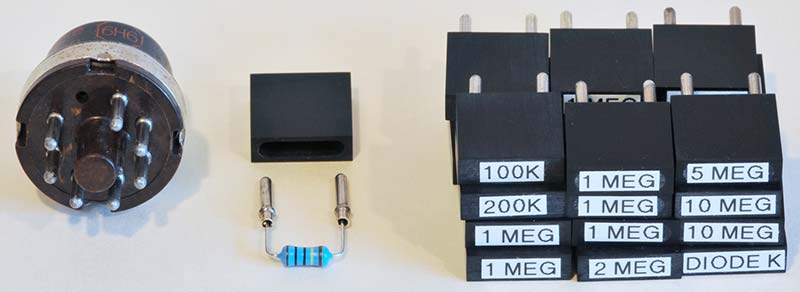
FIGURE C. The resistors and diodes used in the bouncing ball simulation were crimped to old octal tube pins and potted in plastic housings.
A Rat’s Nest Did the Job
Using the simulation schematic, I crisscrossed the front panel with 35 red and black Pomona patch cords, from 4” to 24” long; refer to Figure 8. It was a real rat’s nest. I couldn’t stop myself from displaying the output on a vintage Heathkit IO-10 3” scope that I had recently restored. I had other scopes, but I thought the little IO-10 was a fitting match. I’ve always liked the IO-10 because it had knobs that were somewhat similar to the ones found on Tektronix scopes.
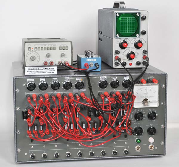
FIGURE 8. The simulation required 35 patch cords, 25 resistors, 11 pots, five capacitors, two diodes, and all nine op-amps.
Figure 9 was the grand finale. The simulation cycle relay was set at an eight second period, and when the relay contacts opened, the ball dropped and bounced for eight secs, then returned to the initial starting position and repeated. It was mesmerizing. The various effects on the motion of the ball were adjustable by the pots on the front panel over a wide range.
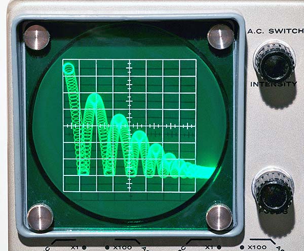
FIGURE 9. An X-Y oscilloscope was used to display a bouncing ball. The repeating horizontal sweep was approx. eight seconds. Notice that the ball flattens out on the first several bounces.
You could simulate the gravity on the moon or the earth, and the simulated ball could be made of steel or even a super ball that never stopped bouncing. There were plenty of variations to explore.
Although looking back, all was not well when I first turned on the simulation. The ball on the scope was a mess of zig-zag lines — not round at all. A 60 Hz hum was somehow getting into the op-amps. After much hair pulling, I traced the problem to the Vertical Initialization (V INI) power supply. It wasn’t isolated enough, so I added a small 120 VAC transformer under the chassis and the ball cleaned right up.
In closing, the EC-1 was a fun and challenging project, and I learned a great many new things. However, I think I’ve taken the bouncing ball as far as it can go, so now I’m casting around for other interesting simulations to try.
What’s Next?
In the meantime, I have a new quest: to search eBay each and every day until I find the quintessential Heathkit analog computer — the ES-400. It has even more op-amps and vacuum tubes than the EC-1, plus a sloped panel packed with enough components to take your breath away. Just Google the Heathkit ES-400 and you’ll see what I mean. NV
Parts List
| Designator |
Component |
Digi-Key, unless noted |
| R1, R3, R4, R8, R12, R14, R21, R23-R25 |
Resistor, 1 meg, 1/2W |
1.0MH-ND |
| R2 |
Resistor, 200K, 1/2W |
200KH-ND |
| R5, R6, R10 |
Resistor, 10 megs, 1/2W |
10MH-ND |
| R7, R22 |
Resistor, 2 megs, 1/2W |
2.0MH-ND |
| R9 |
Resistor, 5 megs, 1/2W |
5.0MH-ND |
| R11 |
Resistor, 20K, 1/2W |
20KH-ND |
| R13 |
Resistor, 500K, 1/2W |
510KH-ND |
| R15, R16, R18 |
Resistor, 10K, 1/2W |
10KH-ND |
| R20 |
Resistor, 100K, 1/2W |
100KH-ND |
| R17, R19 |
Potentiometer, 25K |
*R-V38-25KL |
| C1, C2, C3, C5 |
Capacitor, 1 mfd, 630V |
*C-FS-630-1MFD |
| C4 |
Capacitor, 0.1 mfd, 50V |
399-4151-ND |
| D1, D2 |
Diode, 1N4006 |
1N4006FSCT-ND |
| * Antique Electronic Supply |
The Rise and Fall of Electronic Analog Computers
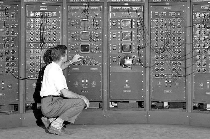
In 1949, the large electronic analog computing machine shown here was located at the Lewis Flight Propulsion Laboratory in Ohio. It contained thousands of vacuum tubes and was capable of modeling fluid flow, pressure, temperature, and other parameters required by the early space program. The advantage of this type of computer was that it could electrically model and simulate many fluidic and mechanical systems without having to actually build and test expensive hardware. They were used to run varying simulations of a system and when the results had converged on an optimal solution, the actual hardware could be designed and constructed with a greater confidence that it would meet the required performance.
Several of the larger analog machines included Enrico Fermi’s FERMIAC, Reeves’ REAC, Beckman’s EASE, and Project Typhoon developed by RCA in 1952. The RCA machine contained over 4,000 vacuum tubes, 100 dials, and 6,000 plug-in connectors. The simulations were set up by plugging numerous patch cords into large patch panels.
However, as digital computers became more capable, the hybrid digital/analog computer was born and stand-alone analog computers began to fade. Eventually, digital computers had advanced enough in speed, memory, and software to handle models and simulations that exceeded even the capabilities of hybrid computers, so they became obsolete. Fortunately, some of the original analog machines can still be found in museums around the world for visitors to enjoy.
Resources
Vintage electronic parts
www.tubesandmore.com
EC-1 manuals
www.computerhistory.org/collections/catalog/102649920
Catalog of Heathkits
Heathkit Test Equipment Products
by Chuck Penson