Rarely on the schematic, but crucial to good performance!
For low frequency control, switching, and DC power, it is possible to get the job done without worrying too much about wiring and cabling practices. If Point A is supposed to be connected to Point B and the ohmmeter says it is — that’s generally sufficient. The “fun” usually begins when the operation of Circuit A starts disrupting the operation of Circuit B, or if the project involves low-level audio such as from a microphone or pickup coil. If there is a nearby transmitter of any sort or perhaps a sensitive receiver, RF gremlins might begin to appear. Suddenly, a whole new set of cautions and constraints gets piled on to your “simple” project. In this column, I’m going to provide an overview of shielding, including some practices you should know as a defense against these gremlins.
Shielded Cables
Most readers will have some sort of shielded cable in their parts inventory. Maybe it is a shielded audio cable with one or two conductors inside an outer shield of thin foil or fine wires wrapped around them. Maybe it’s a multi-conductor control cable with a braided shield. Either way, the goal of using these cables is twofold: to prevent (or at least reduce) signals inside the cable from coupling to other circuits or cables; and to prevent stray electromagnetic fields from creating voltages and currents in the conductors inside the shield. So far, so good.
In most of these cables — particularly those intended for use with audio or RF below 1 MHz — if you strip back the shield, you’ll see that the conductors are twisted together. (The number of times per inch or cm that the wires are twisted together is called the pitch.) This is done for a couple of reasons. First, twisting the conductors keeps them pressed together so there is a minimum of area between them. This helps reduce the voltage induced in the conductors by an external field (see the sidebar).
Loops: Keep Them Small
Back in the early 19th century, Faraday discovered that a changing magnetic field enclosed by a wire would induce a voltage in that wire. This relationship became known as Faraday’s Law. Any loop formed by conductors — whether they are wires in a piece of equipment, conductors in a cable, or traces on a printed circuit board (PCB) — will pick up a signal from a stray magnetic or electromagnetic field. Similarly, varying current flowing in a loop will create and radiate a signal that can be a source of interference.
An easy and inexpensive way to keep a circuit from becoming a source or victim of interference is to simply twist the wires together so that the area of the loop they form is small. Or, lay out PCB traces for a signal and its return path next to each other. The higher the current carried by the loop or nearby conductors (such as for motors or appliances), the more important this becomes.
Second, it maintains electrical balance of the conductors so they all look about the same to an external field. This keeps signals that may be coupled to the cable on all conductors (common mode signals) from being converted to signals that are not the same on different conductors (differential mode signals), and so interfere with the desired signals. Figure 1 shows examples of common and differential mode signals on different types of cables.
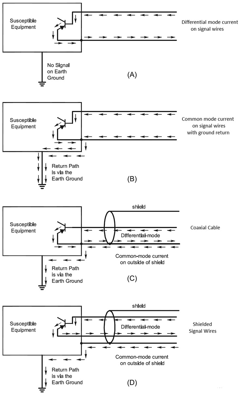
FIGURE 1. Examples of common mode and differential mode signals for different types of cables. A shows differential mode signal current in a two-wire unshielded cable. B shows a common mode signal current with a return path via the enclosure and the earth ground. In C, a common mode signal flows on the outside of a coaxial cable shield with a differential mode signal inside the cable. D shows the differential mode signal on signal wires inside a shield with common mode current flowing on the outside of the shield. (Graphic courtesy of the American Radio Relay League.)
So, doesn’t the shield keep all fields out of the cable? Not really. At very low frequencies — such as AC power at 50/60 Hz — the magnetic fields from a transformer or power line go right through nearly all shields because the material is not thick enough. (See the sidebar on shielding effectiveness.) Even a high quality coaxial cable shield is not enough. Just feed some low-level audio through a piece of coax laying on a power transformer to hear the induced hum. As the frequency gets higher, the shielding becomes more effective, as long as it is connected properly.
How Effective is Your Shield?
A magnetic field is attenuated by absorption as it passes through the thickness of a shield by 8.7 dB for each skin depth of thickness. (See the sidebar on skin depth.) Figure 2 is a graph of skin depth vs. frequency for common shielding materials. The smaller the skin depth for a shielding material, the greater the absorption it provides for a given thickness.
Only magnetic materials can provide magnetic shielding at AC power frequencies. Copper and aluminum thick enough to form a rigid chassis or enclosure begin to provide magnetic shielding around 10 kHz and are quite effective above 1 MHz.
Electric field shielding occurs by reflection, and the loss can be computed by:
R = 20 log [(ZW / 4ZS) cos Φ] dB
where R is the reflection loss, ZW is the wave impedance (377Ω in free space), ZS is the impedance of the shield, and Φ is the angle between the field and the shield.
For common shield materials like aluminum and copper, ZS is <1Ω so even a very thin shield can provide more than 70 dB of shielding. Electric field shielding is quite easy — especially at low frequencies. An electric field shield must be continuous and must completely cover the circuit to be shielded.
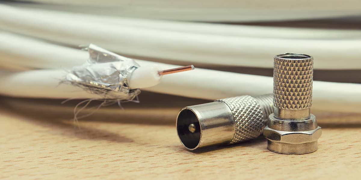
The other common type of shielded cable is coaxial cable with a single center conductor surrounded by an outer conductor (shield), separated by a plastic or air dielectric. Current in coax flows on the outside of the center conductor and on the inside of the shield which is either a tightly woven braid of fine wires, a solid tube of metal (foil or thicker), or a combination of the two. Coax is very effective at shielding the signal flowing inside the cable from outside fields because of its excellent symmetry (which causes the effect of the fields to cancel) and because of the skin effect (see the sidebar) that isolates common mode current on the outside of the shield from the signal inside.
What is Skin Effect?
Because of how AC fields interact with excellent conductors, metals conduct AC only to a certain skin depth, d, that is inversely proportional to the square of the frequency. This is called the skin effect and it decreases the cross-section area of the conductor that conducts AC, increasing its resistance.
d = 1 √ vpfµs
µ is the conductor’s permeability and s is the conductor’s conductivity.
The skin effect begins to have a significant effect above 1 MHz. By 10 MHz, a copper wire only conducts current in its outer 0.02 mm. At UHF and above, a thin layer of metal plating is sufficient.
Shielded Enclosures
The higher the frequency of signals used by a circuit, the more important it is to use a metallic enclosure. Assuming wires and cables going in and out of the enclosure are properly routed and connected, the metal enclosure can keep RF from external fields out and RF from internal signals in. Furthermore, a metal enclosure provides mechanical strength to your project.
Shielding is important for sensitive or important circuits, and to be a “good neighbor” to other equipment that might be disrupted by radiated or conducted EMI (electromagnetic interference). As an example, if you have a general coverage receiver and live in a typical suburban or urban neighborhood, connect a dipole or other antenna and tune to 14.030 MHz — you will hear many weak “birdies” (single tones, often slightly wobbly or jumpy) from Ethernet network equipment being radiated by cables connected to unshielded or poorly shielded equipment. (Computer equipment is notorious for creating and responding to EMI into the UHF range.)
Check out the sidebar that discusses the shielding effectiveness of various types and thicknesses of metal. Figure 2 provides a graph of skin depth for three common metals with frequency.
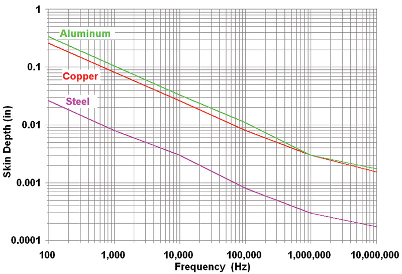
FIGURE 2. Skin depth versus frequency for aluminum, copper, and steel.
As you can see, for all but the thinnest sheet metal, aluminum enclosures are quite effective at shielding above a few kHz. Aluminum is easy to work with and strong.
Other options include building your own enclosure out of printed circuit board material soldered together, bending up some brass or copper sheet, and even spraying plastic enclosures with conductive paint.
Regardless of how good your enclosure is, its effectiveness can be ruined by mismanaging the connections of cable shields. Figure 3 shows how a shield should be connected. Treat the shield as a sort of “RF water pipe” that keeps RF signals inside of the shield and keeps RF currents from external fields out of the enclosure.
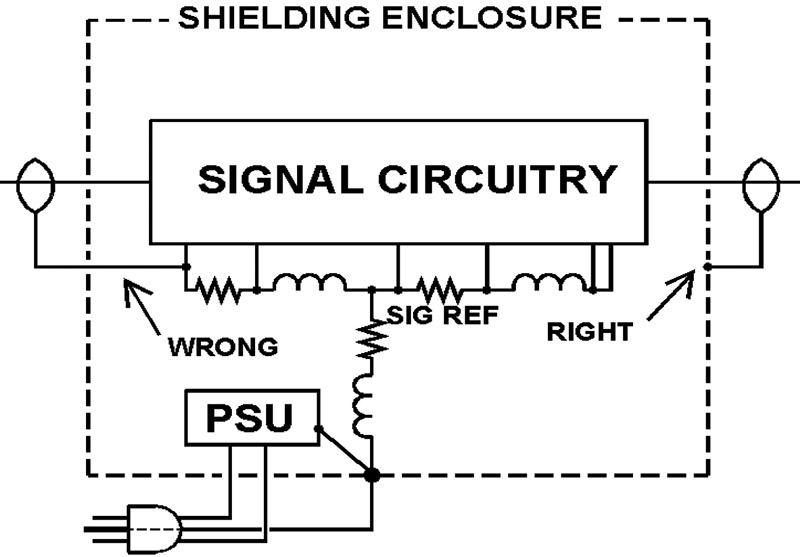
FIGURE 3. The correct and incorrect way of connecting a shield to an enclosure. At the left, bringing the shield through the enclosure allows any common mode current on the shield to couple into the circuit’s signal reference (SIG REF) path. This is a very common source of RF intererence both to and from the equipment. At the right, the shield is connected properly to the enclosure. (Figure courtesy of Jim Brown K9YC.)
NEVER bring a shield through a shielded enclosure. A shield should always be connected to the outside of a metal enclosure. By bringing the shield through the wall of the enclosure, you create a terrific pathway for RF to get in and out. And it will!
NEVER use the shield as a return or ground connection for a signal if you can avoid it. Any common mode current on the outside of the shield will follow the return path to the circuit ground and can wreak havoc. Similarly, any RF noise on the circuit ground will happily escape the enclosure by this same path and radiate to cause RFI.
A lot of audio equipment uses a shielded twisted-pair cable for left/right/common. What should you do if the equipment experiences RFI from external signals? Assuming your equipment has a metal enclosure, use shielded (metal) connectors and be sure there is a good connection between the cable shield and the connector’s back shell.
If the RFI persists, chances are good that one or two cables are providing the path for RF to get into the equipment. Remove all disconnect-able cables and verify the RFI has stopped. Reconnect the cables one at a time until the RFI returns. Add ferrite cores (described here and here Ham’s Wireless Workbench columns) to the cable at the equipment experiencing the RFI. Use a type 31 mix for HF signals and a 43 mix for upper HF and VHF/UHF signals. (Most inexpensive ferrite cores and beads are type 43, but ask the vendor to be sure.) Once you’ve cleared up the RFI from that cable, connect more cables one at a time to see if they need the ferrite treatment too.
What’s the Buzz?
There is a tendency to consider any unwanted low frequency tone in our electronics as “hum,” but more frequently the tone is really a “buzz.” True hum at 50 or 60 Hz is a sine wave created by a magnetic field from AC current or a power transformer. Buzz, on the other hand, sounds harsher with higher frequency components.
If the buzz has a fundamental frequency of 120 Hz, it is almost always caused by insufficiently filtered ripple from a full-wave rectifier in a power supply. If the buzz includes not only the 50/60 Hz tone but many higher harmonics, this is usually the result of improper AC neutral circuit connections or wiring that carries currents with significant harmonic energy known as triplen harmonics. From the tone of the unwanted hum or buzz, you can generally get an idea of its source.
References
I’ve used shielding to scratch only the surface of electromagnetic compatibility (EMC) — a subject that covers all sorts of interference, transients, and noise. If you would like more information on how hams view these and related problems, take a look through the free publications of Jim Brown K9YC. (Figure 3 is from Jim’s tutorial, “A Ham’s Guide to RFI, Ferrites, Baluns, and Audio Interfacing.”) A retired audio engineer and active ham, he has written many papers on dealing with interference. You can find them at www.audiosystemsgroup.com/publish.htm.
Take a look in the “Hum, Buzz, and Interference” section. The ARRL’s tech portal (www.arrl.org/tech-portal) is another great source of know-how to deal with unwanted RF — incoming or outbound! NV
Signals ala Mode
For regular zip cord feeding a speaker, the output signal from the audio amplifier causes current to flow out one conductor and in on the other. This is a differential mode signal in which there is a voltage between the conductors, and currents flow in opposite directions. An external field, however, would induce approximately equal currents or voltages on both conductors, causing current to flow on both conductors in the same direction. This is a common mode signal with current that flows equally on all conductors. (The current would presumably keep flowing from the speaker enclosure through any ground connection and back to the amplifier.)
If the common mode voltages and currents on each conductor are exactly equal, the net effect on equipment in the path of the common mode signal is very small. If there is even a slight imbalance between the conductors, however, that changes some of the common mode signal into a differential mode signal which can affect the equipment. Twisting unshielded zip cord helps maintain balance by insuring that both conductors are exposed to external fields in the same way. Coaxial cable can also be a host to common mode signals on the outer surface of its shield. Even though the signal may not be present on all conductors, it is also considered a common mode signal. These signals can be converted to differential mode signals if the shield connection allows common mode current to enter the inside of the coax. Proper shield connections are very important for equipment connected together with coax.
The “Pin 1 Problem”
In the professional audio industry, the problem of RF interference caused by improperly connected shields was originally identified in a 1994 paper by Neil Muncy. (See the end of this sidebar for the full reference.) This problem was named “The Pin 1 Problem” because pin 1 is the designated shield contact on the three-pin XL-style connectors widely used for microphones and line level audio signals. By demonstrating the nature of the problem — improper connections to the connector’s pin 1 — and how to fix it, “pin 1 problems” in professional audio equipment have been greatly reduced.
Hobbyists are often referred to professional audio and signal-processing literature on RFI that uses the term “pin 1 problem.” You should recognize this as referring to improperly connected shields that lead to RFI caused by common mode RF currents on the shields of connecting cables. The same cures that reduce susceptibility to RFI in audio equipment will work in radio, test, and control equipment too.
The professional audio literature and Audio Engineering Society (AES) standards are excellent sources of information on EMC, with amateurs playing a leading role in their development. Neil Muncy’s paper can be found as “Noise Susceptibility in Analog and Digital Signal Processing Systems,” presented at the 97th AES Convention of the Audio Engineering Society in San Francisco, CA, Nov. 1994.