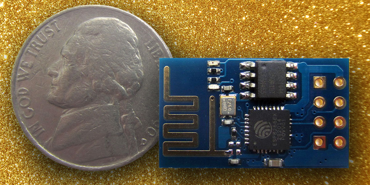
It's not very often that a different piece of hardware comes along and immediately captures the attention of the entire maker community. The Raspberry Pi and the C.H.I.P. are a couple of examples, but the ESP8266 module from Espressif Systems (espressif.com) wins this prize. This little board (PHOTO 1 above) — the ESP8266 module (ESP-01) — is only about the size of a nickel, yet contains a powerful 32-bit microcontroller and a Wi-Fi interface, and it can be purchased for under $10 in single unit quantities
The first projects built with this module all used a microcontroller to control the ESP8266 as a Wi-Fi peripheral using an AT command set over a serial interface. While this was made to work, some of the projects suffered from stability problems as the ESP8266 firmware continued to evolve. Lately, however, a group of enterprising individuals have made the ESP8266 Arduino compatible. This is important for numerous reasons:
- It allows people familiar with the Arduino IDE (Integrated Development Environment) to develop software for the ESP8266 module.
- It allows the software developed in the Arduino IDE to be run directly on the 32-bit microcontroller on the ESP8266 module, eliminating the need (in many cases) for a separate microcontroller altogether.
- It allows the use of numerous third-party Arduino libraries, as long as they don't depend on direct access to the underlying AVR hardware.
Arduino compatibility and the low cost of the ESP8266 are major developments for the Internet of Things (IoT) movement currently sweeping the tech world. Using the ESP8266 allows for very small and inexpensive products to be created that can be controlled and/or monitored remotely.
Note if you plan on putting an ESP8266 module into a commercial product, you will have to pass FCC certification, which can take considerable time and be rather costly.
To understand what a breakthrough this is, consider the cost and size of a traditional Arduino approach to Wi-Fi enabled monitoring and control. First, you have to have an Arduino board (say, an Arduino Uno) from a reputable source which costs between $20 - $30. Then, you have to purchase a Wi-Fi shield for around $20 - $40, bringing the basic system cost to between $40 - $70. Then, consider size. The Uno's dimensions are 2.1” x 2.7”. Attach the Wi-Fi shield and the sandwich is between 1.25” to 1.75” deep and a bit harder to package than the ESP8266 (again, which is the size of a nickel).
Finally, when you consider the ESP8266 has a 32-bit processor which can run at 160 MHz — 10x the speed of the Uno's eight-bit processor — and that it has 512K (minimum) of Flash memory program space to the Uno's 32K, the Uno Wi-Fi solution is looking a little dated.
The Hardware
Actually, the ESP8266 is a whole family of modules which vary in the number of available I/O pins, the amount of onboard memory, the types of interfaces available, and in how the RF antenna is attached/implemented. The module I will be describing in this article (and shown in Photos 1 and 2) is referred to as an ESP-01. This module has its RF antenna etched directly onto the circuit board.
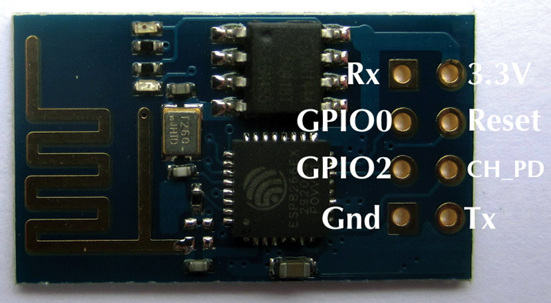
PHOTO 2. ESP8266 (ESP-01) pinout. The squiggly trace is the Wi-Fi antenna. This device has 512K of Flash for program storage.
Information on the whole family of ESP8266 devices is available at www.esp8266.com/wiki/doku.php?id=esp8266-module-family.
The following attributes of the ESP8266 family were extracted from the datasheet (see https://nurdspace.nl/File:ESP8266_Specifications_English.pdf):
- 802.11 b / g / n
- Wi-Fi Direct (P2P), soft-AP
- Built-in TCP / IP protocol stack
- 802.11b mode + 19.5 dBm output power
- Built-in temperature sensor
- Supports antenna diversity
- Off leakage current is less than 10 µA
- Built-in low power 32-bit CPU which can double as an application processor
- SDIO 2.0, SPI, UART, ADC
- Standby power consumption of less than 1.0 mW (DTIM3)
In other words, the ESP8266 family of modules features low power consumption, high RF power output, and is capable of supporting all of the current 802.11 standards required for Wi-Fi connectivity. In addition, it supports many industry standard hardware interfaces and can also function as the application processor in many designs. Note: The ESP8266 is a 3.3 VDC part.
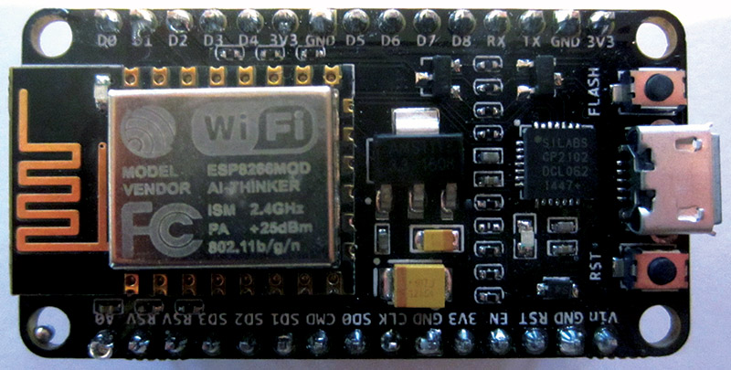
PHOTO 3. An ESP8266 (ESP-12) development module called the NodeMCU Amica with many more I/O pins and memory (4 MBytes) is available. It functions just like the prototype hardware described in this article and is powered directly from the USB port.
Prototyping Hardware
Now that we know something about the ESP8266 module family, let's talk about what we need in terms of hardware to try out the ESP8266 in the Arduino environment. In addition to the ESP8266 ESP-01 module, we need some sort of USB-to-TTL serial adapter, a 3.3 VDC power supply capable of at least 250 mA of output current, a couple of momentary pushbutton switches, an LED, and a 1K and a 10K ohm resistor. Do not skimp on the power supply for the ESP8266. It requires quite a bit of current, and lack of sufficient current will cause the ESP8266 to appear flakey or not work at all.
When I received my ESP8266 modules in the mail, I was anxious to try them out but I didn't yet have the required USB-to-TTL 3.3V serial interface cable to proceed. Since necessity is the mother of invention and since I am not known for being a patient person, I decided to use an Arduino Uno board I had for this purpose. Note, I removed the processor from the Uno as it was not needed.
The breadboard is shown in Photo 4 and the Fritzing schematic is in Figure 1.
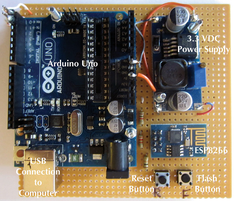
PHOTO 4. Prototyping hardware using an Arduino Uno. This method is not recommended, but works.

FIGURE 1. Prototype hardware using an Arduino Uno as a USB-to-TTL serial converter.
Here, the 5V output of the Uno was used to drive a small switching mode power supply set to 3.3 VDC which, in turn, drives the ESP8266. The Tx and Rx signal from the Uno were connected directly to the Tx and Rx connections on the ESP8266. Yes, Tx to Tx and Rx to Rx. Remember, the ESP8266 is a 3.3V part and that direct connection to the 5V logic levels of the Uno should be avoided. With that being said, this prototype worked perfectly. I have since heard the ESP8266 has 5V tolerant pins but I have yet to have that claim substantiated. Anyway, I figured I only had a few bucks tied up in the ESP8266 part so if it blew, oh well. As it turned out, this prototype worked splendidly.
The Reset pushbutton on the prototype pulls the reset pin on the ESP8266 low, thereby resetting the device. The Flash pushbutton grounds the GPIO0 pin which places the ESP8266 into firmware download mode. The CH_PD line must be pulled high for new firmware to be downloaded.
After my 3.3V USB-to-TTL serial cable arrived, I removed the Uno from the prototype and connected the cable directly to the ESP8266. This approach is shown in Photo 5 and the schematic in Figure 2.
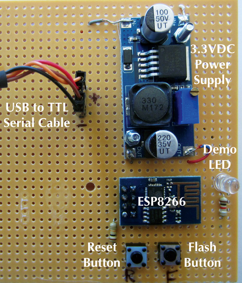
PHOTO 5. Recommended prototyping hardware using a USB 3.3V TTL serial cable. The LED is used for the Teleduino demo.
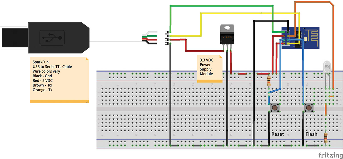
FIGURE 2. Prototype hardware using a USB to 3.3 VDC TTL serial cable. Includes an LED for the Teleduino demo.
Here, the cable provides 5 VDC on the VCC pin which is connected to the 3.3 VDC power supply. The Tx and Rx pins of the cable are at the proper 3.3V interface levels. The Tx pin of the cable is connected to the Rx pin of the ESP8266, and the Rx pin of the cable connects to the Tx pin of the ESP8266. I also added an LED and 1K resistor connected between ground and GPIO2 which will be used with the Teleduino demo described later.
In either case, the following series of steps must be followed to initiate successful loading of code from the Arduino IDE into the ESP8266 module:
- Press and hold the Reset button down.
- While holding the Reset button down, press and hold the Flash button.
- Release the Reset button while still holding the Flash button down.
- Click the Upload button in the Arduino IDE.
- When the sketch starts to load, you can release the Flash button.
Once code is successfully uploaded to the ESP8266, it will be executed every time a power-up or a reset occurs.
Arduino IDE Version 1.6.4
To easily program the ESP8266 as an Arduino, you must use the latest version of the Arduino IDE. As of this writing, that is version 1.6.4. This version has a feature called the board manager which lets third-party vendors add support for their Arduino compatibles that the makers of the IDE don't support directly. Adding support for the ESP8266 is a multi-step process:
- First, you must download version 1.6.4 or newer of the IDE from www.arduino.cc/en/Main/Software and install it. There are versions available for Windows, Mac OS X, and Linux. The installation process is different for each platform, but in each case is pretty straightforward. Follow the directions provided within the installation programs and you should be good to go.
- Next, bring up the Preferences page of the IDE and type http://arduino.esp8266.com/stable/package_esp8266com_index.json into the Additional Boards Manager URLs field. With this completed, click OK.
- Next, go to the Tools menu tab in the IDE, click Board, and then Boards Manager. This will bring up a list of installable items. Scroll down and you should see esp8266 by the ESP8266 Community. Highlight this entry and an Install button should appear. Click this button to install the ESP8266 development software. This can take awhile because a lot of software is being transferred to your computer.
Once this process has been completed, the next time you click the Tools menu and then the Board entry you should be able to select the “Generic ESP8266 Module.” You are now ready to program your ESP8266 as an Arduino. Be sure you make this selection for all of your projects which utilize the ESP8266 module.
In addition, make sure you have a serial port selected in the IDE so the serial monitor can be used. If an appropriate serial port does not show up in the IDE, you may have to install a driver for the USB serial cable you are trying to use.
The Software
With either variety of prototyping hardware in place and the Arduino IDE updated with ESP8266 support, you are now ready to go. Right out of the box you have access to numerous example programs which illustrate some of the ESP8266 module’s capabilities. If you go to File and then Examples in the IDE, you will see these three categories of example programs:
ESP8266mDNS
ESP8266WebServer
ESP8266WiFi
Each of these have one or more example sketches within them. In the ESP8266WiFi category, the following sketches are of special interest:
- NTPClient — shows how to get the time from a Network Time Protocol (NTP) server while demonstrating the use of UDP packets. This is the same technique your computer uses to set its time automatically.
- WifiClient — shows how to use the ESP8266 to talk across the Internet (as a client program) to a server. All client applications will resemble this example program including the Teleduino client discussed shortly.
- WifiScan — lists all of the wireless networks within range of the ESP8266. The network's name, signal strength, and whether or not the network is encrypted is displayed on the serial monitor. The list of networks is updated every five seconds.
- WiFiWebServer — shows how to use the ESP8266 as an HTTP type server. By locally accessing this web server with a browser, an LED connected to the ESP8266 can be toggled off and on. See the example sketch for more information.
Many of these example programs/sketches must be edited before running as you must enter the SSID of your wireless network along with your network's password. Without this information, the ESP8266 will not be able to connect to your wireless network and the example programs will fail.
You may be wondering how much of the Arduino software environment has been ported to the ESP8266 and, in truth, the answer is quite a lot. A list of what is working is available at https://github.com/esp8266/Arduino. This list is definitive as these are the people who did/are doing the Arduino port.
Teleduino
Using the ESP8266 to control an LED or some other device on your local area wireless network is cool but somewhat limiting. What if you want to control your device from anywhere in the world instead? There are multiple ways of doing this — some of which require configuring your modem/router to forward messages through your firewall, opening up the possibility of security breeches. Nathan Kennedy of Kennedy Technology has come up with a better idea that he calls Teleduino.
Teleduino is designed primarily for use with an Arduino with a wired Ethernet shield; there are versions available for Uno and Mega based boards. I was interested to see if I could port some of the Teleduino functionality onto the ESP8266 as an experiment, and with Nathan's help I did so. Go to www.teleduino.org for the details. If you are interested in the full Teleduino functionality on the ESP8266, you will have to wait for Nathan to port the complete code base. If, however, you want to experiment yourself, you can grab my code (TeleduinoClient.ino) from the downloads.
To use the Teleduino code, you must first go to www.teleduino.org/tools/request-key and request an API key. A key will be emailed to you after you provide your name and email address. A key is a long string of hex characters which must be edited into the TeleduinoClient sketch along with your Wi-Fi network’s SSID and password before downloading into the ESP8266. The API key must also be used in all API calls from your browser.
Once the sketch is downloaded into the ESP8266, it will first make a connection to your Wi-Fi network and then it will open a TCP connection to the Teleduino server. Once this connection is made, the ESP8266 will authenticate itself to the server by providing the API key. If you bring up the serial monitor, you will be able to watch this interaction take place.
If all goes well, the Teleduino server will begin sending ping messages to the ESP8266 about every five seconds. Because the ESP8266 establishes an outgoing connection to the Teleduino server, there is no need to open any ports in your firewall and thus create any new security concerns for your network.
To summarize: Once the TeleduinoClient is configured, it automatically connects itself to the Teleduino server when powered up. The Teleduino server translates instructions received over the Internet into actions on the Teleduino device which (in this case) is the ESP8266.
As mentioned, I ported only a (very small) subset of Teleduino functionality. In fact, the TeleduinoClient sketch only recognizes a setDigitalOutput API call, but that is enough to prove the concept workable. On the second prototype shown in Photo 5, I have connected an LED to the ESP8266's GPIO2 pin through a 1K ohm resistor to ground. If I go to my browser and type in (this rather long URL) https://us01.proxy.teleduino.org/api/1.0/328.php?k=<YOUR KEY GOES HERE>&r=setDigitalOutput&pin=2&output=1&expire_time=0&save=0, the LED will turn on. If I try this again but change output=0, the LED will turn off.
Keep in mind that for this demo, the ESP8266 is turning an LED off and on by way of commands entered into a browser which can be located anywhere in the world. If instead of an LED connected to the ESP8266 you connected a solid-state relay (SSR), you could control devices such as a light, a heater, an alarm system, etc. The possibilities are endless.
Want to control your Teleduino device from your Android smartphone or tablet? Check out apps like Teleduino Controller Pro V2 in the Google Play store.
Conclusion
This article doesn't begin to describe the cool things that can be done using the ESP8266. I hope after reading this article you will come up with many ideas for your own projects. I have a few in mind that I may share in future articles if there is enough interest. Please let Nuts & Volts know if you would like other articles about using the ESP8266.
Devices like the ESP8266 make possible the idea of connecting almost anything to the Internet and controlling and/or monitoring them from anywhere in the world. The ESP8266 is a giant step forward in the Internet of Things (IoT) revolution. NV
Resources
The following links provide further information about ESP8266 devices:
Information about the ESP8266 Arduino port can be found at
https://github.com/esp8266/Arduino
An ESP8266 forum full of useful information can be found at
www.esp8266.com
The Espressif forum is available at
http://bbs.espressif.com
The Teleduino client sketch (TeleduinoClient.ino) is available below, in the downloads.
Downloads
What’s in the zip?
Teleduino Client code