It's everywhere! It's everywhere! Fortunately, you can take a bite out of RFI.
RF interference — is it interference to you? Is it interference by you? Possibly both! What does this interference consist of? And how can you tell what type is present? A topic that starts off with so many questions is bound to cover a lot of ground, so let’s get started.
The phenomenon known as RF interference — RFI to its many friends and acquaintances — is a sub-type of electromagnetic interference, or EMI, which is itself a topic that is part of the general subject of electromagnetic compatibility, or EMC. Specifically, RFI involves interference caused by signals propagated wirelessly as radio waves, but even this sub-type of a sub-type of a subject still has a surprisingly subtle and broad reach.
Is RFI Really a Problem?
Undoubtedly. It’s a growing problem beginning to have an impact on the broadcasting and wireless data/telephony industries. Electromagnetic “smog” is pervasive in urban and suburban areas across the entire frequency range, from long-wave signals through microwaves.
The most widespread effect is higher random noise levels all across the spectrum, just as atmospheric smog affects an entire region. This raises the noise floor (the noise present at any frequency), meaning weak signals are increasingly obscured and stronger signals degraded by bits and pieces.
Why would, say, a mobile telephony company care about analog noise since the phones communicate digitally? Because, at some level, just about everything is analog. Inside that phone is a radio receiver looking for analog radio signals from the local base station.
If I mix in a little more noise — let’s say, I raise the noise level by a measly 3 dB at the receiver input — the distance at which the phone’s digital protocol breaks down will decrease by about 30%. That means the coverage area for the base station has decreased by half!
The service provider then has to either build more towers or you have to transmit at a higher power, or both. That’s money out of your pocket, one way or the other. The same is true for stations broadcasting programming, or public safety agency communications.
On a personal basis, most people don’t know (or care) about RFI until their garage door opener won’t work or an audio system starts speaking in tongues. As readers of Nuts & Volts, however, you should become aware of the problem, understand its causes, and know how to solve it. As day-to-day users of the spectrum, ham radio folks are intimately familiar with the symptoms and cures for RFI.
RFI Basics
The definition of RF itself (radio frequency) spans electromagnetic signals over a range of just above audio (about 20 kHz) through infrared light at several hundred THz. To keep this column from occupying the entire magazine, we’ll stay in the range of 500 kHz through the upper end of UHF (ultra-high frequency) around 3 GHz — still a 2,000-fold range.
RFI is discussed as having sources and victims with a path between them. The relationship should be pretty obvious. The goal — paraphrasing Poor Richard’s Almanac — is to “neither a source or victim be.” To deal with RFI effectively, you must be able to identify all three:
- What system or device is creating the interfering signals and how — the source?
- What system or device is being interfered with and how — the victim?
- What is the path by which the RF is radiating from the source and getting to the victim?
Even across the many octaves, the basic techniques to achieve the goal are the same: Keep RF out and keep RF in. The techniques for implementing those two seemingly simple tactics are themselves deceptively simple sounding: Avoid and block.
Differential and Common-Mode Signals
Before digging too deep into cause and effect, we have to understand the two types of signals we’ll be dealing with: differential-mode (DM) and common-mode (CM). Figure 1 shows DM and CM signals for typical unshielded paired wires at A, and a coaxial cable at B. Remedies for DM signals probably won’t work for CM and vice versa.
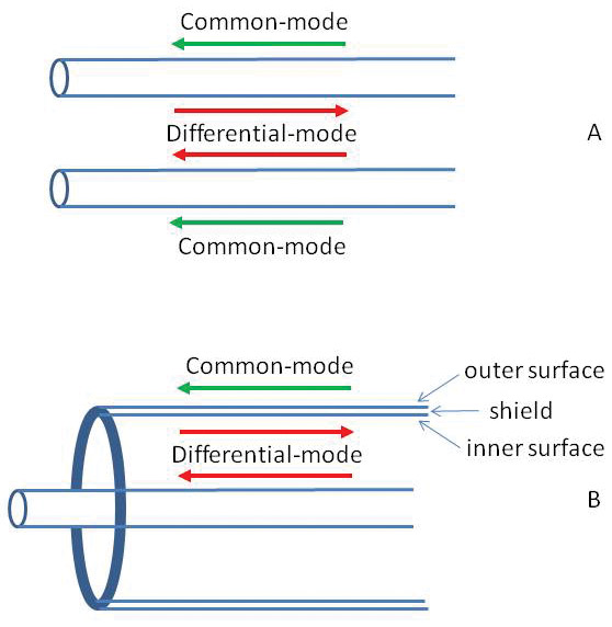
FIGURE 1. Common-mode (CM) and differential-mode (DM) signals can flow on parallel conductor and coaxial cables at the same time without mixing. None of the conductors need to be grounded for RF to pick up and/or radiate RF common-mode signals.
DM signals are what we often think of as “balanced” in that the signal consists of identical currents flowing in opposite directions along two closely-matched paths — neither of which is connected to a ground or grounded enclosure. CM signals flow equally on all conductors of a multi-conductor cable or on the common (shield) conductor of a coaxial or shielded cable.
Taking a close look at Figure 1B, you can see that a single cable can support both DM and CM signals at the same time. In fact, at RF, the outside of a braided or foil shield is electrically independent from the inside! That’s why we use shielded cables — to keep noise and radiated signals from being picked up by the conductor inside the shield.
Why does this happen? The skin effect restricts AC current flow to the outside of a conductor. As shown in Figure 2, at frequencies above 1 MHz, current penetrates copper or aluminum less than 0.1 mm!
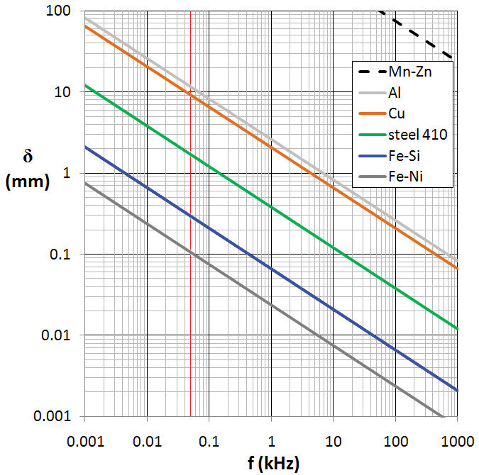
FIGURE 2. Skin depth vs. frequency for some materials. Red vertical line denotes 50 Hz frequency: Mn-Zn, magnetically soft ferrite; Al, metallic aluminum; Cu, metallic copper; steel 410, magnetic stainless steel; Fe-Si, grain-oriented electrical steel; Fe-Ni, high-permeability permalloy (80%Ni-20%Fe).
What Causes RFI?
Interference itself can take a variety of forms. If you are a radio user — as hams are — interference may just be higher noise levels or it can be an actual spurious signal or spur that obscures a desired signal or upsets receiver operation. For example, the harmonic of an intentionally generated signal at an integer multiple of a fundamental frequency can fall on the same frequency as a desired signal thereby interfering with reception.
Spurious signals are a common problem when RF leaks out of equipment due to improper shielding or cabling. Digital signals that transition very quickly between voltage levels are composed of fundamental and many harmonics to generate the sharp edges. The harmonics appear all across the RF spectrum into the microwave region for high speed data. Once radiated, they propagate just like any other intentionally radiated signal.
Switchmode or switching power supplies or power converters are another very common source of spurious signals. These power converters work by “charging up” inductors with magnetic energy, then suddenly interrupting the current to transfer the energy to an output filter capacitor where it is changed to steady DC.
The interruption of current creates a wide spectrum of spurious signals spaced at intervals of the supply’s switching frequency. If output filtering is not designed properly or — in a growing number of instances for imported supplies — not installed at all, the strong spurious signals can disrupt normal communication throughout an entire neighborhood.
Common uses of switching converters include lightweight wall wart DC supplies, battery chargers, electronic lighting ballasts, and low voltage lighting.
Really strong signals can overload a receiver to the point where it causes distortion of a desired signal — even if the signal is completely legal and not in the frequency range being received. This is called fundamental overload and is caused by the receiver’s inability to reject the out-of-band signal. Inexpensive receivers such as wireless phones or portable radios have limited filtering, so are susceptible to this type of interference.
Maybe a receiver isn’t involved at all and the interfering signal is simply so strong that it disrupts the proper operation of an electronic device. We can refer to this as common-mode breakthrough, where the interfering signal is picked up by cables and carried to internal electronics where it is strong enough to alter circuit functions.
It is also common for unshielded electronics in plastic boxes to pick up and be disrupted by strong signals without any cables at all! This is direct detection and it can require modifications to the circuit to eliminate the interference.
The general process for assessing which types of RFI one is dealing with is outlined in the steps of Figure 3. There are different remedial techniques for each. Using the wrong technique or applying it to the wrong end of the path won’t solve the problem.
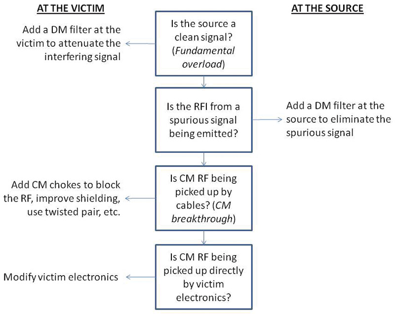
FIGURE 3. The general process of identifying the source and type of interfering signal. Use the appropriate DM or CM remedy at the “victim” or “source” as indicated.
Keeping RF In
At a potential source — such as digital computer and networking equipment, microprocessor-controlled appliances, switching converters, any circuits that turn large currents on and off — the first step is to avoid radiating RF if you don’t have to. This is not just being altruistic, because if your system is radiating RF it can also receive RF by the very same path. Closing off that path to outbound RF usually closes it to incoming RF, too! It’s just good engineering to do that right in the design.
A good strategy to follow is to be sure your printed circuit board (PCB) has filtering applied to any signal or power connection entering or leaving the board. For example, a 0.01 µF disc ceramic capacitor to circuit common on a low frequency signal or control lines and power connections will act like a short-circuit at RF. That path will be “cold” at RF for both incoming and outgoing RF signals. (Note that any component connected directly to the AC line must be “line rated” to avoid fire hazards.)
Treat your equipment as if all of the signals going in and out of it were water, and every connection had to be water-tight. Start with a metal enclosure — even for simple projects. Using a plastic box means you have two strikes against you RF-wise: You have no shield that will route noise and RF currents away from the circuit, and every wire and PCB trace in the electronics will act as an antenna.
Use shielded cables and connectors — including a shielded AC power connector — with the shield connected to the enclosure.
Another often overlooked strategy is to avoid connecting the circuit common to any conductor that will leave the enclosure without being inside a shield. Keep the circuit common connected to the shielding enclosure as a separate connection from any data or signal cable as shown in Figure 4. (Refer to the sidebar, “What is the Pin 1 Problem?”)
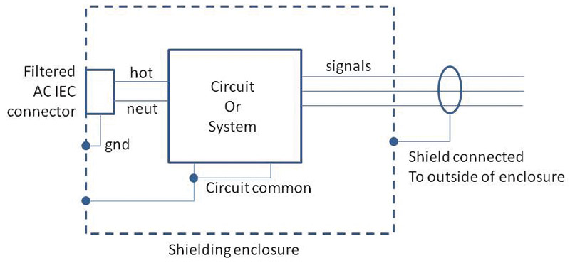
FIGURE 4. For RF immunity and to avoid radiated RF, electronics should be constructed inside a conductive enclosure such as aluminum. Connectors should be shielded, with the shield connected to the outside of the enclosure.
What is the Pin 1 Problem?
In the pro audio world, the “pin 1 problem” was identified by Neil Muncie in 1994. It is caused by the shield pin of the ubiquitous XLR connector (pin 1) being attached directly to circuit common. This connection provides an RF highway for signals being picked up on the cable’s shield directly into the equipment where they can cause interference. Simultaneously, any noise or spurious signals present on the circuit common are given a terrific antenna to radiate from.
The Mackie Company — a professional audio equipment manufacturer — has addressed this in the application note, “Grounds, Shields, Hums, and Buzzes.”
More information is available in several papers and tutorials by Jim Brown K9YC (a retired professional audio engineer) on his website at http://audiosystemsgroup.com/publish.htm.
Keeping RF Out
Let’s say the RFI is being caused by a receiver — such as an over-the-air TV receiver or scanner — by fundamental overload from an otherwise legitimate signal.
For example, you might live across the street from the local TV and FM antenna tower — somebody has to! The strong signal is probably coming right in the antenna input of the receiver, along with the signals you want to hear.
In this case, you can block the unwanted signal with a DM filter in the antenna input cable. The goal is to reduce the level of the signal you don’t want until it is weak enough for the receiver to reject.
To do this successfully, you’ll need to know the frequency of the signals you want and of the signal you don’t want. If the unwanted signal is at a higher frequency, you can use a low-pass filter to allow the signals you want into the receiver while blocking the higher frequency unwanted signal. A high-pass filter does the opposite.
In some circumstances, you might have to use a band-pass filter that only allows some frequencies through while blocking all others. Remember that if the unwanted signal is on the same frequency as the one you do want, no filtering is possible. You’ll have to figure out how to get rid of the interfering signal at the source.
In the previous article, I talked about ferrite cores and beads, and how great they were for suppressing RFI. Ferrite chokes — placed at the right location in a system of electronics — can do wonders at blocking CM signals getting into your system on the shields and common-mode paths of wiring and cables.
Figure 5 shows a typical computer in which any piece of equipment can be generating and receiving noise — a distressingly common situation — with recommended locations for the chokes.
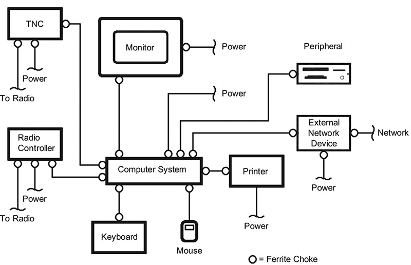
FIGURE 5. The use of ferrite chokes in a computer system where any piece of equipment can either be an RFI source or RFI victim. Ferrite chokes should be placed as close to the equipment as possible. Graphic courtesy of ARRL.
Ferrite chokes consist of a clamp-on core or a toroid with cables or wires wound on them. Don’t be satisfied with just passing a wire through a core once. Wind as many turns on the core as you can to increase the impedance created by the choke.
Remember from the previous column that ferrite impedance changes with frequency, so be sure to use the right type or mix of ferrite. If you are mostly concerned with RF below 30 MHz, use a type 31 mix ferrite.
For higher frequency signals, use type 43. (The various recommendations are covered in the Fair-Rite catalog, available online at www.fair-rite.com.)
More About RFI
I’ve just barely scratched the surface of a topic to which engineers devote entire careers! You may just want to get rid of some interference or keep a system from interfering with some other system. Or, maybe you are designing for reliable operation — good for you!
Hams have been dealing with RFI since the first transmitter was built, so you can find a great deal of useful references on the ARRL’s RFI website for hams at www.arrl.org/radio-frequency-interference-rfi. Jim Brown’s tutorials mentioned in the sidebar are good, and there is an excellent chapter on RF interference in the ARRL Handbook’s recent editions.
Design for EMI quality — to keep the RF both in and out — at the outset of building your system. You won’t regret it! NV
Cable System Leakage
Cable TV systems carry signals from the very low MHz to upper UHF, so extra attention has to be paid to the details of making proper connections. This keeps the cable system’s programs noise-free, and also prevents the signals getting out and causing interference. The cable TV channels are not restricted in frequency like over-the-air TV, so the signals can be directly on top of other over-the-air signals. This is known as cable leakage and is most often due to loose, dirty, or improperly installed type F connectors on the cable feed. If you experience interference to or from your cable TV equipment, making sure connectors are tight, clean, and properly installed is a great place to start looking for problems.