Are you reading this on a tablet? The tablet depends on its built-in antenna for Wi-Fi connectivity, transferring files back and forth from another PC, or to use one of the many mobile phone networks blanketing populated areas. Even in the miniature flattened volumes that are the norm for today’s wireless communication equipment, there has to be an antenna. It might be hidden, it might be tiny, but it’s there. Knowing about common antennas is a good step toward effective data link (and other wireless) system design.
Dipole Basics
A while back, I discussed how to build a simple ground-plane antenna from a BNC connector and some lengths of wire. The ground-plane is basically “half a half-wave dipole,” so let’s back up a little bit and review the dipole. As the fundamental element at the root of many antenna designs, understanding the dipole places you on solid ground.
When referring to a dipole, the usual assumption is that the dipole is a thin conductor (like wire or rod), one-half wavelength (1/2 λ) long at the frequency being used, and that the feed line is attached in the center (a.k.a., “center-fed”). In fact, “dipole” is constructed from “di” (two) and “pole” (polarities) which describe the signal’s effect on the dipole: The polarity of the voltage between the ends of the dipole reverses every half-cycle, causing current flow to reverse as well, sloshing back and forth along the dipole. Voltage is maximum at the ends of the dipole, and current is maximum in the middle as illustrated by Figure 1.
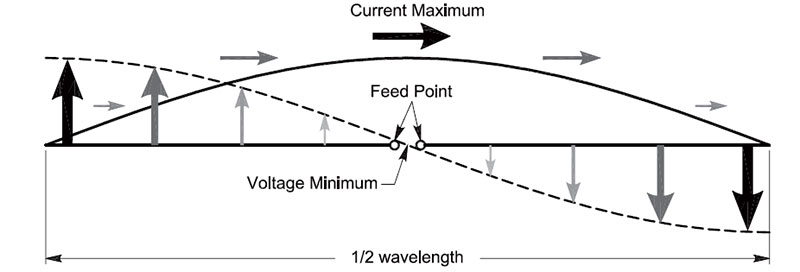
FIGURE 1. Current and voltage distribution along a half-wave dipole. (Graphic courtesy of the American Radio Relay League.)
The dipole radiates a signal caused by the electrons that make up the current being constantly accelerated or decelerated in response to the AC voltage created by energy from the feed line. In fact, radiation of electromagnetic (EM) waves only occurs when electric charge experiences positive or negative acceleration. (In radio and electronics, the charges are electrons but they could be anything with an electric charge.)
The strongest radiation of EM waves results from charge being accelerated along a straight line (like the dipole conductor); it is strongest at right angles to the flow of the charge. This results in the classic “figure 8” pattern of the dipole’s radiation as shown in Figure 2.
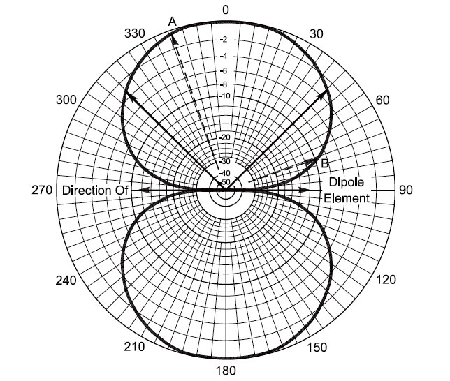
FIGURE 2. Radiation pattern of a half-wave dipole in free space shows the strongest signal radiated and received broadside to the dipole’s axis. Distance from the origin to the solid curve represents signal strength in dB with respect to the maximum. The solid arrows at 45 and 135 degrees show the points at which signal strength is reduced by half (-3 dB).
(Graphic courtesy of the American Radio Relay League.)
A physical dipole is a little shorter than the half-wavelength of an EM wave traveling in “free space,” meaning away from any conductive or refractive material. This is due to the effect of the wave traveling along the surface of the dipole’s conductor, called the antenna element. As the element is made thicker (larger wire, thicker rod, wider strip, etc.), the shortening effect gets stronger. You may see the equation length (in feet) = 468 / frequency (in MHz), but that is only applicable at relatively low frequencies (below 20 MHz), and for thin wire dipoles within a half-wavelength of the ground.
If you're building a dipole, determine the element dimensions by using an antenna modeling program that can account for this effect, use published lengths for a proven design, or be prepared to test and trim until you get the results you want.
Antennas Work Coming and Going
Regarding the radiation pattern in Figure 2 — does it describe the antenna’s transmitting characteristics or receiving? It describes both!
Nearly all antennas are bilateral, meaning they behave the same for transmitted or received signals. This ability requires the antenna to not contain any non-linear materials such as some ferrites or magnetic materials. The antenna must also be operated at power levels that do not cause the antenna materials to operate non-linearly, such as from arcing or saturating.
Radiation?! Eek!
The word “radiation” tends to freak people out. In wireless, the radiated energy is non-ionizing and unable to liberate an electron from its host atom which would lead to chemical changes and, eventually, genetic damage. Electromagnetic radiation has not been shown to have any effect on living tissue except to heat it up — called “thermal effects.”
The term “radiation” is just used as a generic term for “giving off energy.” The frequency of the EM waves would have to be very, very, very much higher than radio frequencies — even microwave — before it would be of concern.
Ultra-violet rays that cause sunburn are at about the lowest frequency (longest wavelength) for which genetic damage would occur, and thus present a cancer risk. Wireless communication waves are many orders of magnitude less energetic and thus pose no such threat.
Yagi Antennas
Take a look above public safety agency stations, weather stations and tide gauges, government buildings, and so forth, and you’ll see small antennas with several parallel elements made from aluminum rod. Wi-Fi and mobile phone “extender” antennas look the same as well, with numerous short parallel elements arranged along a central support (called a boom). These are Yagi (pronounced to rhyme with “baggy”) antennas; more properly called Yagi-Uda arrays after the antenna’s two inventors, Drs Yagi and Uda from the University of Tokyo.
Developed in the mid 1920s, the Yagi antenna has been a mainstay of HF, VHF, UHF, and microwave wireless communication ever since. (While Dr. Uda [“oo-dah”] was the primary inventor, his partner, Dr. Yagi could speak English and so became more closely identified with the antenna during a series of lectures introducing the design.)
The Yagi is a parasitic array, meaning that only one of the elements (the driven element) is actually connected to a feed line and the rest interact with the radiated EM waves. Each element is very similar to a dipole, but if you look closely, you’ll see that the elements get longer toward the “back” of the antenna (the non-preferred direction) and shorter toward the “front.”
The driven element is usually just a few percent shorter than an independent half-wavelength dipole. Elements in back of the driven element are called reflectors, and those in front of the driven element are called directors.
The non-driven elements interact with the signal radiated by the driven element — an effect called mutual coupling. Coupling means that the elements exchange energy by picking up and re-radiating signals. The re-radiated signal is also picked up and re-radiated by the other elements again and again. The coupling between elements, the spacing between them, and the effect of the element lengths on current in elements combine to reinforce signals toward (or from) the front and reject signals toward (or from) the back. This creates a “beam” antenna with a preferred direction for receiving and transmitting, which is called “gain” as explained in the sidebar.
What is Antenna Gain?
When a designer says a beam antenna has a gain of some number of dB, what do they mean?
First, the antenna does not create energy, it merely focuses it. Like a parabolic mirror, it does not generate light; it only reflects it in such a way as to concentrate it. Gain antennas do the same.
Imagine the isotropic antenna that radiates and receives equally in all directions. Its radiation pattern is a perfect circle. This antenna does not exist in practice, but is a useful mathematical reference.
Imagine the isotropic antenna’s three-dimensional pattern as a round balloon with the air representing the radiated signal. A directional antenna “squeezes the balloon” so that the signal is suppressed in some directions and enhanced in others. It does not “create” energy — it merely redistributes it.
The comparison between the directional and isotropic antennas is measured in dBi — decibels with respect to an isotropic antenna which forms the reference for the calculation of dB. An antenna with 3 dBi of gain will transmit or receive a signal 3 dB stronger than an isotropic antenna in that specific direction.
Another common reference antenna is the dipole, and gain (with respect to a dipole) is measured in dBd with the reference being the dipole’s maximum free space gain broadside to the dipole as shown in Figure 2.
Figure 3 shows a three-element Yagi used for portable operation in direction finding. (For more information on these popular activities, see en.wikipedia.org/wiki/Amateur_radio_direction_finding.)

FIGURE 3. A three-element Yagi antenna made for portable direction finding use. The antenna consists of a reflector (left), driven element (middle), and director (right). This antenna has approximately 5 dB of gain in the forward direction (to the right) compared to the maximum signal radiated by a dipole. (Graphic courtesy of the American Radio Relay League.)
This particular antenna’s elements are made from metal measuring tape so they can flex and bend without damage. You can clearly see the reflector at the back, the driven element in the middle, and the director element at the right. Figure 4 shows the radiation pattern typical for such an antenna.
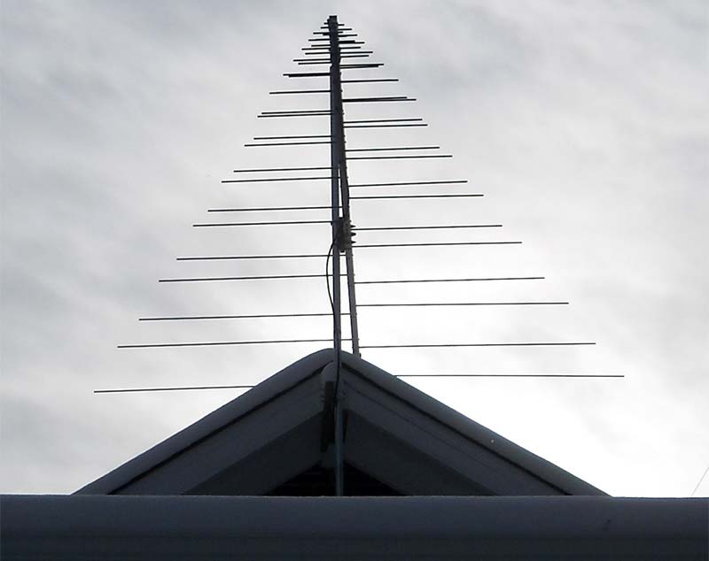
FIGURE 4. The T-28 log-periodic by Tennadyne covers 50 to 1,300 MHz. The 12 foot boom consists of a pair of square tubes that act as the feed line for the antenna.
Yagi antennas with a dozen elements or more — creating a very narrow beam — are not uncommon for frequencies above 100 MHz. At lower frequencies, the longer elements and boom require more robust construction materials and techniques.
The Biggest Yagi
The largest single amateur radio antenna ever built was a three-element behemoth Yagi for the 160 meter band (1.8 MHz) by the Finnish club, Radio Arcala, OH8X (vk6ysf.com/Radio_Extremes.htm). It had elements 59 meters long atop a 100 meter tower, and a boom so large a small car could be placed inside of it.
Compare that to a Yagi for Wi-Fi with the longest element approximately 6 cm long! Yet, the antennas operate on exactly the same principle of re-radiation and reinforcement.
Hams have a saying that, “If it stayed up last winter, it’s not big enough!” Well, the OH8X Yagi was certainly big enough, and unfortunately validated the saying by collapsing in the winter of 2013. Ironically, it was not the antenna that failed, it was the supporting tower!
If you would like to experiment with a Yagi antenna to improve your TV reception, pull in a distant FM station, or maybe extend the range of a 900 MHz data link, you can do so inexpensively by building the antenna yourself. Kent Britain WA5VJB has developed an entire line of Yagi antennas that can be constructed from nothing more than spare copper wire and a piece of 1x2 lumber. Kent’s “Cheap Yagis” website (www.wa5vjb.com/yagi-pdf/cheapyagi.pdf) provides all the details.
Log-Periodics
You may be thinking, “Ah hah, so my outside TV-FM antenna is a Yagi!” Not quite. While common TV antennas look like a Yagi, closer inspection shows that the dipole elements are bent forward in shallow vees and the feed line is connected to every element in a criss-cross pattern down the length of the array. This type of antenna is a log-periodic dipole array (LPDA, or more commonly, a log-periodic or just plain “log.”
Figure 4 shows a log-periodic antenna for 50 MHz through 1,300 MHz mounted above my house (the antenna elements are all horizontal — the antenna is not pointing at the sky).
The log-periodic’s name comes from the logarithmic spacing and length of the elements; it is defined entirely in terms of angles, such as the taper of the triangle surrounding the elements. The active region of the antenna “moves” back and forth along the array as the frequency changes. The dipole elements closest to the frequency of the signal radiate it or transmit it while the other elements remain electrically inert.
With a sufficient number of elements, a log can cover a very wide range of frequencies with consistent performance — even on the shortwave HF (high frequency) bands from 3-30 MHz. In fact, these antennas are popular with government and military stations because only one large antenna is needed to operate effectively on several bands instead of several dedicated antennas.
More Antenna Resources
The ARRL (American Radio Relay League) offers a lot of information on antennas to the public via the Technical Information Service (www.arrl.org/radio-technology-topics) and on the Tech Portal page (www.arrl.org/tech-portal) with links to third-party vendors and amateur reference sites. We’ve just scratched the surface of the world of antennas — these sites will help you learn more.
Inverted-F
One of the most popular antennas for wireless devices is the Inverted-F illustrated in Figure 5.
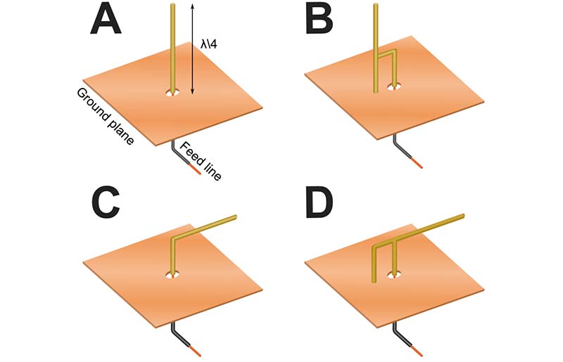
FIGURE 5. The Inverted-F antenna is a modified ground-plane (A) with the feed line connected at a point with the desired impedance (B). If the antenna is bent over the ground-plane at right angles (C), the feed point can still be attached away from the base (D) to provide a good impedance match. (Graphic courtesy of Spinningspark at Wikipedia.)
The mobile device and Wi-Fi band at 2.4 GHz has a wavelength of approximately 12.5 cm, so a 1/4-wavelength ground-plane antenna would be about 6.25 cm (2.5 inches) long. Even though this is small, it is still too big to be convenient for a phone or other pocket-sized device. As shown in the figure, though, the antenna can be bent over and is less than 1 cm above the ground plane at 2.4 GHz.
This is a much more manageable proposition for phones and similar items. Freescale Semiconductor’s application note “Compact Integrated Antennas” shows typical inverted-F designs and variations on that theme.
Patch Antennas
Most people think an antenna has to be a wire or tube or rod. Not so! The antenna is only a convenient structure on which current can be made to flow and create the desired radiation pattern. It is the currents that radiate and receive signals, not the conductor on which they are flowing.
The patch antenna (and its relative, the slot) is a good example of such an antenna. Figure 6A shows a photo of two patch antennas used on the amateur 23 cm band near 1,300 MHz.
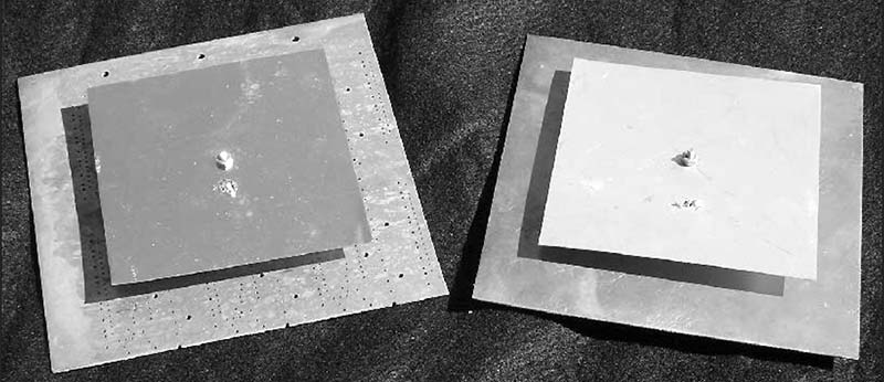
FIGURE 6A. The patch antennas shown here are designed for the amateur 23 cm band and are made from sheet metal (left) and PCB material (right). The basic design information for the antennas is given at B. Polarization is determined by the orientation of the feed point.
The feed line is attached a small distance from the center of the patch and a bit above an underlying ground plane as shown in Figure 6B.
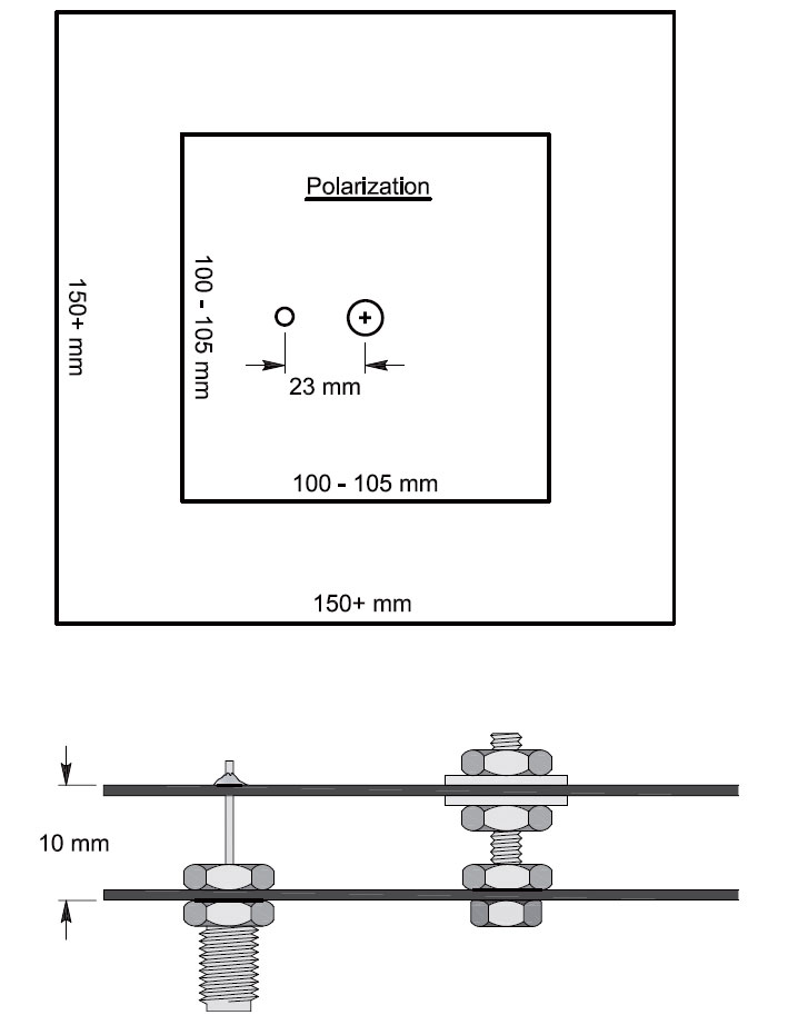
FIGURE 6B.
Energy from the feed line excites the entire patch surface, resulting in regions of maximum current. The resulting current patterns create a pattern similar to two parallel dipoles with their currents in-phase and spaced by approximately 1/2 wavelength. This creates 2-3 dBi of gain in an omnidirectional pattern above the patch ground plane. Sheet metal or the copper on a printed circuit board can be used so it’s easy to see how this type of antenna might be a good choice for a thin flat electronic device!
The Operator as an Antenna
At the start of this article, I suggested that the wireless device user could be an antenna, too, and that’s just what happens with a handheld VHF or UHF transceiver such as the popular Family Radio Service (FRS) units. The stubby “rubber duck” antenna provided with the transceiver is a ground plane antenna. So, where is the ground plane?
The case of the radio — if metallic — does some of that work, but it’s not really big enough to do the job all that well. If the radio’s case is plastic, then there is no ground plane at all! Or, is there?
Your hand wrapped around the body of the radio makes a very good capacitor, coupling strongly to the radio case or the internal electronics. RF at these high frequencies will flow through that capacitance to your skin and then along the surface of the skin for quite a distance.
Current flowing on a surface radiates and receives whether the surface is metal or a concoction of salt water and protein such as you! While your skin is pretty lossy, that extra antenna surface can make a big difference in communication range.
Can you hear me now? NV
The Antenna Book – An Affordable Reference
I don’t know about you, but the last time I checked the price on a professional-level or college-level antenna reference text, my wallet just about had a heart attack! Luckily for amateurs and hobby-level antenna users, there is a kinder, gentler antenna reference that won’t break the bank for a new copy: the venerable ARRL Antenna Book, now in its 24th edition (https://home.arrl.org/action/Store/Product-Details/productId/114288).
It covers a lot of background theory including propagation and transmission lines, as well as presenting a wide variety of practical designs and construction details. Many professional engineers have a copy on their desks as a go-to reference, as well.
If you need the detailed engineering specifics, you can always move up the ladder to the professional books, but the Antenna Book will get you started at far less expense.