I suspect that for many of you the name Numitron is new, while for many others it will bring back (hopefully fond) memories. The venerable electron tube (a.k.a., thermionic valve) has all but disappeared from the mainstream electronics world, and along with them related old technologies such as the Nixie tube (featured in previous N&V articles), Dekatrons, Numitrons, and Panaplex displays, and (to a lesser extent) Vacuum Fluorescent Displays (VFDs) have also faded into the background.
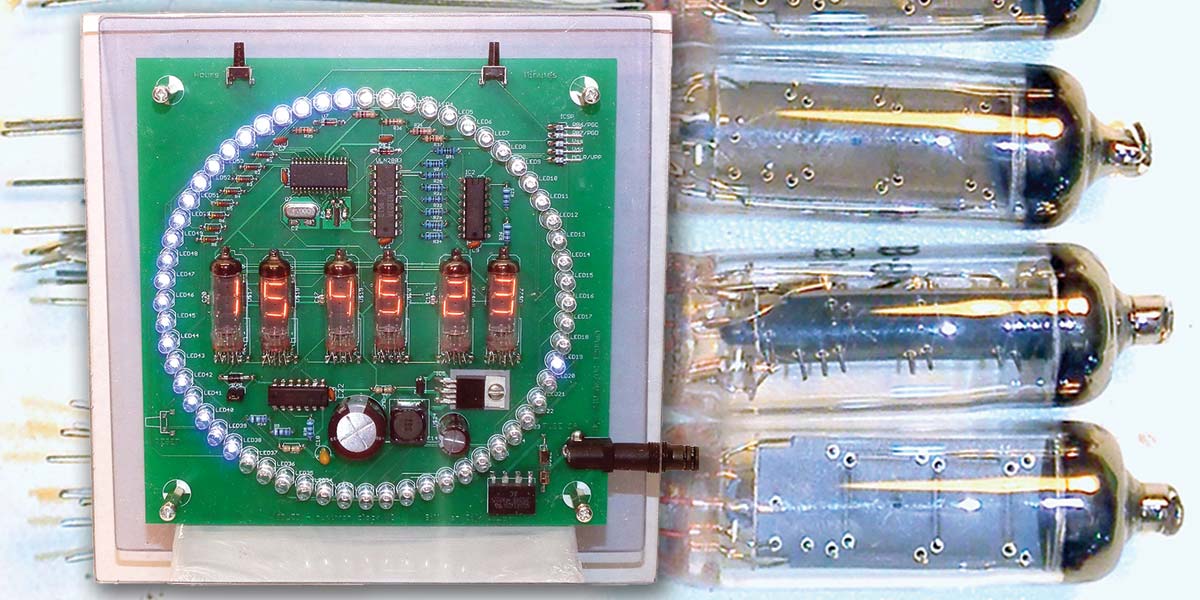
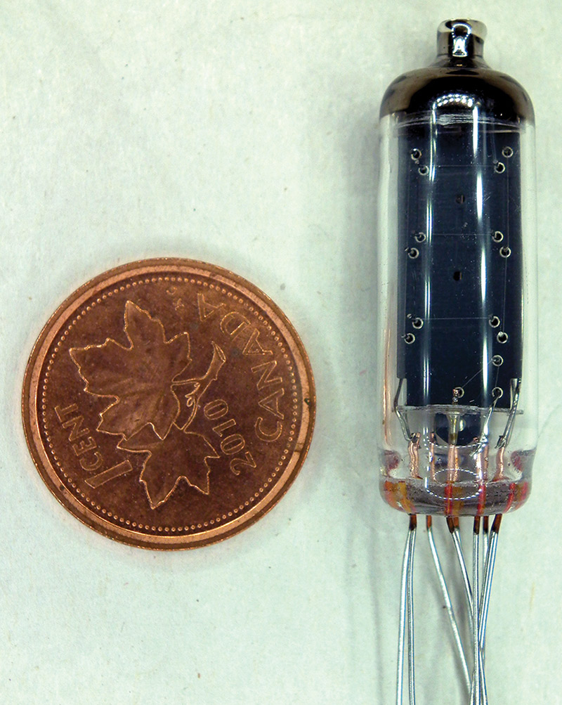
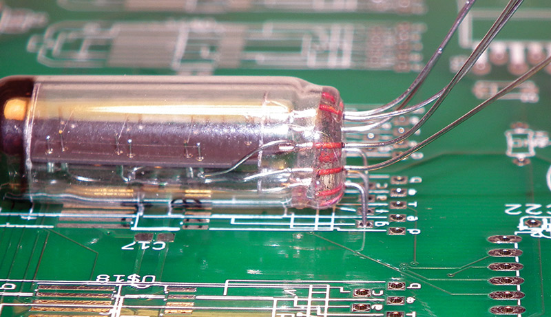
This particular project was designed to showcase Numitron tubes (Figure 1), which are still available for a reasonable cost on eBay from old Russian cold war stock. As stocks (rapidly) dwindle, their cost increases steadily until they will be gone forever. Don’t miss out on this opportunity to build a useful project showcasing this beautiful cold war era component.
FIGURE 1. A Numitron tube (with a penny for scale) ready to install.
The Numitron had an early advantage: At that time, they were slightly brighter than LEDs of those days, and did not have a great dependence on ambient temperature. Nixies, Panaplex displays, and later LCDs required heating elements when used outdoors in colder regions. Even today, the Numitron is still regularly found working in older gasoline pumps.
The Numitron is still a vacuum tube, and the wires of the IV-9 pass via a sealed hole through the glass envelope. Great care must be taken to ensure no stress (from bending or soldering) is transferred to the glass, which may cause it to crack.
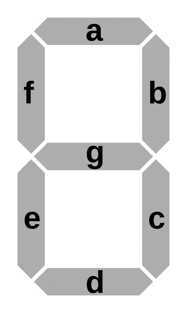
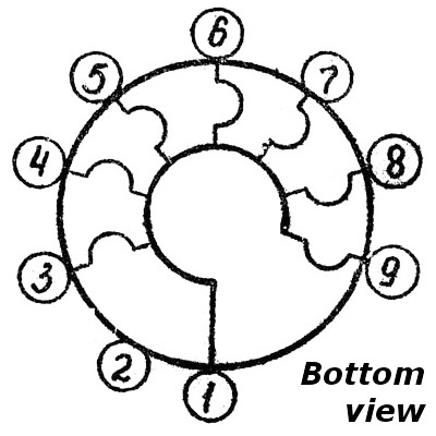
The Numitron is not a traditional tube (valve) in that there is no electron emission involved; it only has filaments, and as such is more analogous to the light bulb than any other electrical device. Seven small filaments (Figure 2a) are arranged in the traditional formation of the seven-segment LED numerical display we are all familiar with (Figure 2b), all within a simple glass tube.
FIGURE 2a. A typical seven-segment display layout uses letters to identify each individual lighted part of the display.
FIGURE 2b. The pinout of a Numitron tube. Note that since the Numitron uses filaments, the common can be positive, negative, or even power via AC voltage.
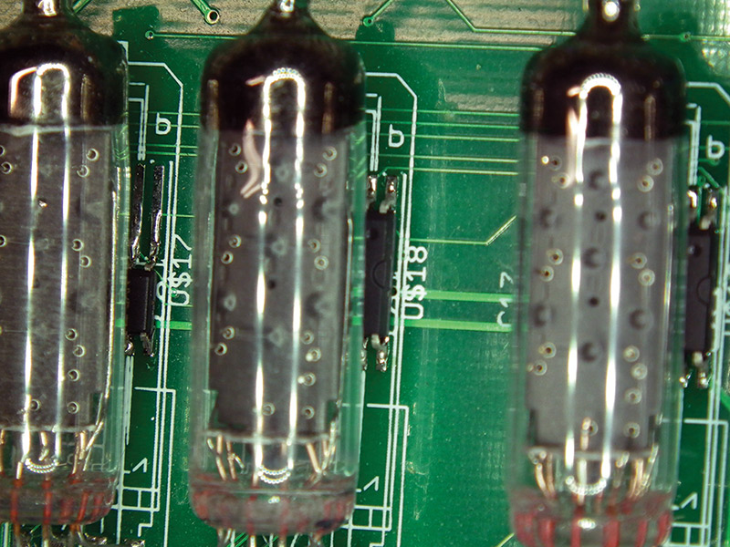
The particular Numitron used in this project (the IV-9) operates on five volts at about 23 mA per segment. It has “fly leads” and as such does not require a difficult socket (Figure 3).
FIGURE 3. The Numitron tube mounts directly to the PCB without the need for a socket.
The Project
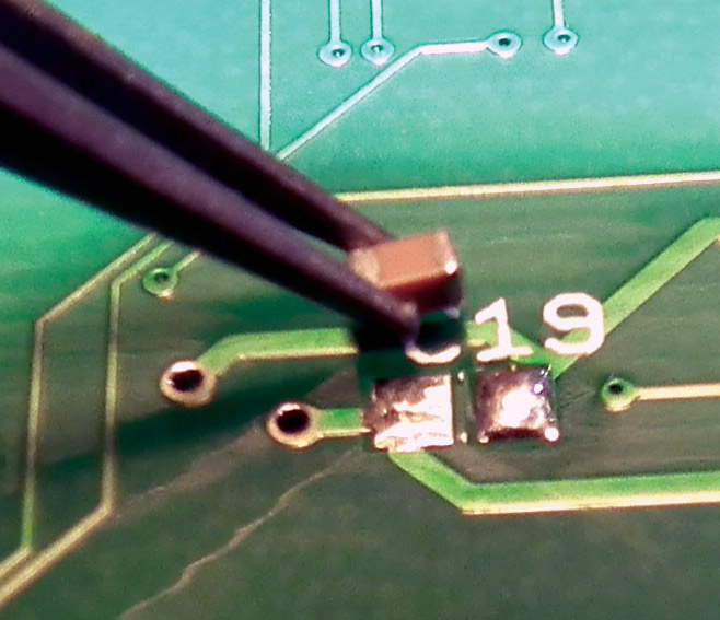
In order to effectively showcase the Numitron, I wanted to do it in a useful as well as attractive way. I also wanted to integrate it with more modern technologies — a hybrid as it were — and use as many parts possible that I had in stock. I love challenging my soldering iron, so SMDs (surface-mount devices) were used as well (Figure 4).
FIGURE 4. Close-up of placing one of the 0805 caps on the board.
The “brains” of the project is a Microchip PIC, and it is a very busy fellow in this project; it’s in control of everything happening on the board. LEDs lend themselves very well to multiplexing, and that is used extensively to control the 60 LEDs that form the circle around the Numitrons. They display eight different programmed patterns, most based on a one minute repeat cycle.
The Numitrons, on the other hand, do not lend themselves at all to multiplexing, and therefore a BCD decoder (with latch) was used to drive each tube. I’ll explain more about the operation of those later on. The schematic and board were created in Eagle, and the files are available for download at the article link in native Eagle format as well as the Gerber RS274x format.
The PIC
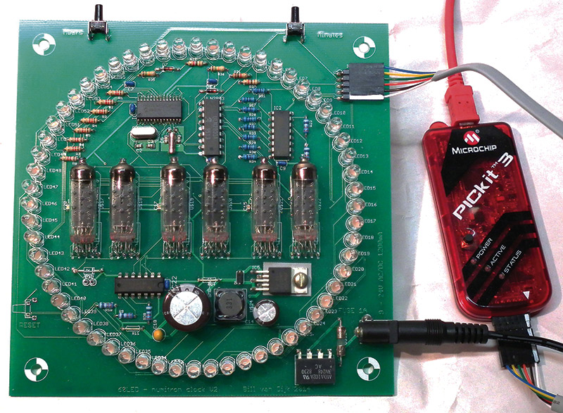
Programming of the PIC is done through the ICSP connector located on the board. I use the PICkittm3 combined with MPLAB IPE (integrated programming environment); refer to Figure 5. Other options are available for programming, although programming SMD devices off-board often requires a special adapter. The main system crystal frequency is 4 MHz. The clock (time) crystal is a small 32 kHz watch crystal. NOTE: This is a critical part for clock accuracy! Please resist using an unknown or salvaged part here.
FIGURE 5. The PICkit3 connected to the Numitron board for programming.
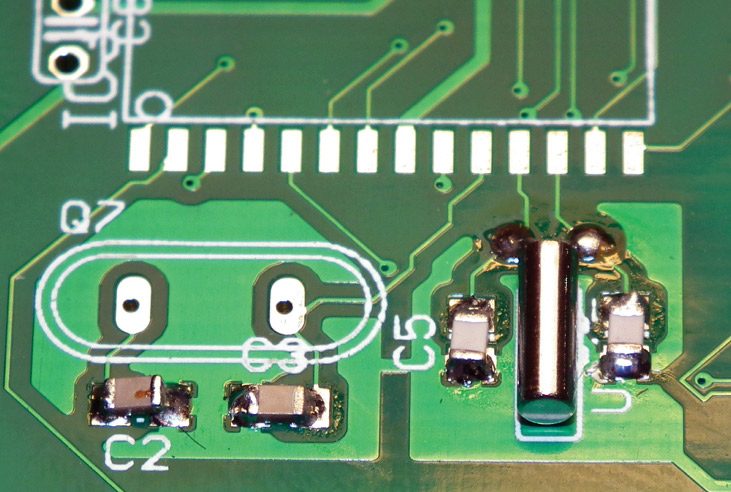
The two 12 pF load capacitors (Figure 6) determine its frequency accuracy, and must be matched with the part. Accuracy of one second per day or less is possible if the crystal and load capacitors are properly matched. If you use a different crystal than listed, be sure to change the load capacitor values to the specification of your part.
FIGURE 6. The clock timing crystal installed on the PCB with the surface-mount noise decoupling capacitors.
A 0.1 µF ceramic capacitor is placed close to the PIC (as well as the other chips) to provide noise decoupling. After all, there is a lot of heavy duty switching happening on this board. The reset button is not debounced (not needed), and for all intents and purposes may be left off the board all together. Simply disconnecting and reconnecting the power will do the same, and prevent non-intentional reset when in use.
The Power Supply
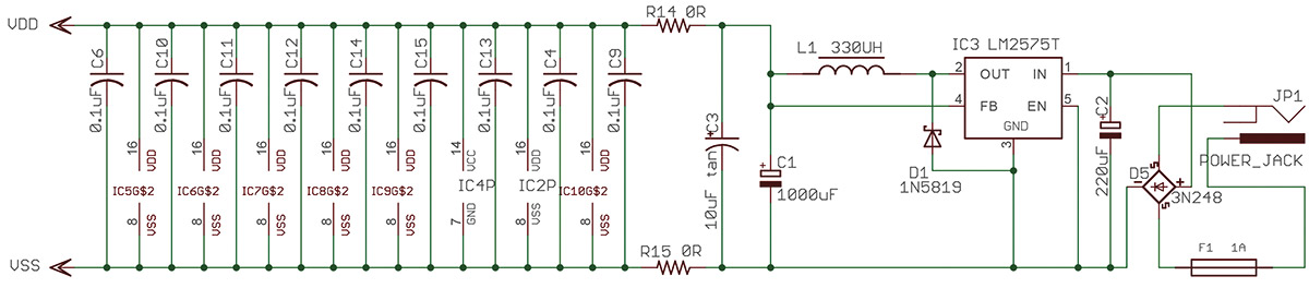
The power supply is fairly simple, using a switch mode buck converter to provide the five volts required for the clock (Figure 7).
FIGURE 7. Schematic of the power supply section of the project.
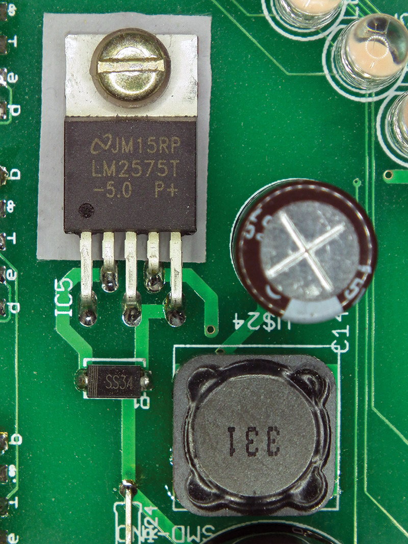
Though I considered a linear regulator, the part became hotter than I was comfortable with while testing in a circuit like this. Additionally, a switch mode supply allows for more choices when it comes to wall wart style power supplies (Figure 8). The greatest current requirement is during the start-up flash cycle, where all six Numitrons are lit for a second at the time; 7x6 segments at about 23 mA = 966 mA total. Maximum current required for the project peaks therefore very close to the one amp limit when all Numitron segments are lit when first plugged in (or after reset).
FIGURE 8. Close-up of the LM2575T regulator installed on the PCB.
The bridge rectifier allows for an AC wall wart to be used, or to allow for different DC wall wart polarity options. You may decide to leave the bridge rectifier out and jump the appropriate points on the board to match your wall wart polarity. Of course, you may also use a different power jack than specified; these are perfect parts to be salvaged from old discarded equipment.
Be sure the wall wart can supply at least 1.5 amps of current at minimum nine volts. The 1,000 µF tank capacitor is a low profile unit so it does not interfere with the front panel. If you use a taller part, you may have to adjust the front panel spacers. The inductor is also an SMD part selected for space reasons. There’s a special mounting tip discussed in a more detailed construction manual that is available at the article link.
The LEDs
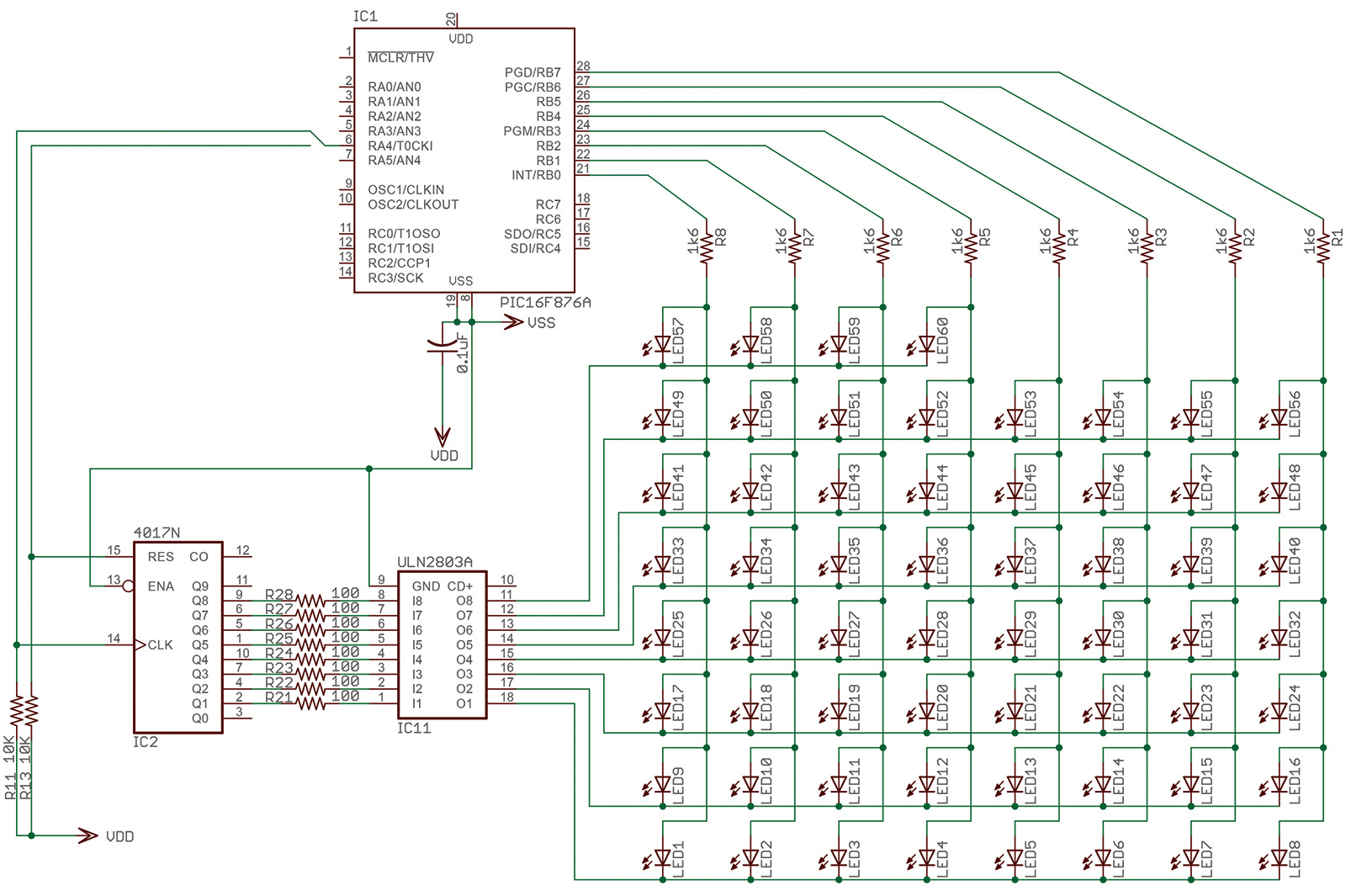
The LEDs are multiplexed in seven rows of eight, with one additional short row of four for a total of 60. The PIC drives one row at a time, and at a couple of mA each, the current draw is well within the specifications for the PIC. By using one byte per row, there are never more than eight LEDs lit at any given time (Figure 9). The circle will appear to be fully lit when required, thanks to a fast multiplex rate and a phenomenon called ‘persistence of vision’ in our eyes.
FIGURE 9. Schematic of the LED driver portion of the project.
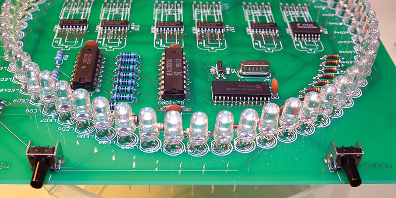
It is important to use high output (also referred to as ultra-bright) LEDs for this design since regular LEDs will appear too dim. You may choose any color you like; the slight difference in voltage requirement for the different colors is insignificant in this project, and does not require any further consideration. Since most of these high output LEDs are “water clear” units, placement is very important to provide a visually pleasing result (Figure 10). The construction manual at the article link provides tips for proper installation and alignment.
FIGURE 10. Close-up of the top of the PCB showing the water-clear LEDs in place.
While a PIC pin will only need to drive a single LED at any given time, the combined current of the full row may need to be sunk in order to light all eight in that row since this exceeds the current output capacity of the CD4017. The ULN2803 acts as the driver there. Also, we need a way to select the correct row synchronized with the data sent from the PIC port. This is the task of the CD4017 decade counter.
It counts the pulses sent from the PIC and activates the appropriate Darlington pair in the ULN2803. After eight pulses, the CD4017 is reset by the PIC, and is ready to start from the beginning. This arrangement allows any individual LED to be addressed by the PIC, respecting all maximum current limits.
The Numitrons
The Numitrons are essentially just little multi-filament incandescent light bulbs from an electrical perspective, and as such, multiplexing them will simply act as a light dimmer. A 1x6 (or even a 2x3) multiplexing arrangement would leave them very dim, so is not a viable option. Luckily — since their current requirement at about 23 mA per segment is fairly low and it is a seven-segment device operating at about five volts — we can drive them with a standard BCD to seven-segment decoder designed for seven-segment LED displays with a max driving output of 25 mA. The CD4511 also has a data latch built in, so it was chosen for this design.
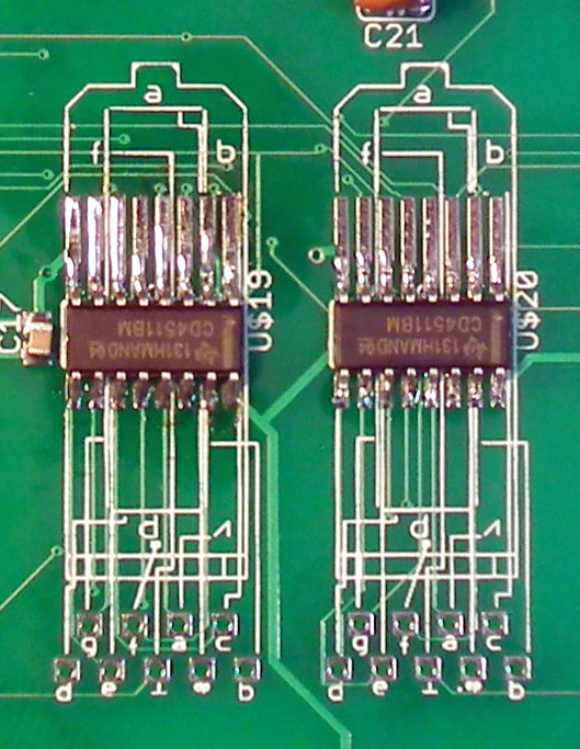
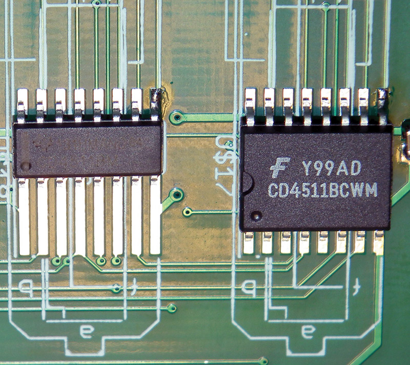
I opted for the SMD version since they neatly tucked behind the Numitron tube, making for a nice clean appearance (Figures 11a and 11b).
FIGURE 11A. Close-up of the surface-mount CD4511 BCD to seven-segment display decoder.
Since I am now rapidly running out of ports on the PIC, I needed an efficient way to control the CD4511s and their latches. This is done by the 74164 shift register in a similar fashion as to how the CD4017 operates in the LED section. The BCD data is presented to all the CD4511s at the same time via the data bus, but decoded and latched only by the CD4511 selected by the SN74HC164 shift register. Synchronization of data and latch selection is controlled in software.
Since the time only changes every second, only one Numitron digit is updated for each time the LED circle is updated. This made the software easier, and it is still much faster than actually required. The CD4511 also has a “lamp test” function which is used to flash all segments during startup and for reset of the clock, also providing an easy way to test the Numitrons.
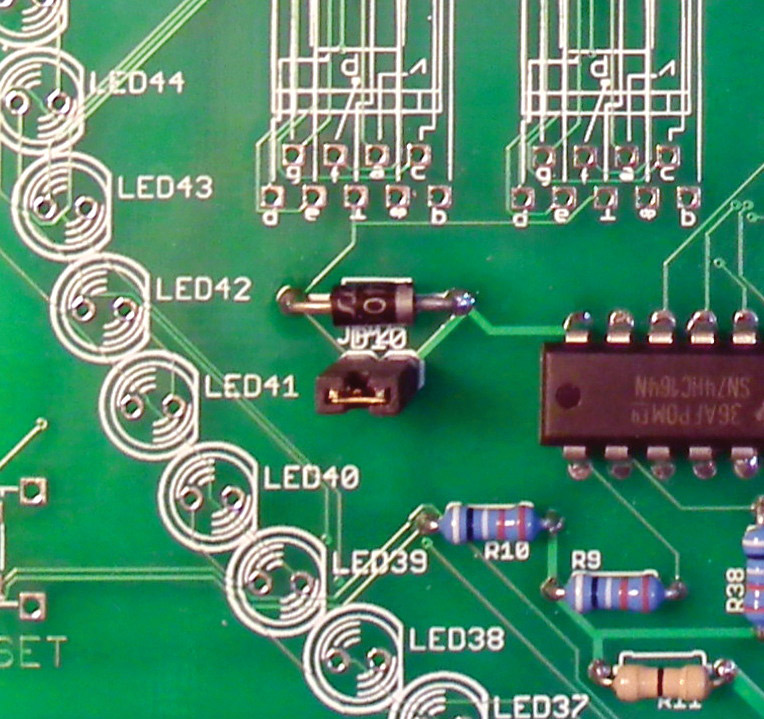
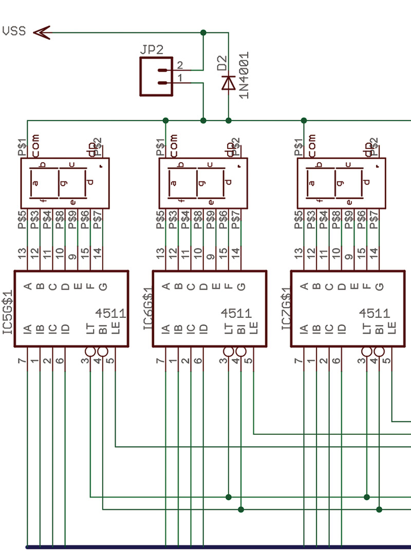
Note also the diode D2 and jumper JP2 (Figure 12a). They were intended to be a rudimentary option for lowering the brightness of the Numitrons and lower the current requirement slightly. It simply relied on the forward voltage drop of the diode, with a jumper to short it (Figure 12b). It is not really required and may be left off the board, in which case a simple jumper wire may be inserted in place of the diode.
FIGURE 12A. Location of the diode and jumper JP2 on the PCB.
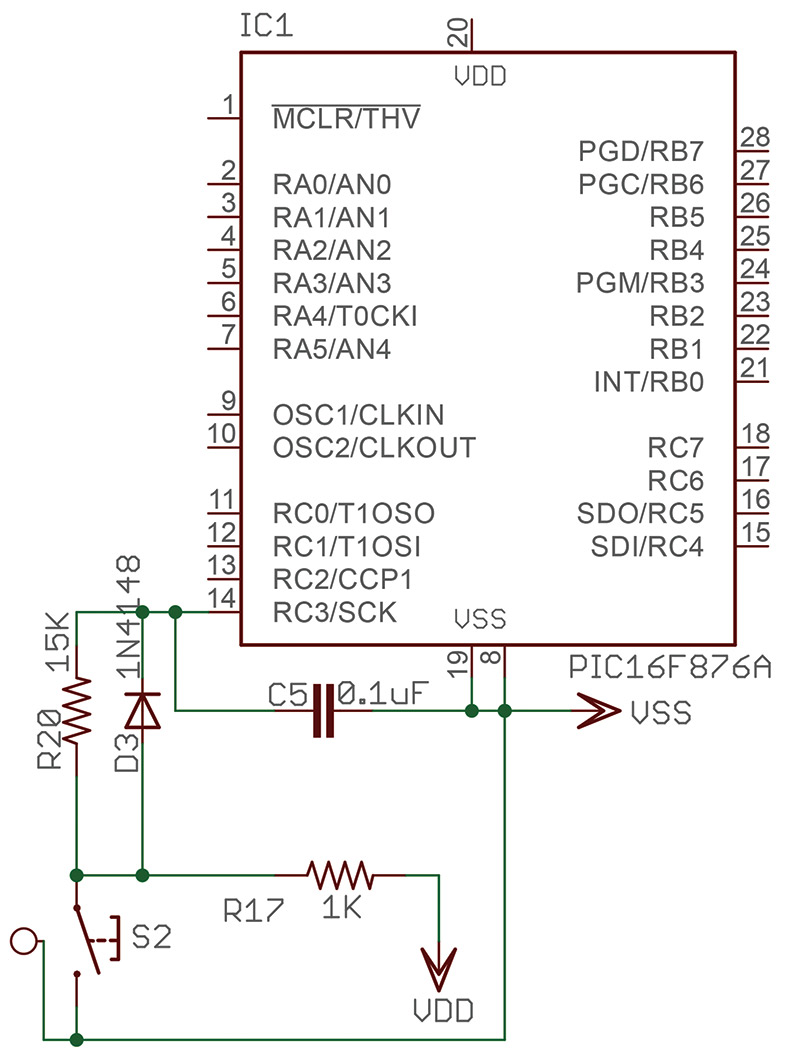
FIGURE 12B. Schematic showing the location of the jumper and voltage dropping diode.
Buttons
The clock is set using only two buttons with multiple functions to control 12/24 hour display selection, LED pattern selection, as well as setting the time. Buttons (or switches) are difficult things to read in high speed digital circuits since the mechanical parts in a switch or button actually bounce like a dropped ball; it takes a bit of time to stop settling in one state or the other when pushed. Debouncing can be done in software, but in this case, a hardware solution was used. The solution is based on the RC time required to charge/discharge a small capacitor (Figure 13).
FIGURE 13. Schematic of the clock set pushbutton debounce circuit.
When the button closes, the capacitor (C7) is discharged through a resistor (R19), allowing the bounce to settle before the voltage on the PIC input pin falls below the logic level 0. When released, the capacitor is charged quickly through R18 and D4. By using this method, no further precautions are required in the software, and the button is treated like an ideal button without bounce.
A fantastic discussion on the subject is listed in Resources.
The Printed Circuit Board
The printed circuit board (PCB) is a standard two-layer version, and has no complicated manufacturing issues for most board houses. As mentioned, the Eagle files as well as Gerber (RS274x) files for those board houses that do not accept native Eagle files are at the article link. Of interest is the somewhat odd looking footprint for the CD4511s (Figure 14).
FIGURE 14. Example of a PCB that can accommodate both wide and narrow versions of the SMD chip.
These chips come in wide and narrow packages, and in the past I have received either or both mixed in my orders. Functionally either one is acceptable, so I created an Eagle footprint that would accept both wide and narrow formats. This is shown in greater detail in the download package for this article.
The circle of LEDs was created by specifying a set of vector coordinates in Eagle by specifying the center, radius, and angle for each LED. The board is about 6” square, and has four mounting holes in which stand-offs are used to hold the front and rear Plexiglas or acrylic panels which allows the finished product to stand vertical.
A free version of Eagle CAD can be downloaded from the link in Resources.
Software
The software is written in MPASM (absolute code) — an assembly language for the PIC. The development IDE (integrated development environment) includes the programming software for the PICkit3 mentioned earlier, and can be downloaded for free from the Microchip website (see Resources).
The source code is available at the article link. The code is heavily commented, so it will help those who wish to dig further into that aspect of the project. Aside from the rather simple section of code that runs the clock, there is a LOT of stuff involved in running the LED displays. This PIC has two eight-bit internal timers and one 16-bit timer, which each generate an interrupt when overflowing. One is used for the time, overflowing every second to advance the clock; the second is used to schedule the display updates; and the third is used for the LEDs.
In the various LED patterns, a “dot” flies around the circle, filling each circle one second at a time. At the 60 second mark, all dots are lit and reset at the new minute. The dot at the start of the minute must make 60 steps to reach the end, and each subsequent dot makes one step less than the previous one. That means the timing of each step changes with each subsequent second.
Timer 2 has a special register (PR2) that allows the timer period to be changed on-the-fly; the timing values required for each step are stored in lookup tables. The positions of the dot are also stored in a lookup table. Setting preferences (12/24 mode and preferred LED pattern) are stored in the PIC’s internal EEPROM, and are therefore not lost on reset or power failure.
General Notes
Building this project is probably at an advanced skill level, mostly due to the number of surface-mount parts. Even if you don’t intend to build this clock, you may enjoy reading the construction manual since it contains many tips and examples that may be of use to you in this or other projects. None of the SMDs used here are ridiculously difficult to solder by hand, but it does require a steady hand, good light, a magnifying glass, and a good soldering iron.
Soldering SMD Components
Small components are best soldered with small tools. That means a very fine soldering tip, fine point tweezers, and very thin solder. The SMD components in this project are not very difficult to solder, however, I'll describe the methods I use.
Caps, resistors, etc., come in many sizes; 0805 (used in this project) and larger can easily be soldered as follows: Start with placing a small drop of solder on ONE pad. With the tweezers, place the part on the pad, heat the drop, and push the part in place (refer to Figure 10b in the text). If the part is not located properly, reheat the one side and correct. Once properly placed, solder the other side.
A similar method is used for the ICs. Place solder on ONE pad, and place the part. If not located correctly, reheat and reposition. Do NOT push to bend the leg even a little bit. The legs will break easily, and the stress will add to future failure chances (Figure 13a). Please see the construction manual at the article link for more in-depth information.
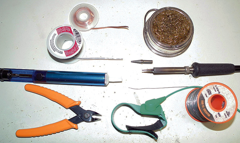
My Weller soldering station has replaceable tips, and the tip I use for the SMD parts is almost needle sharp. Combined with very thin solder (0.020”), it is really not too hard to do (Figure 15). I have included additional tips in the construction manual at the article link. When ordering the SMD capacitors, order a few spares. If you lose an SMD capacitor during construction, look at the end of your soldering iron first. If it’s not there, best go get another one.
FIGURE 15. The tools I use for surface-mount components on PCBs.
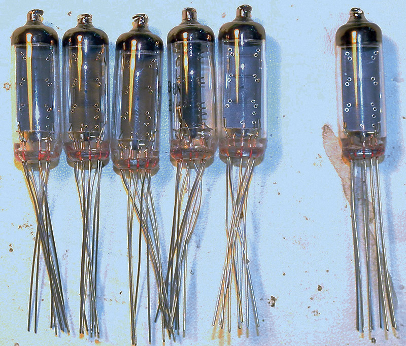
I usually buy things like the small SMD parts in kits from online providers; it provides lots of spares that way. Speaking of online providers, eBay is a good source for inexpensive parts if you are not in a rush. Since you will probably get your Numitrons there (Figure 16), other parts can be ordered at the same time.
FIGURE 16. Typical set of Numitron tubes available on eBay.
LEDs can be found on eBay for very cheap, but it’s definitely “buyer beware” in my experience; many are junk. Don’t buy the “1,000 for a dollar” deal because you will be disappointed. I have included Mouser part numbers for many of the components if you prefer not to take chances. Of course, there are many other excellent vendors to choose from as well (check the advertisers in this issue!).
Another important thing to keep in mind is static protection — especially in the winter when houses become dry, and static discharges (even so small that you can’t feel them) are guaranteed to destroy or damage many of the parts in this project.
Numitron vs. Nixie?
So, now that you’ve had a chance to look over this clock, you might be considering building one ... but maybe you had your heart set on a Nixie tube clock. Though Nixies are very cool and retro in their own right, the Numitron tube clock has the same feel while offering some distinct advantages over Nixies:
They are low voltage devices, so — unlike Nixie tubes — you do not need to insure carefully insulated enclosures to keep users from getting a nasty high voltage “bite.”
They do not suffer from failure states such as “sputtering” where electrode metal collects on the inside of the glass tube dimming or obscuring the display.
They don’t encounter cathode poisoning that requires a potentially distracting anti-cathode poisoning software routine.
In many cases, Numitrons will outlast Nixie tubes as they are typically rated for over 100,000 hours (~11.5 years) of operation compared to some Nixies that are rated for only 5,000 hours (~200 days!).
All in all, Numitrons are a fun and interesting item, and having them used in a clock while surrounded by high tech LEDs makes for a great conversation piece! I highly recommend Numitrons even if you already have a nifty Nixie clock.
If you do end up building a Numitron clock of your own, please let us know! NV