Recap
We continue to build tools to go into our avrtoolbox. Our last episode looked at buffering data. This time, we’ll use those buffers for serial communications while learning about the AVR USART. We will use the software engineering tools we’ve been discussing throughout the avrtoolbox series to design and build a USART library. If you ran the Serial Tester in Workshop 35 and the Ring Buffer Tester in Workshop 36, you’ve already used earlier versions of the USART library and didn’t even know it. AND folks, that is the main reason why libraries are such a powerful software engineering tool — you can use them and not even know it!
Introduction
Much of what we’ve done in these Workshops takes for granted that we have functioning serial communications as a tool for doing our development work — whether we are blinking LEDs or developing a robotic coyote that will leap over our back fence and eat our neighbor’s, yappy little poofy dogettes (okay, that was unkind dream fulfillment on my part). Anyway, somewhere in the background we’ve got a serial link between our AVR embedded system and a Windows PC, easing both development and use of our systems.
Ultimately, for an embedded system to be ‘embedded’ we will cut that link. However, for learning purposes, the serial port is our greatest friend. I personally consider the serial port to be the most powerful embedded systems development tool you can use. The communication channel between a PC and an embedded system can allow you to rapidly upload test programs via an AVR bootloader and you can sprinkle serial statements throughout your code with little messages like “Got to button_reader()” and “Leaving button_reader().” So, if you are running your code with a terminal program you might see “Got to button_reader()” but not “Leaving button_reader().” You‘ll then know that your program crapped out in the button_reader() function between the first and second statements.
I now do virtually all my debugging this way — bracketing suspicious blocks of code with messages until I’ve rooted out the guilty party.
Debugging without the serial port working properly is a bit like doing surgery in the dark. Oh sure, you can spend money and use simulators or emulators, or go really cheap and have the code blink LEDs, but if the design is going to have a serial port built into it anyway, why not use it for development? The only real drawback is that the code to use the serial port has to work properly. So, how do you debug serial code?
Well, I used the serial port to debug itself giving me the classic chicken or egg problem. I can’t tell you the times I’ve sat cussing and looking at a blank terminal trying to get my serial code working properly. I must admit that I had to occasionally resort to blinking an LED to get things going. But the advantage you have is that I’ve got things going for you, so you don’t have to re-plow that field. Let’s learn some more about the USART that makes these serial tools available.
We looked at the PC side of the two-sided serial link way back in Workshops 18, 19, and 20 (these are available at www.nutsvolts.com). In those articles, we learned how to write PC serial code in C# and Visual Basic .NET. We created the Simple Terminal shown in Figure 1 and we even learned how to write a GUI for an Arduino-based voltmeter with a read-out on the PC as shown in Figure 2.
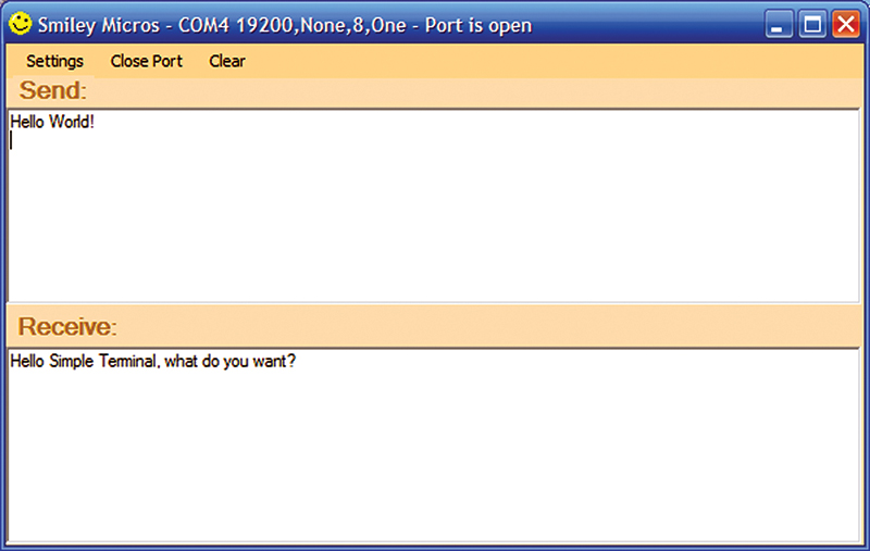
FIGURE 1. A Simple Terminal.
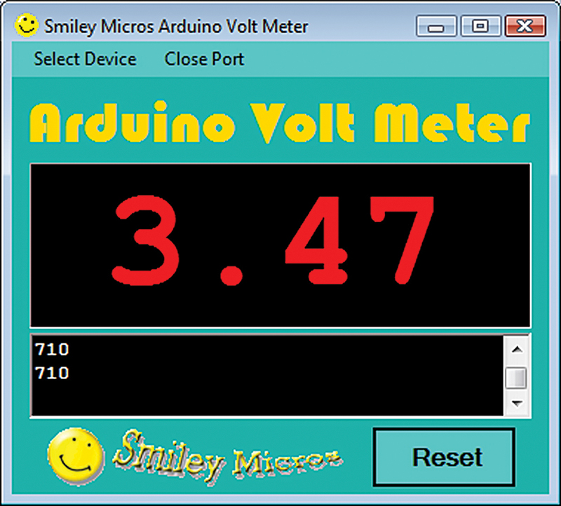
FIGURE 2. An Arduino voltmeter.
The PC at one time had a UART to do serial communications, but that is long gone in favor of USB. So now, we have to use a virtual serial port on the PC side of things. In fact, those three articles were excerpts from my book Virtual Serial Port Cookbook where you can learn how to use the FTDI FT232R to ease your communications between a PC and a microcontroller. (If you find this intriguing and want to help support your favorite technical magazine and writer, you can get the book and an educational parts kit from the Nuts & Volts website.)
A Very Brief History of Serial Communications
There are some seriously oddball things about USARTs and serial ports, mostly due to accidents of the history and the evolution of serial communications, so let’s first take a look at that history and get a feel for the origins of some of the weirdness.
Why do we call the communication speed ‘baud rate?’ Why does a serial connector have a ring indicator pin? Why does a PC keyboard have a ‘Ctrl’ (control) key?
Frankly, a lot of the hardware and software terminology for serial communications seems weird when seen out of the context of how we arrived at today’s serial communication techniques. This next section skims the surface of a large topic primarily to show how some of the terms we will be using came to be.
Samuel F.B. Morse
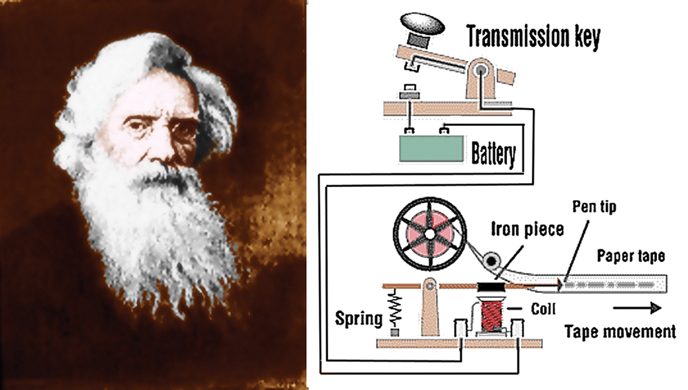
FIGURE 3. Morse self-portrait (yes, he was an artist) and his telegraph machine.
Morse (Figure 3) patented the telegraph in 1840. The name comes from the Greek tele = far away, and graphos = writing. True to its name, the original telegraph machine ‘wrote’ with dots and dashes on paper.
Morse’s real invention was not the transmitter or receiver — which were based on devices that were being played with in electric laboratories of the time. His contribution was a binary code (Figure 4) that allowed characters to be sent as a serial stream of electric signals. He made the most commonly used characters (such as A, E, and T) into the simpler codes and the less commonly used (such as Q, X, and Z) into the more complex code.
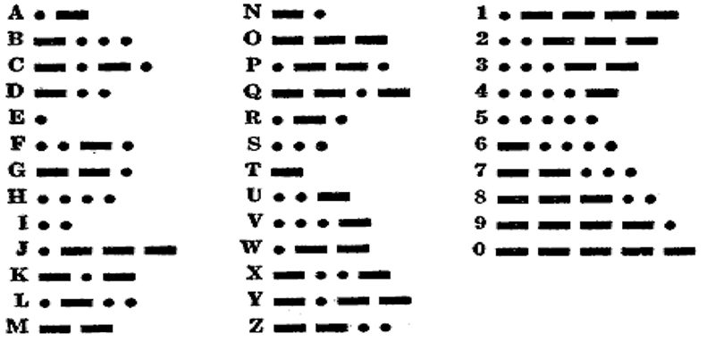
FIGURE 4. Morse’s eponymous code.
Emile Baudot
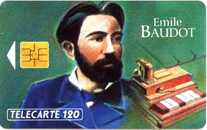
FIGURE 5. Emile Baudot pictured on a French phone card.
In 1874, Emile Baudot (Figure 5) invented a five-bit binary code that used a five-key transmitter. By using mechanical clockworks, the five bits were shifted out onto a single wire and used by the receiving station to print a character on paper. Five bits can uniquely encode 32 characters. Later modifications to Baudot’s code changed the code to 26 character codes and 6 control codes. Two of the control codes were used to select either a 26 letter code or a 26 number/punctuation code table. The remaining four control codes were used for mechanical instructions to control the remote printer. With this new code, an operator could cause the remote printer to print 52 characters and could also control where on the paper the characters were printed.
If you wonder why this matters, look at your computer’s keyboard and note the Ctrl key. It is used to alter the meaning of the rest of the keyboard in much the same way as was done by Baudot’s apparatus, which is a direct ancestor of your keyboard. Also, when we transmit something we will use the ASCII code. We will see that there are a lot of atavistic printer control codes such as CR (Carriage Return), LF (Line Feed), and BEL (for bell, as in dingaling). We might wonder why we need such ‘characters’ in our attempts to send data between a PC and a microcontroller since neither has a carriage, a roller, or a dingalinger. Now you know.
Baud rate refers to the number of unique symbols that can be transmitted per second — the actual physical ability of the system to change states each second. There is often some confusion in the use of Bd (Baud) and bps (bits per second). The bps refers to the amount of information that can be transmitted each second. If each physical state change represents a bit of information, then Bd = bps. While this often is not the case, in our use where one state change represents one bit of data, we will use them interchangeably.
Teletype Machines
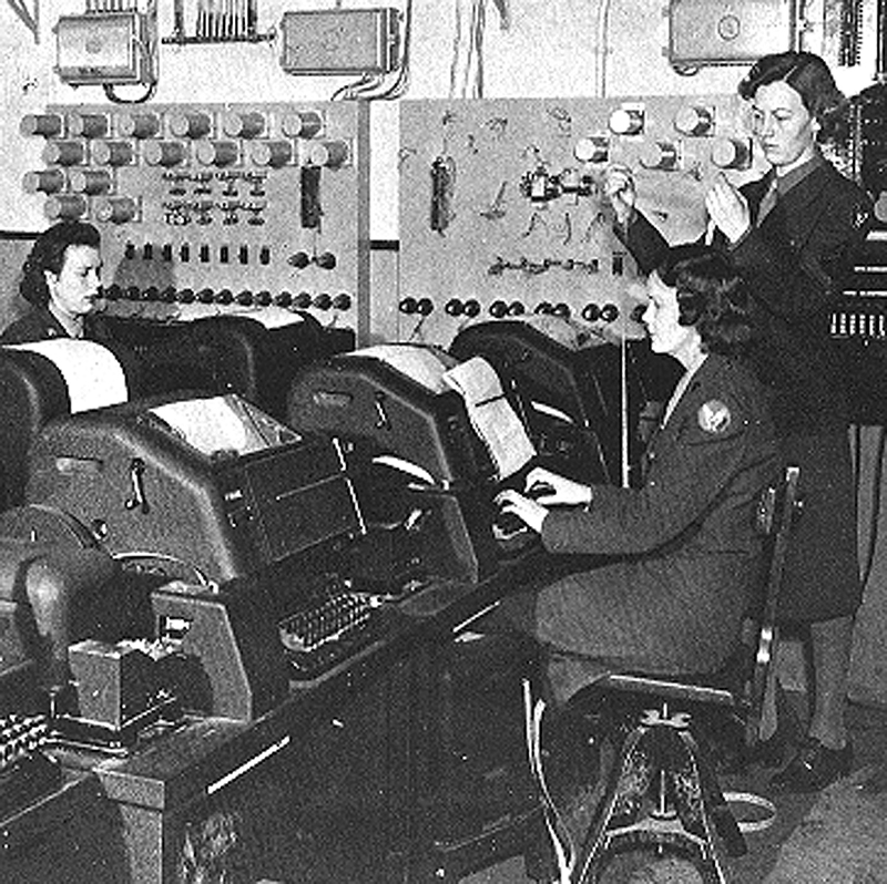
FIGURE 6. WAC teletype operators during World War II.
Baudot’s invention evolved into the teletype machine — an electro-mechanical typewriter that could act as both a transmitter and receiver of text messages over long distances.
In early computers, a teletype machine (Figure 6) was used to enter characters that were punched into cards or paper tape for loading programs into computers. [During WWII, the Colossus computer at Bletchley Park was used to crack encrypted German teletype messages.] Eventually, direct connections were developed to allow the teletype to function much like a PC keyboard.
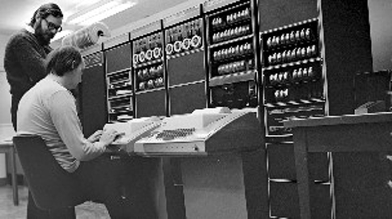
FIGURE 7. C being invented on a more recent teletype machine.
Figure 7 shows Dennis Ritchie (inventor of the C programming language) standing next to Ken Thompson (inventor of Unix), designing the original Unix operating system at Bell Labs on a PDP-11 using a teletype machine to ‘talk’ to the computer.
RS-232 and Modems
The telegraph and teletype machines used a binary (on or off) signal to transmit and receive data. However, the world was wired not for binary signals, but for telephones that sent analog signals (voice — 300 to 3,400 Hz). During the 1950s, folks figured out how to allow binary signals to be sent over these plain old telephone lines by acoustic frequency MOdulating and DEModulating of the signal. Thus, the name modem.
The RS-232 standard was written to allow teletype machines — which were referred to as DTE (Data Terminal Equipment) — to link to a modem — referred to as DCE (Data Communication Equipment) — that could then transmit the binary data from a teletype machine over a phone line to a distant computer. There were several iterations of this standard, but by 1969 RS-232C became the standard that would eventually be adopted (sort of) by Microsoft for the PC serial port. The ‘sort of’ is necessary since the PC isn’t exactly 100% pure, but close enough that the PC serial port often became known as the RS-232 port.
The port has nine pins. Data is transmitted on the TxD pin and received on the RxD pin. Six additional pins are used to control the communications between the PC and the modem. They are the DCD, DSR, DTR, RTS, CTS, and RI, which we’ll learn a lot more about later. The serial port was originally intended to be used with modems, but designers found that it could also be used to communicate with other peripheral devices such as mice, drawing pads, oscilloscopes, etc., thus leading to our more generic use for communicating with microcontrollers.
So now you know that we call the communication speed ‘baud rate’ after Emile Baudot; that a serial connector has a ring indicator pin because the original connector was meant to attach to a modem and use a telephone line which ‘rings’ when a call comes in; that a PC keyboard has a ‘Ctrl’ (control) key because it evolved from Baudot’s original keyboard; and that any other weird term you come across probably has a historic reason for being used. Just as a fun factoid of interest, the Arduino uses the DTR pin of the modem to reset the AVR so that you can use the bootloader to upload applications.
So, what does this have to do with USART?
Early in the development of digital systems, all the above arcania was put into a single IC peripheral that came to be known as a UART: Universal Asynchronous Receiver Transimitter. Like many useful peripheral ICs (memory, ADC, timers, etc.) the UART was soon put on the same silicon as a microprocessor, like the AVR core. The old-fashioned UART only did asynchronous (not occurring at predetermined or regular intervals – no clock) communication, but Atmel added some features that let theirs do some synchronous (does occur at predetermined regular intervals – clocked) things. They also added an S to the name that has confused folks mightily. We won’t be using the S other than in the name. So, just get used to the fact that when we say USART we are actually dealing with the venerable UART. However, since this is an Atmel peripheral, we’ll use their name for it (grudgingly). Clear? I didn’t think so.
AVR USART Hardware
I suggest that you get the Atmel ATmega328 datasheet and take a look at the section on the USART. Yup, this beast is like most peripherals. It can do so many different things that the real hard part is figuring out the limited subset of things that you want it to do. We won’t be using 90% of what you see in the datasheet, but the trick — as usual — is figuring out which 10% we want to use. There are things that it can do that I have never seen done in any system I’ve used — like allowing five, six, seven, eight, or nine data bits. I’ve only ever used eight bits and have only seen seven and nine on other systems (never five or six). Guess somebody somewhere in some historical context used these so they are there if you need them.
To simplify things, let’s keep this as simple as possible by using only the most common modem parameters: eight data bits, no parity, one stop bit, and no handshaking. Yes, so the datasheet is hard. So let’s try to simplify it a bit.
Set Up the USART
Using Aliases for Comprehension and Portability
We have already discussed a bit about using aliases for register and bit acronyms in earlier Workshops, but let’s risk some repetition and revisit the concepts (anyway, repetition is supposed to help learning). We have two main problems with registers and the bits in them. First, there are hundreds of them, and second, they are named using acronyms making for a double whammy of “wazzat!?” when you look at their names. Quick — what is UCSR0C or UPM01?
You are likely to see both of these in some AVR source code, so you might expect that you are supposed to know what they mean. The UCSR0C is the USART Control and Status Register C for USART0, and the UPM01 is USART parity mode bit 1 for USART0. Now don’t you feel like a real dummy for not knowing that? Well, I don’t and personally I think folks who use the raw acronyms in their code are foolish. Wouldn’t it be better if they had used an alias in the first place that spelled it out? For example say they used:
#define USART_CONTROL_STATUS_REG_C        UCSR0C<br />
#define USART_PARITY_MODE_BIT_1        UPM01
Then, when they look at their code and see USART_CONTROL_STATUS_REG_C or USART_PARITY_MODE_BIT_1 they will have a much better chance of knowing what is going on without having to dig out the datasheet to find the acronyms. The compiler doesn’t care because it doesn’t see the long name anyway since the preprocessor substitutes the acronym. Of course, you do have the bother of all the extra typing and I do hate typing the ‘_’ character, but I’ve found in the long run doing things this way is just adding more documentation for your code. But that is generally a good thing — especially for educational code — so that’s what we will do.
Another example of why this is useful is that not all the AVRs use the same acronyms for the same register, and some have more than one USART. Using defines helps ease reusing code for multiple devices as shown here:
// Remove comment from only one device<br />
//#define USART_ATMEGA169<br />
#define USART0_ATMEGA328<br />
//#define USART1_ATMEGA328<br />
     …more devices…
#if defined(USART_ATMEGA169)<br />
   #define USART_CONTROL_STATUS_REG_C    UCSRC<br />
   #define USART_PARITY_MODE_BIT_1        UPM1<br />
     …more aliases…<br />
#elif defined(USART0_ATMEGA328)<br />
   #define USART_CONTROL_STATUS_REG_C    UCSR0C<br />
   #define USART_PARITY_MODE_BIT_1        UPM01<br />
     …more aliases…<br />
#elif defined(USART1_ATMEGA328)<br />
   #define USART_CONTROL_STATUS_REG_C    UCSR1C<br />
   #define USART_PARITY_MODE_BIT_1        UPM11<br />
     …more aliases…
This allows you to use the same source code for each device, only changing one line to select the device. So, the code can have USART_CONTROL_STATUS_REG_C and the preprocessor gets to decide if that is UCSR0C or UCSR1C, depending on the #define you selected. Do this and give your library an indicative name like libavr_USART0_atmega328.a and away you go.
You’ll find something like this in the avrtoolbox USART directory where we have libraries for the AVR Butterfly (ATmega169), the Arduino board (ATmega328), and the BeAVR (ATmega644).
Which Registers and Bits?
While I promised that we would only use a small subset of what the USART can do, we still have to set a bunch of registers and bits. To further simplify our life, let’s just look at what we have aliased for the ATmega169 (AVR Butterfly) in USART.h:
// Registers<br />
#define UART_BAUD_RATE_HIGH        UBRRH<br />
#define UART_BAUD_RATE_LOW        UBRRL<br />
#define UART_CONTROL_STATUS_REG_A    UCSRA<br />
#define UART_CONTROL_STATUS_REG_B    UCSRB<br />
#define UART_CONTROL_STATUS_REG_C    UCSRC
// Bits<br />
#define UART_ENABLE_TRANSMITTER    TXEN<br />
#define UART_ENABLE_RECEIVER        RXEN<br />
#define UART_READY_TO_TRANSMIT    UDRE<br />
#define UART_TRANSMIT_COMPLETE    TXC<br />
#define UART_RECEIVE_COMPLETE    RXC<br />
#define UART_DATA_REG            UDR<br />
#define UART_STOP_BIT_SELECT        USBS<br />
#define UART_CHARACTER_SIZE_0    UCSZ0<br />
#define UART_CHARACTER_SIZE_1    UCSZ1<br />
#define UART_CHARACTER_SIZE_2    UCSZ2<br />
#define UART_MODE_SELECT        UMSEL<br />
#define UART_DOUBLE_SPEED        U2X<br />
#define UART_FRAME_ERROR        FE<br />
#define UART_DATA_OVER_RUN        DOR<br />
#define UART_PARITY_ERROR        UPE<br />
#define UART_PARITY_MODE_0        UPM0<br />
#define UART_PARITY_MODE_1        UPM1<br />
#define UART_MULTI_PROCESSOR_<br />
COMMUNICATION_MODE            MPCM<br />
#define UART_TX_COMPLETE_INTERRUPT_ENABLE    TXCIE<br />
#define UART_RX_COMPLETE_INTERRUPT_ENABLE     RXCIE<br />
   #define UART_DATA_REGISTER_EMPTY_INTERRUPT_ENABLE    UDRIE<br />
#define UART_RX_DATA_BIT_8            RXB8<br />
#define UART_TX_DATA_BIT_8            TXB8
That is five registers and 23 bits! The long form of the names are somewhat explanatory, but you may want to look at the datasheet to get the details if you are excessively curious or masochistic. You can see why we want to set this up one time, get it working, put it in a black box with lots of duct tape, and never look at it again.
How Do We Set These Registers and Bits?
We have two USART initialization functions: one initializes everything and the other relies on defaults for all but the baud rate. The comprehensive function has a list of parameters that it sets:
void USART0_init(uint32_t baud,\<br />
 uint32_t freq_cpu,\<br />
 USART_mode_t mode,\<br />
 USART_databits_t databits,\<br />
 USART_stopbits_t stopbits,\<br />
 USART_parity_t parity)
In the function, we call various other functions or macros to set the parameters, such as:
USART0_mode(mode);
which is a macro:
#define USART0_mode(x) bit_write(x, UART_CONTROL_STATUS_REG_C, BIT(UART_MODE_SELECT))
Next time, we are going to take a look at the C standard library and apply what we’ve learned about ring buffers and USART libraries to get the venerable C printf() function working, along with some string manipulation functions and a command-line interpreter that will soon become one of your favorite development tools. NV