As an avid hobbyist, I would like to have a convenient way to recharge my battery powered projects without having to tie up the USB ports on my computer. Borrowing from the concept of the wireless chargers on the market, I decided to build my own. So if you like the idea of having a wireless replacement for your USB port, open up your surplus parts drawer and let's start the induction process.
How Does Inductive Coupling Work?
Wikipedia defines Resonant Inductive Coupling as “the near field wireless transmission of energy between two coils that are tuned to resonate at the same frequency.”
The formula for calculating the resonant frequency is:
ƒr = 1/(2*pi*√(LC))
You can use a meter to determine inductance, but not for the distributed capacitance that accumulates between windings. You can use the following formula to determine the self-capacitance or the interwinding capacitance:
C = .29L + 0.41R + 1.94[ √ (R^3/L) ]
Where
C = Self capacitance in picofarads
R = Radius of coil in inches
L = Length of coil in inches
The prototype coil for this project was wound using some surplus wire I had left over from a previous project. The size of the coil was based on a dimension that was indicative of most of my average size projects. The coil was a flat, single layer spiral coil created with 26 AWG enameled magnet wire that had a 1” inner diameter and an outer diameter of 2.5”.
The coil was wound with 44 turns and had an inductance of 152 uH with a parasitic capacitance of 1 µF. Using the resonant frequency formula just given, I discovered that the coil would resonate at 12.9 kHz. If you want to use your own coil design, you will need to find the resonant frequency for it.
There are online sites that serve as calculators that can make the job a lot easier; there is one such calculator located at www.1728.org/resfreq.htm that can solve for frequency, capacitance, or inductance as long as you have two of the three variables. You may want to start with the coils used in this project before you try using coils of your own design.
A wireless charging system needs to contain the following circuit elements:
- Any type of oscillator capable of producing the resonant frequency.
- A power transistor to serve as an amplifier for driving the primary coil.
- A set of coils that serve as a primary transmitter and secondary for the receiver.
- A full wave rectifier to convert the incoming AC to a DC value.
- A voltage regulator to create a useable voltage for charging depleted batteries.
- A circuit to manage the charging process for Li-Ion or NiMH battery chemistries.
The schematic shown in Figure 1 is an example system with test points for troubleshooting possible problems, plus the meter placement that is necessary to calculate power efficiency.

FIGURE 1. Inductive charger schematic with test points.
Building The Circuit
Before you can fully test the operation of the transmitter and receiver circuits, you will need to construct a set of coils.
Creating The Coils
If you are going to design your own coils, try experimenting with varying diameters of wire, coil geometries, and different coil sizes. The following is a description of a coil design technique that is the culmination and the distillation of many moons of effort in the application of a single method.
The coil construction can be the most difficult part of this project. The suggested coils for this project are a flat pancake style that is reminiscent of the old Tesla primary coil design. They can be almost impossible to fabricate without a specific technique. I have tried numerous ways to create these coils; the method I discuss here provides the most consistent results.
You will need two acrylic blocks per coil. The blocks should be of a thickness that makes it difficult to deform them. I find that about 1/4” thick acrylic is fairly rigid under stress. You can find prefab blocks at most well stocked craft stores; they are typically used for making stamping tools. I found the ones I used at Michaels craft supply, but they can be ordered from various places online.
The only problem with prefab blocks is the lack of variety of dimension. The blocks I used are 2.5” square which works fine given the dimension of the circuits that I would like to make wirelessly rechargeable. For the transmitter and receiver coil, you will need two sets of block configurations illustrated in Figure 2.
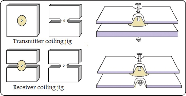
FIGURE 2. Winding jigs for transmitter and receiver coils.
Cut a 1” diameter disc from any mylar material. The disc thickness needs to be the same thickness as your wire. I had some 26 AWG enameled magnet wire from a previous project, but any gauge wire (within reason) will work. Drill a 3/16” hole in the center of the two acrylic blocks and in the center of the 1” mylar disc. To make the “U” shaped cut-outs, drill a 1/4” hole that straddles a portion of the 1” disc as shown. With a dremel cutting wheel or hacksaw, cut the block from the edges to the 1/4” hole so that it matches the shape in Figure 2.
Using a machine screw, make sure the pieces can be assembled (refer again to Figure 2). Insert one end of the wire as shown leaving about 6”, and wind the coil as illustrated in Figure 3; keep a slight tension on the wire as you wind.
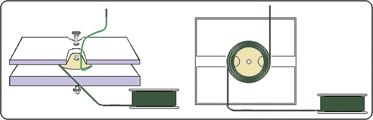
FIGURE 3. Winding the transmitter coil.
Wind the coil until it just reaches the edge of the block. Cut the wire leaving six inches on this end, as well. Tape the end of the wire to one of the blocks to keep the coil from unraveling. With a small brush or toothpick, apply Vaseline to the intersection of the cut-outs in the plastic block to the coil as shown in Figure 4.
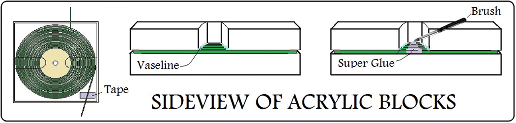
FIGURE 4. Applying glue to freeze finished coil design.
Apply Super glue between the edges of the U shaped cut-outs with the glue applicator brush, also shown in Figure 4. The Vaseline will prevent the glue from attaching to the edges of the plastic block cut-outs.
Once the glue dries, disassemble the jig and you are left with the coil glued to the block. This will serve as the transmitter coil in the charging base.
The receiver coil is fabricated much the same way except that you will use cut-out acrylic blocks on the top and bottom as shown in Figure 5. Vaseline all four intersections of the coil to the acrylic block and glue the coil the same way as the transmitter coil. Once dried, disassemble the jig as shown in Figure 5 and you will be left with just a flat pancake coil. Leave the disc in the center of the coil.
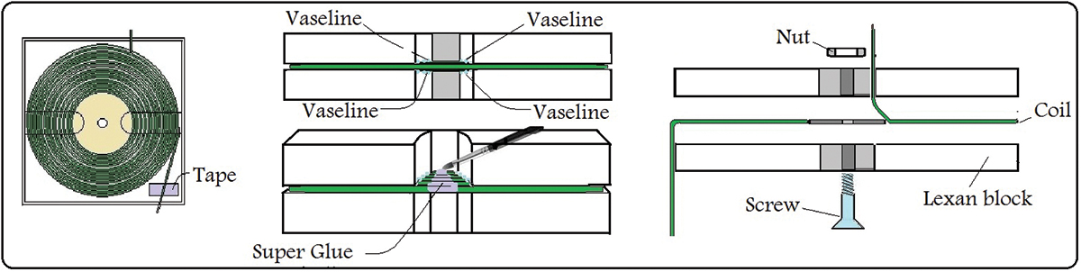
FIGURE 5. Method for creating receiver coil.
You might want to glue more of the coil area after separating it to make it more stable. This coil will mount onto the receiver board, along with the rectifying parts and voltage regulating electronics.
When finished, you should end up with a transmitter coil glued onto the top of one of your acrylic blocks (refer to Figure 6). The receiver coil should not be attached to either of the acrylic blocks, and the 1” diameter mylar disc should remain in the center of the coil for easy mounting to the receiver card. Both coils should measure approximately one ohm of resistance.
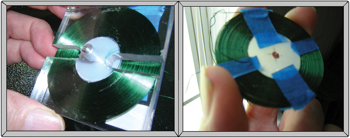
FIGURE 6. Freshly wound transmitter and receiver coils.
Once you have finished with the coils, we will begin by breaking the schematic (Figure 1) into the construction of individual transmitter and receiver circuits. I do recommend building both circuits on separate breadboards before committing your design to a final circuit board.
Building The Transmitter Circuit
The transmitter requires a 12V power source capable of delivering one amp. The PICAXE operates from 2.4V to 5V, and will require a voltage regulator to produce a voltage in this range. Use either a 3.3V or 5V regulator such as the LM2950 or LM7805. The PICAXE 08M2 microcontroller serves as the oscillator that generates the resonant frequency. The output of the 08M2 is fed to the gate of a MOSFET power transistor that drives a coil directly from its drain. A snubber capacitor from the drain side of the MOSFET to ground is included to prevent damaging the MOSFET from inductive kickback during turn-off transitions. The back-EMF can be quite considerable (10x the input voltage), even with air core transformers.
The best capacitor to have here is an MKP grade that is often used when generating high current pulses, but a higher voltage metalized film capacitor (MPF) will suffice. An ammeter should be placed as shown in the schematic to measure the input current consumed by the circuit in order to calculate efficiency.
The PICAXE will need to be programmed to generate the resonant frequency. To do this, add two resistors to your breadboard as shown back in Figure 1. Connect your programming cable to the audio jack and load the following lines of code to generate a 12 kHz output with a 50% duty cycle:
BASIC CODE TO GENERATE 12 kHz
setfreq m8             ‘REM sets the operating speed to 8 MHz<br />
do                     ‘REM beginning of loop<br />
pauseus 1200           ‘REM creates a 1200 µS pause<br />
pwmout c.2, 153, 308   ‘REM generates a 12 kHz output<br />
                       ‘@ 50% duty cycle<br />
pauseus 1200           ‘REM creates a 1200 µS pause<br />
loop                   ‘REM End of loop
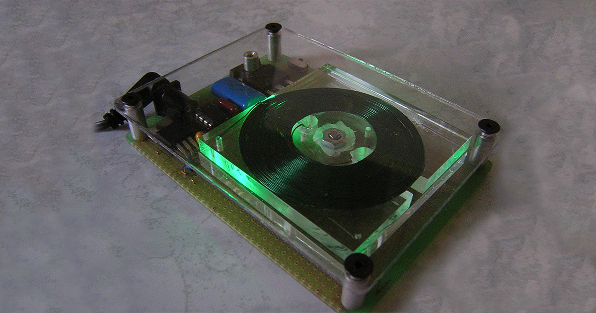
The code to produce any frequency with a set duty cycle can be generated by using the pwmout wizard of the compiler and is invoked from the program menu. In the prototype circuit, I placed the “PWR ON” LED in the side of the 1/4” acrylic coil platform. It creates an interesting effect when the circuit is turned on.
Building The Receiver Circuit
Once energy has been coupled to the secondary, a rectifier converts the incoming AC to a DC value. The output may not follow the normal turn ratio and be higher than the input voltage. This is due to ringing on the outgoing wave that gets attenuated on the secondary, causing a rise in voltage. This is not a problem unless it exceeds the 35V input limit of most regulators.
A snubber capacitor of 0.1 µF should be placed between the outputs of the secondary coil to block inductive kickback. Feel free to use either discrete diodes or a packaged bridge rectifier in the design. Be sure that the devices you implement can withstand one amp of current at 50V. The DC output is regulated to 5V using an LDO regulator such as an LM78L05. It is very important to use the LDO version regulator to provide a source of constant current and constant voltage, much like USB output.
To measure the output power of the receiving circuit, place a resistive short across the regulated 5V output that can be switched in using a SPST slide switch as shown in Figure 1. Use a meter to read the voltage drop across the resistor. Using Ohm’s Law, you can compute the power output by I = E / R. Use a resistance value with a base of 10 to make calculations easier. Be sure to use an adequate wattage resistor for the dummy load. By generating current values close to one amp, you will need a resistor rated at 5W.
Testing Your Circuit
When breadboarding certain power transistors, it may be necessary to attach smaller diameter wires to the leads in order to plug into your breadboard. You will also need a way to intercept the (+) lead from your power supply to attach the ammeter.
Connect the coils to your breadboard circuits and attach the meters as shown back in Figure 1. Place the receiver coil over the transmitter coil, separating them with one of the acrylic blocks to act as an insulator. Apply power to the transmitter circuit and record the values from both meters. Close SW1 to short the dummy load across the output of the regulator.
You should notice the input current value rise due to the short being reflected back to the primary. You may need to heatsink your power transistor. If it becomes excessively hot at resonance, you need to check your work. Try the suggestions given in the Troubleshooting section first.
CHARACTERIZING POWER OUTPUT & EFFICIENCY
FDH055N15A — N-Channel Power Trench MOSFET 150V, 167A, 5.9 mW
COIL DIAMETER = 2.5 | APERATURE = 1” | SEPARATION = 0.25”
FREQUENCY = 12.9 kHz DUTY CYCLE = 50%
Input Voltage = 12V Output Voltage 5.06V (31V unregulated)
Voltage Drop across 10 ohm load shorted = 0.710V ( I = E / R ) 710 mA
Input = 900 mA Output = 710 mA Efficiency = 710 mA / 900 mA * 100 = 78%
It’s very simple to add a recharging receiver to your projects. The following is an example of a battery powered project that I converted to be wirelessly rechargeable. I took an existing project that is an 8 x 8 LED matrix Pong game that is powered by a lithium-polymer battery source. The game has a footprint of 3” x 2” with a battery supply on the back of the board. I mounted the receiver coil on a board with the same dimension as the game, leaving plenty of room for the electronics in the receiver.
I wanted to keep the receiver card as thin as possible to not add much more depth to the existing project. Figure 7 is a photo of the charging receiver attached to this project design that I want to charge wirelessly.
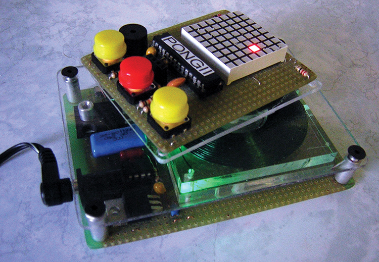
FIGURE 7. Charging a device on transmitter base.
The entire receiver board adds only an additional 1/4” to the depth of the project. A single IC battery charging manager shown in Figure 8 is connected to the output of the 5V regulator. This chip (manufactured by Maxim Integrated) requires just a few external components, and will manage the charging for a single cell lithium battery. The MAX1811 has an LED that indicates when charging is complete.
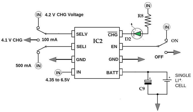
FIGURE 8. MAX1811 li-ion battery charging manager.
I have been able to get a nominal service life of approximately 400 charges with this device. I even use it to charge my super capacitors.
Troubleshooting
This circuit was intentionally designed to be simple, so troubleshooting should be correspondingly easy. The following are voltages that should be present at the various test points shown in the schematic from Figure 1.
- There should be 5V at TEST POINT B (check the 12V supply voltage if not 5V).
- There should be approximately 2.5V at TEST POINT A (check the 08M2 power supply or the code).
- There should be a minimum of 6V at TEST POINT C (check the rectifier or AC across the coil). Test the regulator by connecting the 12V supply to the input terminal.
- You should have 5V at TEST POINT D (check the regulator connections).
- There should be 12V AC or greater at TEST POINT E (check the coil connection if the test points in listings 1 and 2 are okay).
- You should have an AC value at TEST POINT F (check the secondary coil connection if the test point in listing 5 is okay).
Possible Enhancements
You will want to come up with a way to sense that an object has been placed on the charging base to keep the transmitter from running all the time. The most graceful way to do this would be to design a current-sensing circuit that trips when a load is introduced.
I currently take advantage of built-in IR commands with the 08M2, and use an IR circuit as a proximity detection system.
By using a 08M2 in the receiver, a two-way communication may be desirable between the transmitter and receiver. You may also want to make a large charging surface area.
A simple way to accomplish this would be to arrange transmitter coils wired in parallel. If you make printed circuit boards, you may want to create an etched coil for the receiver that can be scaled to fit the application.
By utilizing surface-mount components, the receiver may take on a near credit card size footprint.
Conclusion
Whether you build this project just to study induction or actually apply it to some recharging end, it is guaranteed to be challenging for both novice builders and experienced ones alike. NV
Parts List
| ITEM |
QTY |
DESCRIPTION |
SOURCE/PART# |
| All surface-mounts are 805. All part numbers are Digi-Key unless otherwise noted. |
| Q2 |
1 |
FDH055N15A N-Ch FET (any) |
FDH055N15A-ND |
| J1 |
1 |
1/8" Audio Jack (any) |
2168131 |
| R1 |
1 |
22K ohm 1/4W Resistor |
CF14JT22K0CT-ND |
| R2 |
1 |
10K ohm 1/4W Resistor |
S10KQCT-ND |
| R3 |
1 |
220 ohm 1/4W Resistor |
CF14JT220RCT-ND |
| R4 |
1 |
330 ohm 1/4W Resistor |
A105936CT-ND |
| RDL |
1 |
10 ohm 5W |
ALSR5J-10-ND |
| C1 |
1 |
0.1 µF MPF Snubber Capacitor |
EF2105-ND |
| C3, C6 |
2 |
0.1 µF Bypass Capacitor |
1493-3401-ND |
| C2, 5, 7, 8 |
3 |
10 µF Electrolytic 50V |
P997-ND |
| C4 |
1 |
0.1 µF Mylar Snubber Capacitor |
495-2435-ND |
| D1 |
1 |
3 mm Green LED |
751-1101-ND |
| BR1 |
1 |
Bridge Rectifier |
DF005M-E3/45GI-ND |
| VR1, 2 |
2 |
LM78L05 or LM2940-N Regulator |
LM2940T-5.0-ND |
| SW1 |
1 |
SPST Slide Switch |
CKN9924-ND |
| L1, L2 |
1 |
Asst Magnet Wire |
RadioShack # 278-1345 |
| IC1 |
1 |
08M2 PICAXE Micro |
SparkFun COM-10803 |
| Optional Parts |
| IC2 |
1 |
Batt Manager (see text) |
MAX1811ESA+-ND |
| D2 |
1 |
3 mm Green LED |
751-1101-ND |
| R8 |
1 |
220 ohm 1/4W Resistor |
CF14JT220RCT-ND |
| PCB |
1 |
4.3 x 6.8" Gen Prototyping Board |
Jameco # 206587 |
|
MISCELLANEOUS HARDWARE
Four 2.5" x 2.5" x 1/4" acrylic blocks from a craft supply store.
Threaded standoffs for building a transmitter base (RadioShack).
Super glue with brush applicator.
1/8" Lexan
Vaseline
MISCELLANEOUS TEST EQUIPMENT
VOM with 10A scale feature
Oscilloscope (optional)
|