In the first part, we saw that there are three main components to an analog power supply: input power conversion and conditioning; rectification and filtering; and regulation. We examined the first two components and in this article we will examine the regulation aspect. We will concentrate on the basic three-terminal regulators that are cheap and easy to obtain.
However, it should be remembered that many of the basic design aspects of three-terminal regulators apply to any analog regulator design. In this article, a zero to 30 VDC, zero to one amp, current limited power supply will be developed. The basic cost for parts is around $25.
Basic Three-Terminal Regulator
Figure 1 shows a conceptual design of a three-terminal regulator. (We'll limit our discussion to positive regulators because the negative regulators are virtually the same, other than polarity.) It's important to appreciate how this works in order to properly understand and apply analog regulator concepts.
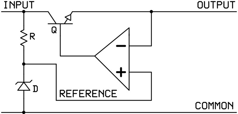
FIGURE 1. The basic approach to the three-terminal regulator is a simple negative feedback op-amp circuit. Although in practice, it’s a bit more complicated than this.
Fundamentally, the regulator is a negative-feedback servo system. The resistor and zener diode provide a stable voltage reference to the non-inverting input of an op-amp. The inverting input of the op-amp measures the output. If the output is higher than the reference, the op-amp slews towards a lower voltage.
Conversely, if the output is lower than the reference, the inversion of the op-amp’s input drives the base of the transistor harder to allow a higher voltage to pass. This design concept is pretty straightforward (although implementing it can be fairly complex).
There are a number of points about this basic design that need discussion. The first is that the pass transistor is acting as a variable resistor. It reduces the input voltage by limiting the current. As you can imagine, a fixed resistor in this situation must be able to dissipate plenty of heat, so it’s the same for the transistor. We'll examine this in more detail later.
The second point is that there's a voltage drop across the pass transistor. All bipolar semiconductor junctions display this effect. This means that the input voltage must be higher than the output voltage for proper operation. For the standard three-terminal voltage regulators, this voltage is about 1-2.5V, depending on temperature and current drawn. (However, for proper design purposes, the 2.5V “drop-out” voltage should always be employed.)
If the desired input-output voltage difference is less than this 2.5V, the circuit will no longer have the headroom to regulate properly and drop out of regulation. (There are other “low-dropout” or LDO regulators available that can operate with much less input-output differential — some as low as 0.1V. However, care must be taken to provide proper capacitive loading or else they may not function properly.)
The third point is that it takes some small amount of time for an output change to propagate through the op-amp and transistor (loop delay). During this time, the output is not being properly regulated. Obviously, the faster the op-amp and transistor, the shorter this transient will be. However, manufacturing fast high-power transistors is not easy or cheap.
Additionally, the faster the transistor and op-amp circuit is, the more prone to oscillation it is. Having your power supply oscillate is not a good thing. Most three-terminal regulators have a transient response (closed-loop delay time) of about 30 µs.
The last point concerns adjustable voltage regulators (Figure 1 shows a fixed-voltage regulator). Without getting into a long technical discussion, it's difficult to provide a stable and cheap reference voltage below 1.2V. This limits the minimum output voltage of adjustable regulators. However, we’ll see a cheap and easy solution to this problem, later.
Additional Components Needed
For the fixed voltage regulator, only an input and output bypass capacitor (connected to ground) are required (typically 0.1 to 1.0 µF). These are to stabilize the op-amp in the regulator. If the large filter capacitor is in close physical proximity (less than 6”) to the regulator input, then the input bypass capacitor can be omitted.
In theory, the output capacitor can also be omitted. However, if your circuit to be powered just happens to have a load capacitance of 500 pF to 5,000 pF, then the regulator might oscillate.
Using a 1.0 µF output bypass capacitor forces the op-amp into a stable operating mode. It's always a good idea to spend a few pennies on this to be sure you have a reliable power supply.
Figure 2 shows the proper design for an adjustable regulator. The input and output bypass capacitors (Ci and Co) are the same as in the fixed regulator implementation.
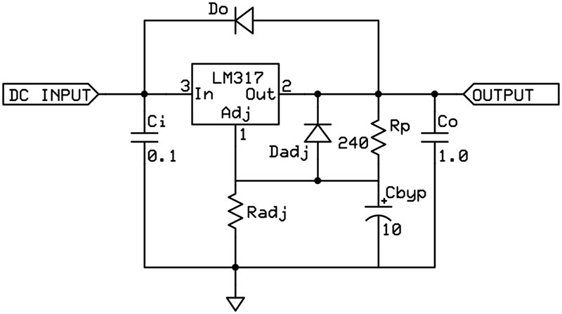
FIGURE 2. The practical implementation of the LM317 adjustable regulator requires a few additional components for optimal performance and reliability. The text describes the additional parts and their function.
The two resistors (Rb and Radj) are required to choose the output voltage. Typically, Rp is set at 240 ohms to provide a proper current (typically about 50 µA) into the feedback of the op-amp.
Radj is used to vary the output to the desired value. The capacitor connected to the adjustment pin (Cbyp) is used to improve ripple/noise rejection. This is especially useful if the raw DC input is coming from a switching power supply which is typically quite noisy.
The diodes are used to protect the regulator against unexpected voltage reversals. If the input should be shorted to ground, capacitors on the output and/or the adjustment pin will still maintain their voltage. They will then discharge backwards through the respective pins towards the input. This can destroy the device.
If there is no adjustment bypass capacitor used (Cbyp), then the Dadj can be omitted. If you're sure that the device being powered will never have 10 µF or more load capacitance, then Do can be omitted, as well.
Adjustment Calculations
It's important to remember that (for adjustable regulators) the adjustment pin acts as a non-inverting feedback point to the internal op-amp. As such, the op-amp will do whatever it can to maintain the voltage on this pin (which is specified to be 1.25 volts below the output). So, if we apply a voltage (through a resistor) to this pin, the output will go up. If we short this pin to ground, then the output will fall to about 1.25 volts. If a negative 1.25 volts is applied, then the output will go all the way to zero volts.
Generally, a voltage divider is used to pass some of the output voltage back into the regulator to set the output voltage (as shown in Figure 2). The equation is Vout = Vref (1 + Rp/Radj) + (Iadj x Radj). Vref is 1.25 V as noted above. The second term (Iadj x Radj) is the error correction for the 1.25V reference. Generally, this is quite small and is often ignored. If this is ignored and the typical value of 240W is used for Rp, then the equation becomes Vout = 1.25 (1 + 240/Radj). Usually, this is accurate to within a few percent.
A curious thing happens when we replace Radj with a power load instead of a resistor (see Figure 3). The output voltage varies with the load. We see that this makes sense because the power load variation is acting as a variable resistor. The result is that the current to the load remains fixed but the voltage varies. In other words, the voltage regulator has changed into a current regulator. Instead of a constant voltage, we have a constant current.
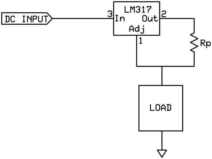
FIGURE 3. By substituting the load for the adjustment resistor, the LM317 becomes a current regulator (the voltage changes according to the load). This is a very useful circuit that is not often used.
It's easily seen that the maximum current allowed depends upon Rp. If Rp is made 1.25W, then up to a full amp of current can be supplied. Note that this current is limited by the 1.5A maximum output of the regulator and the maximum output voltage obtainable (which depends upon the input voltage). This current regulation is a very useful feature (of these regulators) that is not often used.
Power Dissipation
Basically, the regulator acts like a variable resistor in series with the power supply. The amount of power dissipated is simply the voltage difference between the input and output pins times the current drawn. This creates some interesting situations.
For example, suppose you provide 35V to the input of an adjustable regulator and expect to draw one amp at five volts and also at 32V. At five volts, there will be a 30V drop across the regulator. With an amp of current, the regulator will have to dissipate 30W while providing five watts to the load. It’s only 14% efficient. At 32 volts, there will be a three volt drop which means that the regulator must dissipate just three watts while supplying 32W to the load. This is 91% efficient.
It's clear that keeping the input voltage as close to the output as possible results in better efficiency and less heat. (Note that with an input voltage of 35V and a current requirement of one amp, the total power used will always be 35W. The more power the load uses, the less the regulator must dissipate.)
Often times, multiple voltages are needed for a circuit. There is nothing wrong with placing a five volt regulator after a 10V one. In this way, the voltage drop for the five volt regulator is shared between two devices. However, if the two voltages have significantly different current requirements, this approach may not be optimal. (You can use Ohm’s Law to calculate the effective resistance of the regulator given the desired voltage and current. The power is then calculated to be the resistance times the current squared.)
Applying the Theory
We can now combine the information from the two articles to build a practical power supply. We’ll start with a basic supply and then discuss how to change it to add features that may be useful. Figure 4 provides a practical circuit for an adjustable current-limited and voltage-regulated one amp power supply that goes from zero volts to about 30 volts. (This particular circuit has proven to be very useful and adaptable in a number of high-reliability designs for my clients; usually with fixed current limit and fixed output voltage.)
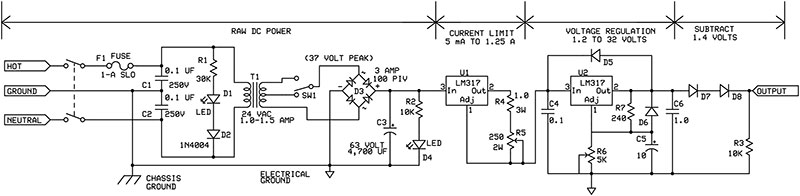
FIGURE 4. This is a nice bench power supply that provides 0-30 volts at one amp. It’s also current limited to help eliminate unnecessary smoke generation in your circuits. Meters to monitor the voltage and current can be added, if desired.
The raw DC circuit was described in detail in Part 1 and will not be discussed further except to note a few minor changes. The power transformer is now specified as a 24 volt center-tapped 1.0 to 1.5 amp device instead of 25.2 volts at two amps. The reason for this change is three-fold.
The first is that some regulators are limited to 35V (most others are rated to 40 V and there is a high voltage version — LM-317H — that can go to 60V). Note that this is technically the voltage differential between input and output, not from input to ground. If the output is maintained above ground, then the input can be higher.
However, for a general-purpose power supply, you must assume the output will be shorted to ground from time to time. This means that the input voltage must be limited to about 37V because there will be about 1.4V dropped by the bridge diode and an additional 2.5V dropped by the current regulator.
Also, there is no reason to provide two amps of primary DC current if the maximum output is rated at one amp. (Note that the rating is less than the absolute maximum the circuit can provide.)
The third reason is for regulator heat control. This is also the reason for the added switch which will be discussed in more detail below.
The main filter capacitor has been reduced from 10 mfd to 4,700 mfd because the power supply current specification has been reduced from two amps to one amp.
The adjustable current regulator is just three parts: an LM-317; a fixed resistor; and a variable resistor. The fixed resistor is necessary to limit the current through the resistor string. Obviously, as the resistance gets lower, more current flows. With a 1.25V differential between the output and adjustment pin, the one ohm fixed resistor limits the current to 1.25A.
If this resistor was eliminated and the adjustable resistor was set to 0.1W for example, the current would be (theoretically) 12.5A (using Ohm’s Law). This would either destroy the IC or cause it to shut down from thermal overload. Neither is good.
Also, the power through that small resistance would be 15.6W (power is equal to current squared times resistance). This would burn the variable resistor. By forcing a minimum of 1.0W in the circuit, the current is limited to a maximum 1.25A and the variable resistor is protected.
The worst case power dissipated by the fixed resistor is 1.25W. A three watt resistor (rather than a two watt device) is chosen to be conservative. The worst case power requirement of the variable resistor occurs when it is equal to the fixed resistor or 1.0W.
In this instance, there will be about 0.4W of power through it. This means that a one watt potentiometer is adequate, but a two watt unit will be used to be very conservative. Remember, it’s better to spend a little bit extra on the power supply than to spend a lot on ruined circuits.
The voltage regulator section is simply the design from the beginning of this article. The only change is to use a variable resistor (R6) instead of a fixed resistor (Radj).
Heatsinking is an important issue. The voltage regulator must be able to dissipate up to 32W of power, worst case. This creates a significant problem. The typical TO-220 case is limited to 15W as per the spec sheet. One poor solution is to reduce the maximum power rating to about 0.5A for lower voltages. This is changing the specs to match the design instead of designing to match the specs. There is another approach that requires a bit of creative engineering that will be detailed below.
Curiously, the current regulator is very efficient. The voltage drop is typically 2.5V (worst case), so the maximum power dissipated at one amp is 2.5W. A simple and inexpensive clip-on heatsink is sufficient here.
Fixing the Heat Problem
As noted, there is too much heat to be dissipated at low voltages. The problem comes from the large voltage drop from the input to the output of the regulator. The solution is to use a center-tapped transformer and switch between taps. Center-tapped transformers are common and generally cost no more than noncenter-tapped transformers.
When the switch is connected to the top end of the transformer, the full voltage is applied to the rest of the circuit and the full range of voltages is possible. As long as the current draw is kept below about 0.5A, there will be no heat problem. However, if the power supply needs to provide a high current at a low voltage, the switch is used to connect to the center-tap and reduces the input voltage by 50%. Thus, only about 18 volts is applied to the rest of the power supply.
So, if five volts at one amp is needed, then only 13W of power must be dissipated by the regulator as heat (instead of about 30W). This allows the standard TO-220 style regulator to be used within the specified limits. (If you want to get fancy, you could monitor the adjustment voltage and use a separate circuit to automatically switch between the transformer windings.)
Fixing the Minimum 1.2 Volt Problem
Most people want a power supply to go all the way to ground. It turns out that there's an easy way to accomplish this: just add two diodes in series with the output. Each diode drops the voltage by about 0.7V (depending on load). So, two diodes will reduce the output by 1.4V. In actual operation, only about 1.0V is dropped at no load. This makes the minimum output no load voltage 0.2V. This is virtually zero.
If you really want to, you can add another diode in series to drop the output further, but it seems unnecessary. The resistor to ground is included to drain off any leakage through the diodes. Without the resistor, the output can float up to the voltage applied to the diodes.
It should be noted that you can pull the output of the regulator to ground if you apply a negative voltage to the adjustment pin. This is somewhat complicated if a negative voltage is not easily available (as in this case). The addition of two diodes is a quick and easy fix.
Minimum Current Discussion
As noted on the schematic shown in Figure 4, the minimum current limit is about 5 mA. For virtually all applications, this is not a problem. Very few components will be damaged with 5 mA applied to them. However, if the voltage is set to 30V, then 150 mW of power is present at the output. This could be too much for some components.
It must be remembered that the voltage regulator uses some current for its operation (in addition to the current dissipated during the process of regulation). As it happens, the regulator draws about a constant 5 mA with a 30V input, regardless of the voltage output setting. Therefore, while the current regulator provides a minimum of 5 mA, this current is used by the following voltage regulator and it is not seen at the output to a great degree (although in certain special cases it might be). This is not a perfect solution, but it is reasonable.
If desired, a larger current adjustment resistor (R5) can be used. A 1K potentiometer will reduce the minimum current out of the current regulator to about 1 mA.
Adding Meters
It’s always nice to be able to measure the voltage output and current used. Adding a voltmeter is simple. Just place it across the output to measure the voltage.
The current meter is a bit more complicated. You can place an ammeter in series with the output to measure the current used. This will work most of the time. The problem is with the series resistance added by the meter. Depending on the meter, this might affect the circuit you are powering. Basically, it increases the power supply impedance. This is especially true for low current ranges where the series resistance may be a hundred ohms or more (my cheap meter has 800W of resistance on the 500 µA scale).
If you don’t mind an error of a few mA, there is a very convenient place to measure the current. All you have to do is measure the voltage across the leads of R4 in the current limiting circuit. This is a one ohm resistor and will provide one volt per amp of output current.
The basic accuracy depends on the precision of the resistor. A 1% resistor will be accurate to 1% except for the few mA used by the voltage regulator circuit that follows. (Note that you can measure small load currents by noting the current before connecting the load and after it has been connected. The difference is due to the load. Your basic limitation here is the ability to measure small voltages. Five mA of current will provide only 5 mV across the resistor.)
The proper method of measuring the output current is to add a small series resistor to the output and measure the voltage drop across it (just like we did with R4). Typically, this resistor is 0.1W or less and requires a bit of careful design. There are current monitor ICs available for a couple of dollars that greatly simplify the problem of converting a current into an easy to measure voltage.
Conclusion
Understanding basic analog power supply concepts allows the design of a robust, general-purpose power supply for around $25. Adjustable three-terminal regulators are inexpensive and their shortcomings can be compensated for without too much trouble. Higher current and higher voltage regulators are available so that larger power supplies can be built.
Instead of providing only a circuit diagram and instructions, these two articles have attempted to provide a foundation of information needed to help anyone design a power supply for their own needs. Power supply design is a basic skill every engineer and hobbyist should have. After all, every project needs to be powered in some way. NV
PARTS LIST
| Resistors 1/4 watt 5% unless otherwise specified |
| R1 |
30K 1 watt |
| R2, R3 |
10K |
| R4 |
1.0 3 watt |
| R5 |
250 2 watt adjustable |
| R6 |
5K adjustable |
| R7 |
240 |
| Capacitors |
|
| C1, C2 |
0.1 mfd 250 volts ceramic |
| C3 |
4,700 mfd 63 volt aluminum electrolytic |
| C4 |
0.1 mfd 63 volts ceramic |
| C5 |
10 mfd 63 volts aluminum or tantalum electrolytic |
| C6 |
1.0 mfd 63 volts aluminum or tantalum electrolytic or monolithic |
| Semiconductors |
|
| D1, D4 |
High efficiency LED |
| D2, D5, D6 |
1N4004 rectifier diode (1 amp 400 PIV) |
| D3 |
Bridge rectifier 3 amp 100 volt PIV |
| D7, D8 |
1N5401 rectifier (3 amp 100 volt PIV) |
| U1, U2 |
LM317 adjustable voltage regulator TO-220 package |
| Misc. |
|
| T1 |
Transformer 24V center-tapped 1.0 amp to 1.5 amps |
| F1 |
1 amp slow-blow fuse |
| SW1 |
SPDT switch (3 amp contacts) |
| Power cord, case, fuse holder, heatsinks, optional meters, etc |