Just when I thought I was done building LED “blinky” things (my house is filled with them), I see something on the Internet that catches my eye and off I go again building something new. To my friends, this is now a standing joke and they, in fact, call me “Mr. Blinky.” Oh well, I could be called something worse.
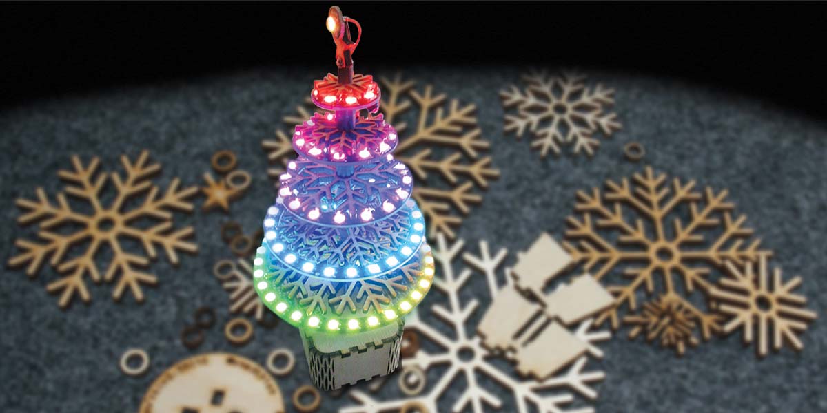
In this case, many things caught my attention, and the result is the NeoPixel LED tree described here.
The NeoPixel LED Tree:
- Is beautifully made from laser cut 3 mm Baltic birch plywood.
- Is powered by a NodeMCU Amica ESP8266 32-bit Wi-Fi enabled processor.
- Has 93 individually addressable NeoPixel LEDs, allowing for a large number of display patterns.
- Is remote controllable from any browser on your Wi-Fi network.
- Has 50 display patterns built in, including some with a Christmas theme.
- Has an Auto mode which randomly selects display patterns so you get a taste of every display pattern the tree has available.
I cannot take credit for much of this design because I basically merged things I found on the Internet together, and with my knowledge of the ESP8266, the result was this project. Specifically:
- I came across the mailable laser cut Christmas tree card project on hackaday.io.
- I found a rather inexpensive set of NeoPixel LED rings (93 LEDs in all) for sale on Amazon.
- I found software that designs laser cut flex boxes. A flex box is used for the base of the tree.
- I found a NeoPixel special effects library for the ESP8266 that provided most of the display patterns, and an example program from the same library that was the basis of the tree remote control program I wrote.
- I used the ESP8266 WiFiManager library to allow the tree to connect to any Wi-Fi network without having to hardcode Wi-Fi credentials into the program. This is very handy when you move the tree between Wi-Fi networks or locations.
- I used the ESP8266 ArduinoOTA (OTA stands for Over The Air) library that allows the tree’s software to be updated wirelessly without having to physically connect a USB cable. This helps prevent damage to the tree because updates are hands off.
Links to all the stuff I found on the Internet are provided in the Resources section.
Laser Cutting Tree Pieces
When I first came across the laser cut Christmas tree card project, I quickly fell in love with it. Each piece of the tree (see Figure 1) is like a snow flake made from wood. Also, the light color of the Baltic birch contrasted nicely with the brown burn marks caused by the laser cutter, which brings me to the laser cutter. Where was I going to find one to use or was I going to have to pay some company to cut the tree out for me?
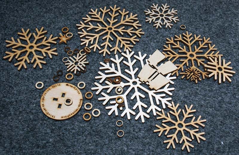
FIGURE 1. Laser cut tree parts resemble wooden snow flakes. As noted in the text, not all pieces are used.
Luckily, it was brought to my attention that many of the public libraries in the Pikes Peak region where I live have Maker Spaces with laser cutters (and a lot of other equipment) that are available to the public to use under the supervision of library staff. This was fantastic in that not only was I using the laser cutter free of charge (you must supply your own materials), but there were knowledgeable and friendly staff on hand to help me get going.
In preparation for using the laser cutter, I was given a quick talk on safety and shown around a display that presented the many different materials the laser cutter can be used on, including: stone, brick, wood, paper, plastics, fabric, etc. I may try to engrave some stones later for Christmas presents.
With the prerequisites out of the way, my library card was stamped allowing me to use the Maker Space equipment whenever it is open. When I then saw the Epilog Zing laser cutter (see Figure 2) in action, I immediately gained an appreciation for the capabilities and the precision possible with this device.
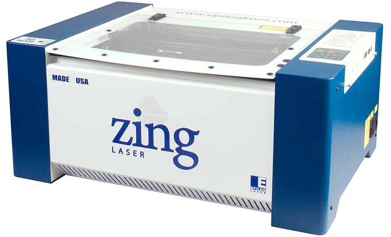
FIGURE 2. Epilog Zing laser cutter. Available for public use at my local library, and maybe yours too.
The library’s Epilog laser cutter is driven by a program called Corel Draw which I thought was long extinct, but I was mistaken. Current versions of Corel Draw have many features that make it suitable for driving a laser cutter. I have been successful in using design files in both svg and ps (postscript) formats with the program.
Using Corel Draw with the laser cutter is pretty easy once you have done it a few times. I had some initial issues, but got them worked out with the help of the library staff. The Epilog laser cutter comes with a handy chart that tells you how to set the power level and the laser speed for the materials you are using. The 30 watt laser easily cuts through the thin birch plywood used for the tree, and is amazing to watch.
You’ll notice a question mark for quantity in the tree assembly Parts List. The reason for this is the laser cut flex box base is very fragile due to the flexible corners the boxes have, so I ended up having to cut five of these before I got one that didn’t break during assembly.
The secret is to completely soak a paper towel with water and then wrap the three pieces that make up the box together and place them in a microwave for about a minute. Set the wrapped wood aside for a couple of minutes after removal from the microwave to allow the plywood to thoroughly steam before attempting assembly.
Next, very carefully stretch and hold the long piece that makes up the box sides a couple of millimeters to widen the wooden corners. Then, proceeding very slowly, wrap the side piece around the bottom piece, locking the tabs in place as you go.
Once you get the wrapping done, place the top piece onto the box, and set the box aside and allow it to dry completely before proceeding. Once the box is dry, it will retain its shape so you can take the top or bottom off to work on the electronics that will be placed inside.
I believe the small size of the flex box base is partially responsible for its fragility. Larger flex boxes probably wouldn’t be quite as fragile because there would be more material in the flexible corners. I have included the postscript design file for these flex boxes in the zip file available at the article link. The general design file called flexbox_v.1.3.ps can be opened in any text editor and the boxlength, boxwidth, and boxheight variables can be changed to produce boxes of any size.
I have also included treebase.svg which is the design for the tree base used here. This file was created by copying flexbox_v.1.3.ps to a different file, opening it up in a text editor, and then setting the user defined parameters as follows:
% Define box parameters — This is the size of the box you want
/boxlength 3.0 inch def % long dimension of flat side of the box
/boxwidth 1.5 inch def % dimension across the hinge
/boxheight 2.5 inch def % short dimension across flat side of the box
/cornerradius 0.5 inch def % radius of the hinge
/materialthickness 0.125 inch def % thickness of the material which will become the box
I then used a free online service to convert the modified postscript file to an svg file because I thought that was necessary for use with Corel Draw. I have since discovered Corel Draw can work just as well with the original postscript file, so no conversions are necessary. The design for the base is shown in Figure 3.
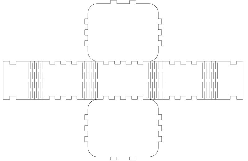
FIGURE 3. Tree base design. Base is 3” wide x 2.5” deep x 1.5” tall and is laser cut from 3 mm Baltic Birch.
Laser cutting the tree was much easier and successful on the first attempt. I cut two copies in case I damaged any of the pieces. The design for the tree is shown in Figure 4.
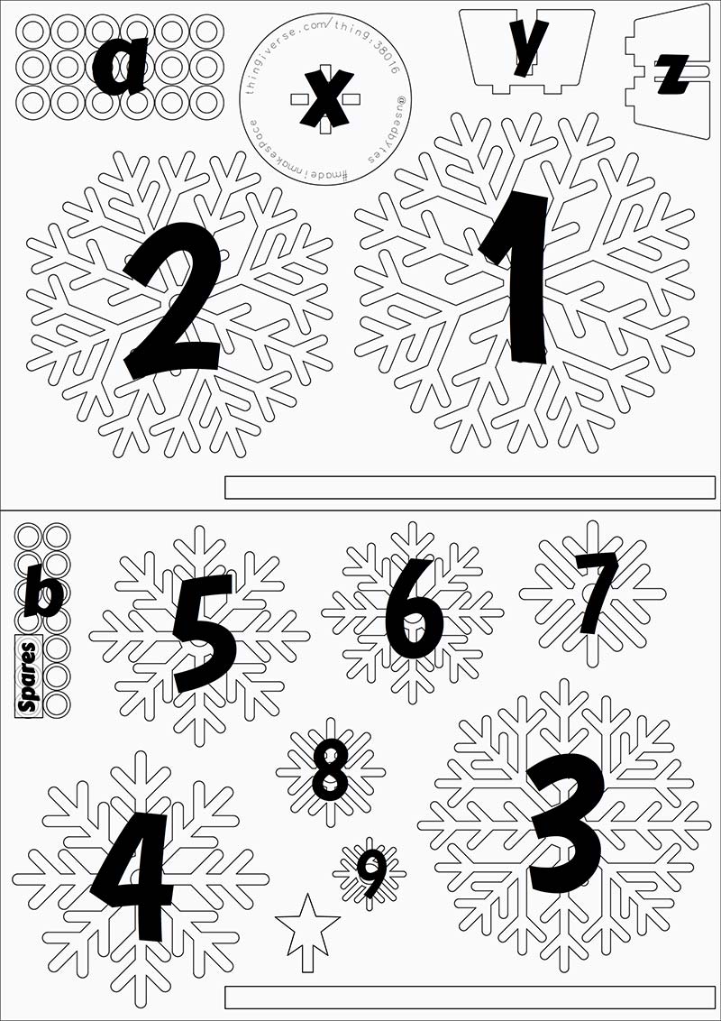
FIGURE 4. Tree design from Thingiverse.com with items labeled.
Once cut, the tree pieces are fragile and need to be handled with care. I should note that not all of the pieces from the tree design are used in the NeoPixel LCD tree. Only sections 1, 3, 4, 6, and 8, and the star are used. The other laser cut pieces could be used for Christmas tree decorations or perhaps even earrings.
| Quantity |
Description |
Size |
Source |
| 2 |
Baltic birch for tree. Half of the tree is laser cut from each piece. |
6” x 8” |
Woodcraft, Home Depot, Lowe’s, or any wood supply store |
| ? |
Baltic birch for the flex box used for the base of the tree. |
6” x 10” |
Same as above |
| 1 |
Round aluminum tube 6 mm outside diameter. |
About 5-3/4” long |
eBay, Hobby shops |
Parts List — Tree Assembly
The Electronics
The electronics used in the tree couldn’t be much simpler nor easier to put together.
The NeoPixel ring set is shown in Figure 5. The schematic for the tree electronics is shown in Figure 6.
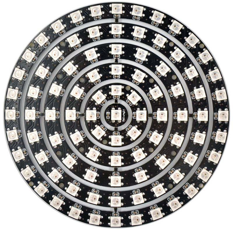
FIGURE 5. NeoPixel ring set from Amazon.
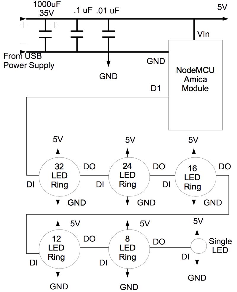
FIGURE 6. Schematic diagram.
| Item |
Description |
Source |
| NeoPixel ring set |
Mokungit 93 LEDs WS2812B WS2812 5050 RGB LED ring lamp light with integrated drivers. Includes rings of 32, 24, 16, 12, and 8 LEDs, along with a single stand-alone LED. |
Amazon |
| NodeMCU Amica module |
32-bit uC with Wi-Fi interface |
Electrodragon.com |
| USB power supply |
Capable of 5 VDC @ 2.5 amps minimum |
Amazon, RadioShack |
| Capacitor |
1,000 µF @ 35 volts |
RadioShack |
| Capacitor |
.1 µF |
RadioShack |
| Capacitor |
.01 µF |
RadioShack |
Parts List — Electronics
Building the Tree
Before beginning assembly of the tree, the tree sections are glued to the NeoPixel rings as shown in Figure 7. I glued the single NeoPixel to the tree’s star as well. I should note that the center hole of each tree section is slightly smaller than the 6 mm support tube. I used a reamer to carefully enlarge each hole to allow them to slide down the tube into position.
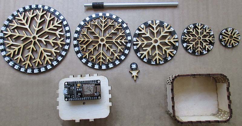
FIGURE 7. LED rings attached to tree segments with Goop™ glue. NodeMCU Amica device glued to base top as well. Base itself doesn't require glue to hold together.
The tree is built from the base up. I started by fitting parts X, Y, and Z together which make up the tree’s support structure. I used a small file to slightly taper the tabs so they would fit into the round disk X. With that done, I glued the round disk to the top of the flex box, and then glued parts Y and Z to the disk. I inserted the support tube into this assembly to keep the parts correctly aligned while the glue dried.
Once dried, I drilled a small hole in what will be the back of the tree (Figure 8) for the three wires that connect the NodeMCU module in the base to the large NeoPixel ring which makes up the first tier of the tree.
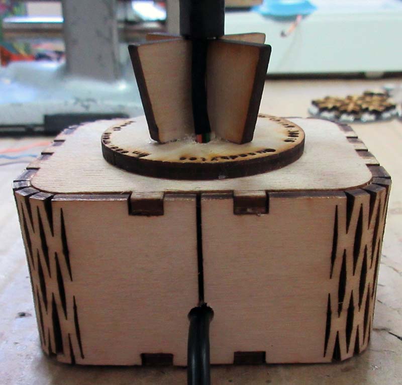
FIGURE 8. Tree base detail. Note the hole into the base for the wires. Heat shrink tubing is used to hide the wiring. USB power supply wire extruding through the hole in back of the base.
Within the base, I glued the NodeMCU module in place, and then wired up the electronics as shown in Figure 9. With that done, I reassembled the flex box base so it could support the tree as it was being built.
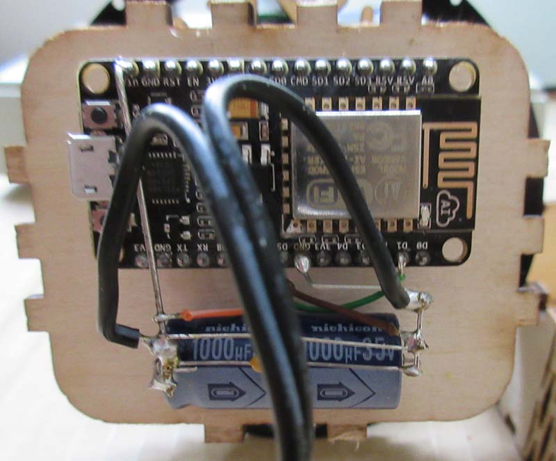
FIGURE 9. Base electronics. Black wires from USB power supply.
The tiers of the tree are separated using laser cut spacers “a” and “b,” where the a spacers have a slightly larger outside diameter than the b spacers. I used a spacers towards the bottom of the tree and b spacers towards the top. I used five spacers between the base and the first tier; seven between the first and second tiers; seven between the second and third tiers; six between the third and fourth tiers; five between the fourth and fifth tiers; and another five between the fifth tier and the star.
I covered the spacers and wires between the tiers of the tree with heat shrink tubing because it is important to hide the wires as much as possible. Figure 10 shows this in detail. The spacers had to be reamed so they would fit over the support tube.
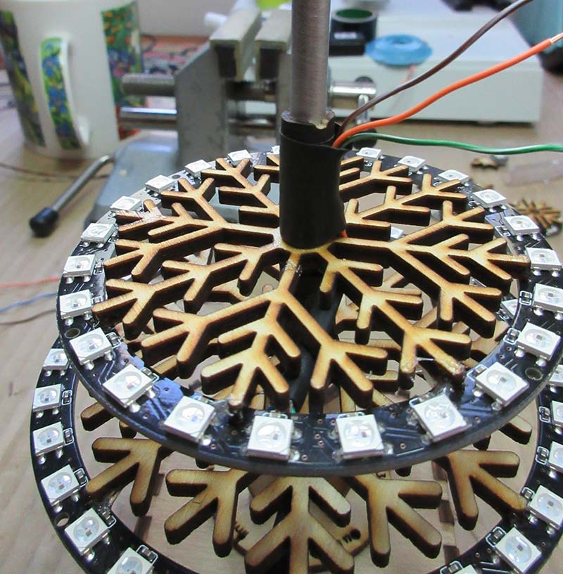
FIGURE 10. Assembly detail close-up. Heat shrink tubing used to hide spacers and wiring between sections.
Wiring the NeoPixel rings neatly was somewhat difficult to do. Four wires must be soldered onto the little pads of the NeoPixel rings. Each ring has a data input pad (DI), a 5V pad, a GND pad, and a data out (DO) pad. The DO pad of a lower ring must connect to the DI pad of the upper ring, and the 5V and GND connections are paralleled all the way up the tree. The DO of the eight NeoPixel rings is wired to the DI pad of the single NeoPixel LED glued to the tree’s star. There is no connection from the single NeoPixel LED’s DO pad. Care must be taken when soldering these connections because it’s very easy to lift these pads if too much heat is applied.
Tree Software
The software for the NeoPixel LED tree was developed using the Arduino IDE (integrated development environment). I used version 1.8.0 for Mac OS, but you should be able to use the Arduino IDE on Windows as well. See my previous articles in Nuts & Volts or the Resources section here for how to set up the Arduino IDE on your computer for targeting ESP8266 type devices.
To use the OTA feature of the Arduino IDE, you must allow the IDE to accept remote connections. How this is accomplished varies depending on the computer platform you are running on, but usually involves a change to your computer’s firewall settings. Google “Enabling Arduino OTA <your platform>” to get the instructions appropriate for your computer.
The NeoPixel LED tree software is available in the downloads. To use this software, unzip the file and copy/move the ESP8266NeoPixelTree directory into your computer’s Arduino directory. The zip file also contains the versions of the libraries I used during program development. It’s important to use these versions as different ones may not function correctly. These library zip files should be unzipped and then moved into your Arduino/Libraries directory for use. It is best to install new libraries before the Arduino IDE is started.
Whereas the electronics for this NeoPixel LED tree borders on the trivial, the software/firmware for the tree is a bit more involved. The files which make up the program are described in Table 1. In addition to the files in Table 1, the Arduino libraries that are required are listed in Table 2.
| File |
Description |
| ESP8266NeoPixelTree.ino |
The main program file that drives the NeoPixel LED tree. |
| index.html.h |
Miscellaneous HTML snippets that support the web UI. |
| main.js.h |
Javascript functions used in the web UI. |
TABLE 1.
| Library |
Function |
Source |
| ArduinoOTA |
Allows the NeoPixel LED tree code to be remotely updated after the initial upload. |
Provided with the ESP8266/Arduino platform code. |
| WiFiManager |
Allows the NeoPixel LED tree to change Wi-Fi credentials without having to make a code change. |
https://github.com/tzapu/WiFiManager |
| WS2812FX |
A NeoPixel LED special effects library for the ESP8266. |
A modified version of this library is included in the article download. |
TABLE 2.
Once you have the code and libraries in place, you must connect the NodeMCU device in your tree to your computer using a USB cable. Next, select the NodeMCU 1.0 board type from the Arduino IDE and the port that is used to connect to your NodeMCU device. Once that is completed, you can compile the code. If it’s error-free, you can upload the code to your tree.
Once this initial upload is successful, you can disconnect the USB cable and do any further updates remotely.
Remotely Controlling the Tree
Before you can remotely control the NeoPixel LED tree, you must first provide Wi-Fi credentials so the tree can connect to your local network. If the ESP8266 has not been connected to the Wi-Fi network previously, it will create a wireless access point called NeoPixelTreeAP that you must connect to with your computer.
Once that is done, with a browser go to 192.168.4.1 and you will be presented with a page for assigning credentials. When you click on the SSID of your network and then specify the password, the ESP8266 should take down the access point and attempt to establish a connection to your Wi-Fi network. You can monitor the status of this process if you have the Arduino IDE’s serial monitor open.
Once you establish a connection to the Wi-Fi network, the ESP8266 will remember the credentials going forward. You should never have to go through this process again, unless you move the NeoPixel LED tree to another network or location.
With Wi-Fi setup complete, change your computer back to your normal Wi-Fi network and navigate your browser to 192.168.0.3. If all is well, you should see the web page (Figures 11 and 12) you will use to control the NeoPixel LED tree.
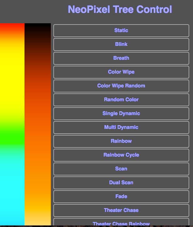
FIGURE 11. Top portion of web UI for controlling NeoPixel LED tree.
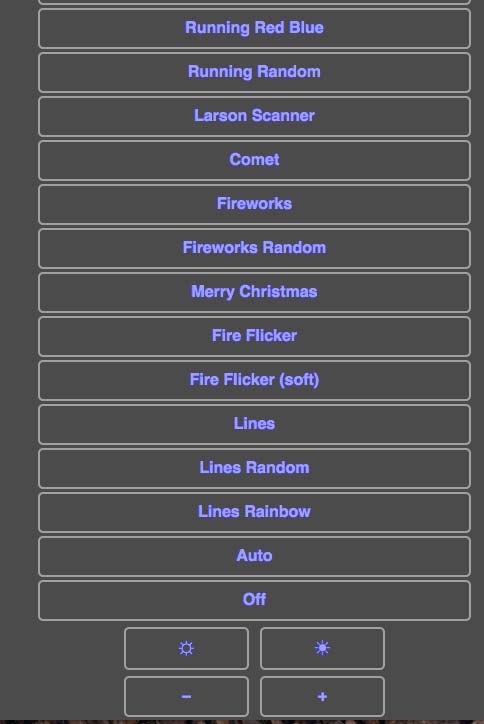
FIGURE 12. Bottom portion of Web UI for controlling NeoPixel LED tree.
In the middle of the page is a long list of display pattern buttons that you can click on. If a display mode allows its color to be configured, you can click on the hue strip on the left to set a color; you can then click on the middle strip to set the color’s saturation.
At the bottom of the page, you can change the overall brightness of the tree and the speed at which the display patterns run. The Auto mode selects a new display pattern randomly every 30 seconds. It also selects a random color, random brightness, and random speed the display pattern will run with. The Off mode makes the tree appear to be off, but it is still listening for display pattern changes from the UI (user interface).
Final Thoughts
Does the world need yet another blinky thing? Probably not, but that’s never stopped me from building anything. The NeoPixel LED tree is a beautiful addition to my collection of blinky things and would make a great gift for someone who likes such items.
Show a child how to control the tree via a browser and watch them sit for a long time clicking the screen and seeing what the tree does. It surprised me initially how fast the tree reacts to changes made in the browser; it is virtually instantaneous. Even without the LEDs lit up, the laser cut tree is kind of nice to look at as the wood has nice burned edges.
In its current form, the NeoPixel LED tree is for decoration/fun only. There may be, however, some serious uses for such a device. The tree could be used as a night light in a child’s room. With changes to the software, the tree could be used for the “Thinking Of You” device I wrote about in the November 2015 issue of Nuts & Volts. It could also be repurposed as a display showing whether the stock market is up or down. It could be programmed to remind you when it’s time to stand up and take a break or to go home from work. The possible uses are almost endless.
This was a fun (though rather challenging) project to build; mainly as a result of never having used a laser cutter before, and the problems I had with the flex box base. I learned a lot about using a laser cutter that I’m sure I can apply to future projects.
I also learned that I would like to own a laser cutter, but that is another issue all together. NV
Downloads
What’s in the zip?
Source Code
Assembly Instructions And Resources For The Tree