I don’t have much in the way of graphic arts skills. I can draw a stick figure, but painting an actual picture is beyond me. With a little help from a microcontroller, I decided I could get around this lack of skill and create simple impressionist-style light “paintings” that would change over time to keep them interesting. The Digital Impressionist (Figure 1) is straightforward to build, easy to program, and readily customized or hacked to make even more intricate and varied paintings.
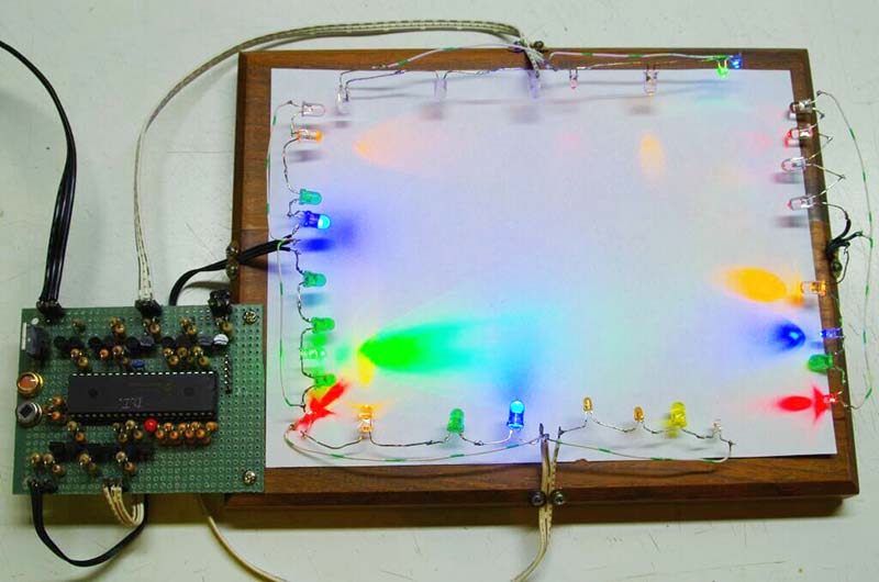
FIGURE 1. The prototype Digital Impressionist showing the “canvas,” LED arrays, and controller circuit.
This project uses a PIC16F887 microcontroller to drive eight channels of LEDs: one each for red, yellow, green, and blue, and four multi-colored strings. The schematic in Figure 2 shows only one of these channels for clarity, consisting of D1-D4, R1-R5, Q1, and Q2.
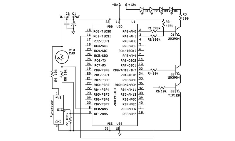
FIGURE 2. Digital Impressionist schematic.
R1 through R3 and Q1 allow the ultimate brightness of each channel to be set independently, and the PICBASIC PRO code for the project (available in the downloads) randomizes the state of the PortA and PortD pins to change the channel brightness before each painting. R4 and Q2 allow each channel to be faded in independently under software PWM (pulse-width modulation) control via PortB, and the code also randomizes the order that the channels are activated. R5 limits the current through the LEDs.
Since this project paints with light and not pigments, the overall brightness of the painting must be adjusted based on the ambient lighting conditions so it doesn’t wash out in a bright room or overpower in a dim one. R10 is a cadmium-sulfide photoresistor that forms a voltage divider with R8 to tell the PIC how bright the room is via an internal analog-to-digital converter (ADC) on input PortE.0. The code uses this information to set the duty cycle of the PIC’s hardware PWM Channel 2 on PortC.1 and drive Q3 — a Darlington power transistor that acts as a master brightness control for the entire painting.
Q3 is also used to fade out the entire painting before a new one starts.A real painting appears the same whether someone is looking at it or not, but for this project, there’s no need to paint if no one is there to appreciate it. The pyrometer connected to the PIC’s analog input PortE.1 detects when a person moves near the “canvas,” and starts the code loop to create a new painting. New paintings will appear at intervals until the art aficionado (or critic) moves away. The construction technique for the driver circuit is not critical, and is readily implemented in point-to-point fashion on a piece of Vector board (Figure 3).
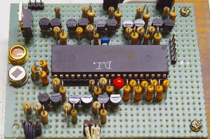
FIGURE 3. Close-up of the controller circuit, showing the light sensor (gold) and pyrometer (silver).
I recommend including an ICSP header (not shown in Figure 3 for clarity) so you can easily fine-tune the code to your liking once your Impressionist is assembled.
Construction of the LED channels around the canvas is also non-critical, but selection of the LEDs themselves is key to getting the painting effect that you want. While I’ve specified part numbers for each color of LED in the Parts List, I found the paintings to be much more interesting when using scavenged LEDs from my parts collection that have a variety of brightness, beam widths, and hues.
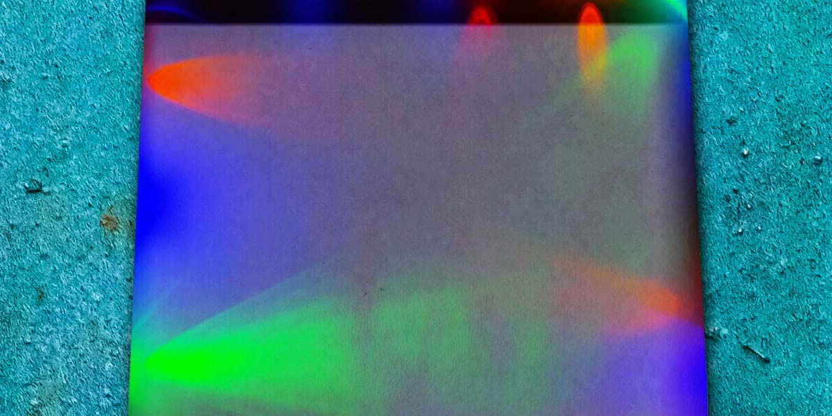
Mixing water-clear and diffused LEDs also adds interest (Figure 4).
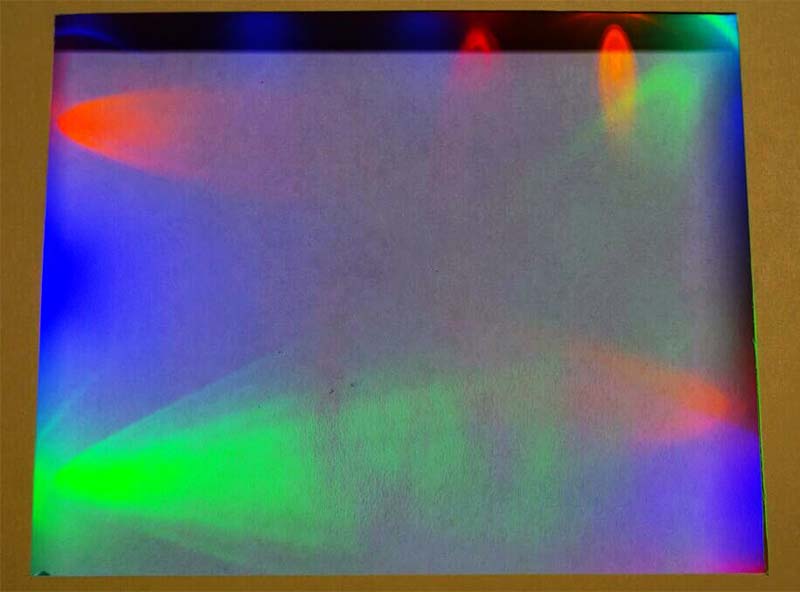
FIGURE 4. The Digital Impressionist at work.
Experiment with the placement of each channel around the canvas and the orientation of each LED within a channel to change the character of your paintings. Note that for an all-blue LED channel, only three LEDs should be used rather than the four in the other channels in order to get a reasonable brightness (due to their higher forward voltage drop).
To upgrade your Impressionist’s paintings to “museum quality,” try some of these modifications:
- Add two more LED channels on the unused pins of PortC to display other colors.
- Attach one or more of the LED channels to servo motors and use additional software or hardware PWM signals to adjust their position between (or during) paintings. Refer to this Spin Zone article for a discussion of code to “walk” the servo outputs so that several servos can be controlled simultaneously in software without a dedicated servo controller.
- Use a patterned or textured surface instead of a smooth white canvas.
- With the Impressionist flat on a table, place prisms, lenses, mirrors, or other glass objects on the canvas to create a kaleidoscope-like effect.
- Add a pause button so that a particularly attractive painting can be displayed indefinitely.
Then, display your newest Impressionist painting for all to see! NV
PARTS LIST
| PIC16F887 microcontroller, DIP-40 |
|
| (16) 2N3904 transistors, TO-92 package |
|
| TIP120 transistor, TO-220 package |
|
| (8) Red LEDs, T1 3/4 package |
|
| (8) Yellow LEDs, T1 3/4 package |
|
| (8) Green LEDs, T1 3/4 package |
|
| (7) Blue LEDs, T1 3/4 package |
|
| (11) 10K ohm resistors, 1/4 watt |
|
| (9) 100K ohm resistors, 1/4 watt |
|
| (8) 270K ohm resistors, 1/4 watt |
|
| (8) 470K ohm resistors, 1/4 watt |
|
| (8) 100 ohm resistors, 1/4 watt |
|
| CdS photoresistor |
|
| Pyrometer |
|
| 47 µF 16V capacitor |
|
| 0.1 µF 50V capacitor |
|
Downloads
What’s in the zip?
Source Code
Schematic