As the last notes of the song ring out, it’s only seconds before the next song starts. You’re the band’s keyboard player and a bead of sweat is on your brow as you quickly glance at the set list, pick the instrument settings, remember to transpose, tweak the volume, set the keyboard splits, and then begin to play. You make it but only just! A look from the impatient drummer says it all! As the song continues, your mind wanders to how you wish it was all easier ... how you’ve always wanted to add some strings and bass to the song but can’t ... the frustration of only having two hands ... (cue dream sequence).
The MIDI Replay Stomp Box (fondly shortened to ‘the Box’) is born from this very experience and more than delivers on the dream. It is both a MIDI configuration tool for applying a song’s keyboard settings, plus a four-track recorder providing accompaniment for songs. Other features include foot-switch control, looping, transpose, keyboard splits and layers, a metronome, plus syncing data with its own PC desktop app and writing to standard MIDI files.
MIDI — The Enabler that’s Taken for Granted
It’s likely you have heard of MIDI (Musical Instrument Digital Interface). It lets musical and computing devices communicate in a common language, and has existed since the 1980s. However, it seems there is little acknowledgement or reflection on what a profound ‘enabler’ MIDI has been.
It’s staggering what MIDI has done for music. Any post-70’s pop song is likely to have involved MIDI. Music ‘sequencers’ which tie all the tracks of a song together all use it. Almost all musical keyboards and devices have MIDI sockets that let them talk to each other.
The underlying concept of a ‘common language’ is so powerful. Human evolution exploded because of it. This project wouldn’t be possible without it. When the first, beautiful, musical score of a recording effortlessly ‘fell out’ of the MIDI Replay Box via a sequencer, it seemed like a ‘free lunch’ — too good to be true!
MIDI is also profound in that it’s about the ‘control’ of music rather than the ‘audio’ itself. It’s like recording the actions of the musicians rather than the sound they produce. That’s clever: You can edit notes, durations, tempo, transpose, even instruments used — all without having to re-record anything! Plus the storage of ‘actions’ is tiny compared to recording audio.
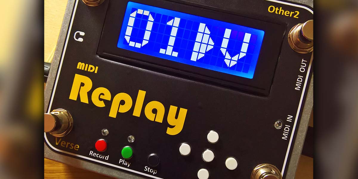
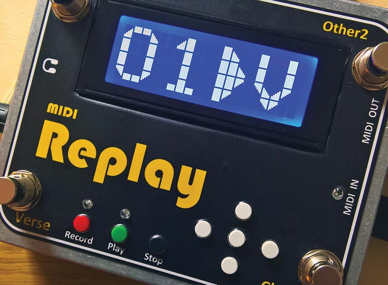
Figure 1 shows the Box in Performance mode; Figure 2 in Edit mode; and Figure 3 looks inside the Box.
■ FIGURE 1. The MIDI Replay Stompbox.
■ FIGURE 2. The Box being used in Edit mode.
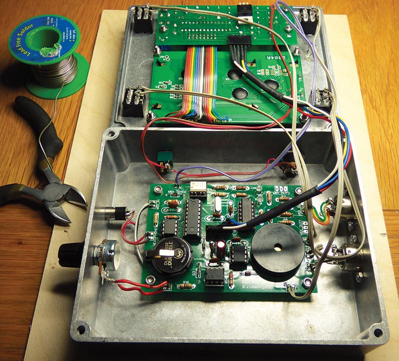
■ FIGURE 3. Opening the Box.
At the heart of the system is a PIC16F648A microcontroller, with its main job being to process MIDI messages. Data is stored in an external battery-backed SRAM (Static Random-Access Memory). Three other microcontrollers handle the user interface, foot-switch control, and metronome. All microcontroller software is written in C, using Microchip’s MPLAB IDE (integrated development environment) and the XC8 compiler.
How It Works — Plug and Play
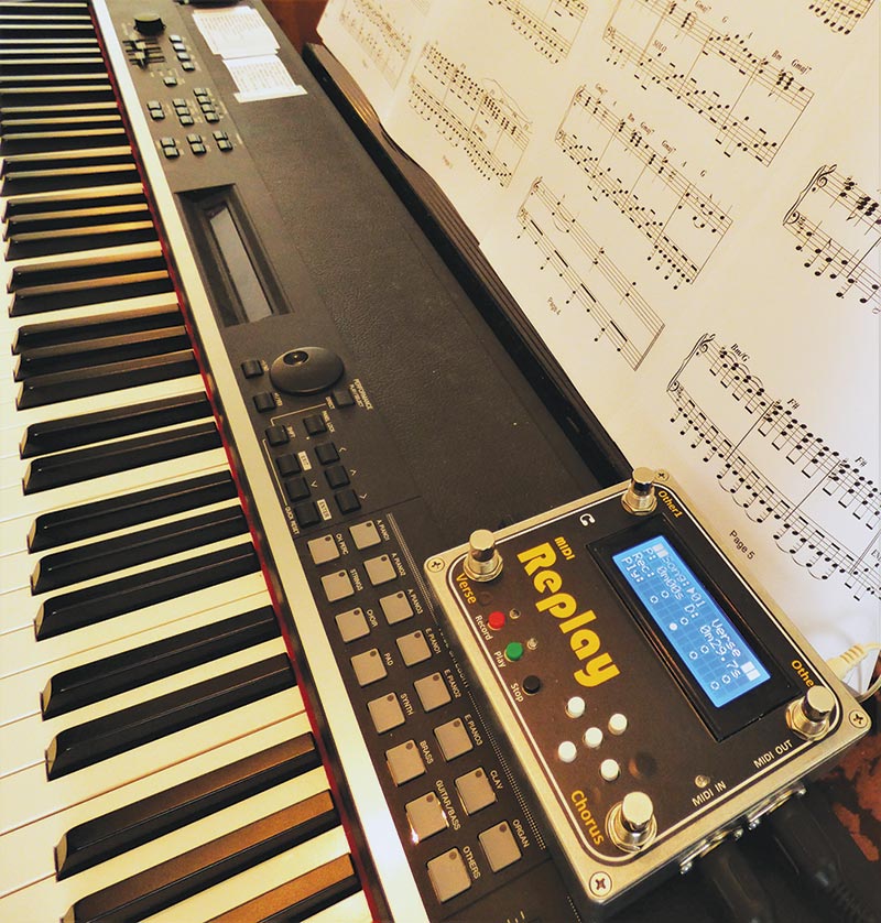
The Box simply interfaces to any MIDI compatible keyboard instrument via two MIDI cables in a loop-back configuration. This is shown in Figure 4.
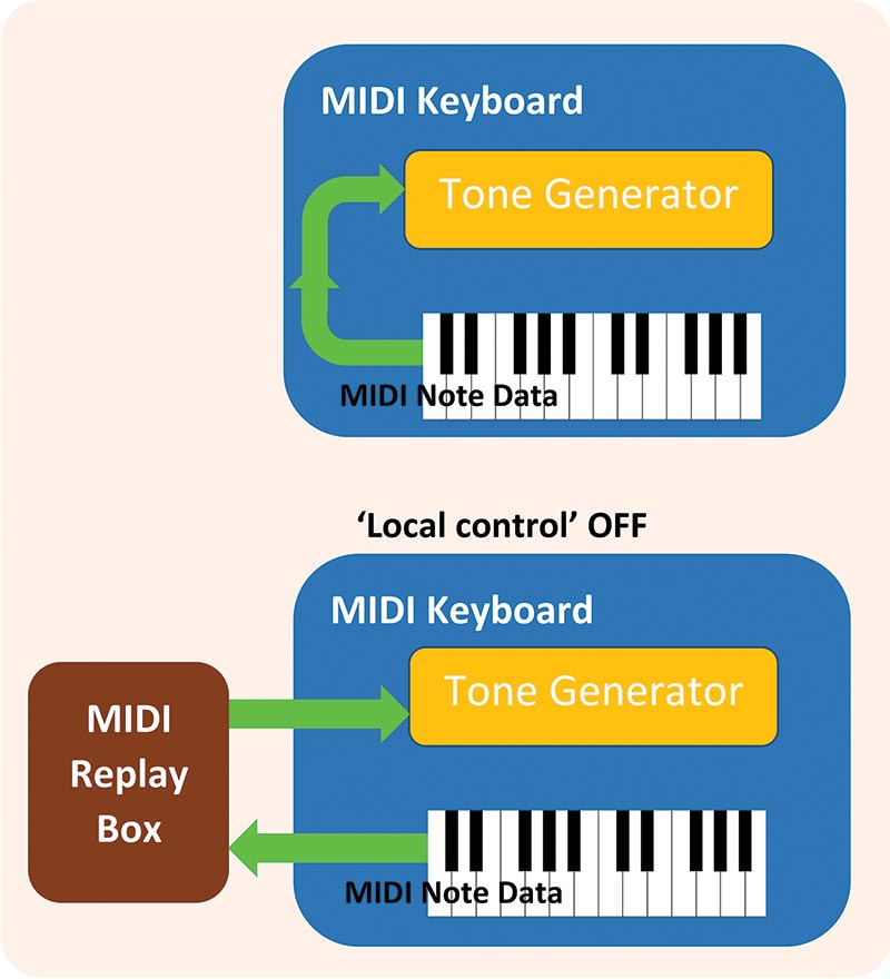
■ FIGURE 4. How the Box is used.
Keyboard instruments have a keyboard controller and tone generator inside. The keyboard controller recognizes all user input via the keys, buttons, sliders, and so forth, then sends the relevant MIDI messages to the tone generator which creates the sounds. This is called local control and is usually a setting accessible via the keyboard’s configuration screen.
Local control must be turned off when the Box is used. The Box receives MIDI messages from the keyboard (keyboard controller) and sends messages back (to the tone generator). The flexibility of MIDI means you are not limited to using the internal tone generator and can connect to other sound modules or keyboards if you wish.
With a set list of songs loaded on the Box, you tap a foot-switch to configure the keyboard for a song. Another click, and the Box plays a section of recorded backing to accompany your real time performance. A ‘Life on Mars’ example MP3 has been recorded on the Box and can be played below. The piano track can be muted, and the strings used as backing.
The Box has a Performance mode (Box on the floor) and an Edit mode (Box on the desktop or keyboard-top). Editing is via buttons and performing is via foot-switches. In Performance mode, the display is in large font.
Logically Speaking — A Dynamic Duo
Figure 5 shows the logical system diagram, consisting of a user interface and MIDI controller. Communication between the two is inter-woven in real time.
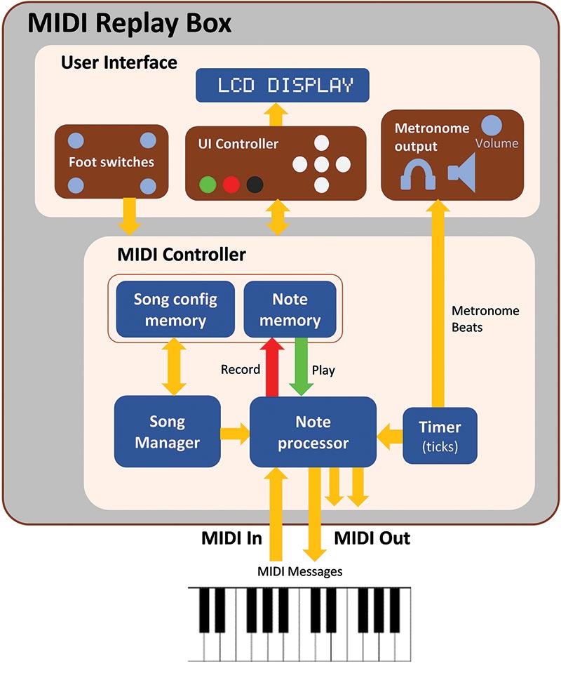
■ FIGURE 5. The logical diagram.
The MIDI controller contains a Song Manager and Note Processor with supporting memory and timer. The memory stores notes and song configuration data. The timer controls beats and song position.
The user interface has buttons and a display, plus a metronome with speaker, headphone output, and associated volume control. The metronome is used to give vital timing cues when using backing.
Musically Speaking — A Best Buddy
The musical diagram in Figure 6 gives an overview from a musical perspective and summarizes the ‘dream’ of the project. To a musician, the Box makes life much easier and presents exciting possibilities.
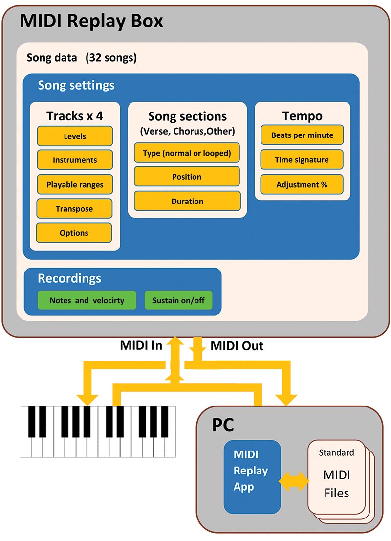
■ FIGURE 6. The musical diagram.
Internally, the Box contains song settings and recordings. Each song has four tracks on separate MIDI channels. For each track, you can set the level, transpose, instrument, and playable range.
In Performance mode, the language of the Box is simply ‘songs,’ ‘sections,’ and ‘start/stop.’ Having the configuration of a song taken care of at the click of a foot-switch is quite a luxury!
Externally, the Box interfaces not only to a keyboard but also to the MIDI Replay app for Windows™.
Figure 7 shows a musical score generated by a free sequencer called Anvil Studio, from a track recorded on the Box.
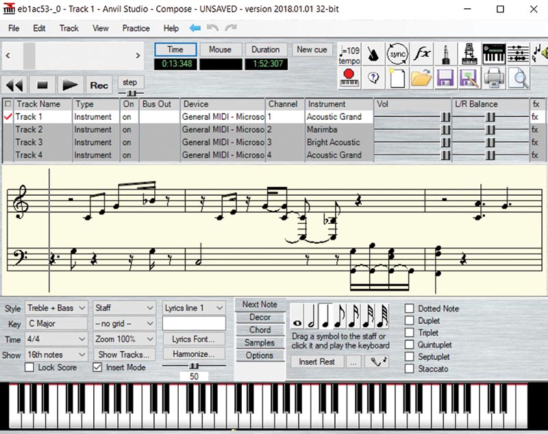
■ FIGURE 7. From Box to standard MIDI file (seen through Anvil Studio).
Figure 8 shows an example of how ranges can be used for splits and layers.
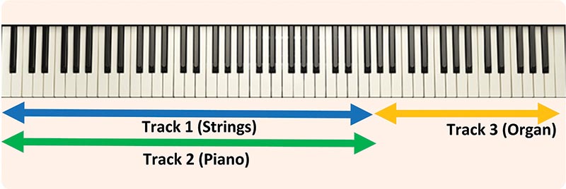
■ FIGURE 8. At the touch of a button: Keyboard splits and ranges.
MIDI and the Horror of Stuck Notes
Any keyboard player experienced with MIDI knows of the dreaded ‘stuck note.’ This is where a note has been sounded via a ‘note on’ MIDI message but the corresponding ‘note off’ message has gone AWOL due to system malfunction.
If the instrument being played is one without natural decay — such as an organ or strings — then the stuck note will sound indefinitely. In a live performance scenario, this can be extremely embarrassing and stressful, with a frantic search for the off switch or ‘all notes off’ MIDI panic button!
Design Challenges of a Real Time MIDI System
So, how do we turn this logical and musical overview into a reliable high-performance system? The stakes are high because system failure mid-performance could be very embarrassing!
This is a real time system with a demanding spec: The notes a musician plays must be processed seamlessly and without delay, applying range and transpose logic, echoed out on selected channels, and possibly recorded. At the same time, any previously recorded tracks might also play back. We know that ‘without delay’ is not possible. The key words that come to mind are latency, accuracy, and precision. For a good musical experience, latency must ideally be 10 milliseconds or less, timing accuracy similar, notes must never ‘stick,’ and the user interface must be snappy and reliable.
Note Latency and What Human Beings can Detect
Latency is the delay between pressing and hearing a note. This is a delicate topic with hot debate over what level is noticeable, but it’s commonly accepted that less than 10 milliseconds is not. One thing to reflect on is that sound waves take 10 ms to travel 12 feet in distance!
Hardware based MIDI devices (dedicated lumps of kit) often have a performance edge compared to software based ‘virtual’ devices because the hardware can be honed and crafted to minimize latency. A PC musical app competes against all sorts of background processes, including very mundane ones such as checking for email or updating the antivirus definition.
It helps to think about a likely worst-case scenario rather than an absolute worst-case. For example, a likely worst-case recording scenario is not tripping onto the keyboard and playing every note simultaneously! Rather it’s probably recording 10 to 20 notes per second for ‘busy’ music, down to almost nothing for very sparse music.
Taking this pragmatic approach, if we occasionally drive the system beyond this likely worst-case and introduce additional hardly noticeable delay, then so be it!
Suddenly, this project begins to look within the reach of a modest mid-range microcontroller.
The Physical Design
The end result after much thought and practical consideration is the physical design depicted in Figure 9.
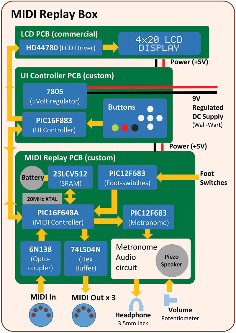
■ FIGURE 9. The physical diagram.
The design has three printed circuit boards (PCBs): a MIDI replay PCB; a user interface PCB; and an LCD display PCB. As in any electronics project, the choice of each microcontroller is a balance of many factors including: the tasks to perform; the component cost; ease of use; features; physical size; code capacity; and memory capacity.
The user interface PCB responds to button pushes and drives the LCD display. As a PCB, it’s relatively simple. It also holds the overall voltage regulator for the system.
The LCD display PCB contains a standard 20x4 character display and uses the ubiquitous Hitachi HD44780 LCD controller. The interface to the PCB is parallel to improve performance.
The MIDI replay PCB is worthy of greater discussion.
The MIDI Replay PCB — the Core Module
This is the core of the system and is a module by design, so it can be used in other systems. A photo of the PCB is shown in Figure 10.
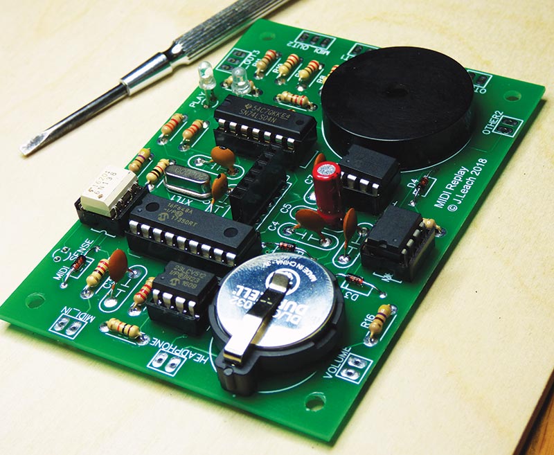
■ FIGURE 10. The MIDI replay PCB.
The PIC16F648A processes everything MIDI related. An associated 20 MHz crystal drives its clock at full throttle. A 23LCV512 high speed battery-backed SRAM device is used to store note data and song configuration data. Two smaller PIC12F683s process the foot-switch messages and the metronome beats. A 6N138 opto-coupler shapes the incoming MIDI signal into a digital waveform.
Finally, an audio circuit filters and outputs the metronome Pulse-Width Modulated (PWM) ‘beats’ via a piezo speaker and headphone socket.
Apart from MIDI, all communication with the board is via commands that control recording, playback, and other functions. There are 26 commands in total. The communication protocol is straightforward and can be bit-banged from any microcontroller.
The full circuit diagram is provided. You’ll notice that there are three MIDI outputs (each with double-inverter buffers). Having three is useful if you want to output to multiple physical MIDI devices.

■ MIDI Replay schematic.
MIDI Replay Parts List
| Item |
Name |
Value |
Notes |
| 23LCV512 |
512 Kb SPI Serial SRAM with Battery Backup |
23LCV512 |
Probably good idea to have an associated DIL socket in case RAM ever needs replacing (although it shouldn't). |
| 74LS04N |
Hex Inverter |
DM74LS04N |
|
| B1 |
Horizontal Lithium Battery PCB Mounted Holder for CR2032 Battery |
|
Check pin spacing to ensure it fits with PCB holes. |
| C1, C2 |
Capacitor |
33 pF |
|
| C3, C4, C6, C7 |
Capacitor |
100 nF |
|
| C5 |
Capacitor |
10 µF |
Important that it's bipolar because it needs to cope with reverse voltage. |
| D1, D2, D3, D4 |
Diode |
1N4148 |
|
| FOOTSWITCH |
Footswitch Microcontroller |
PIC12F683_P |
Recommend an associated DIL socket so that this chip can be reprogrammed if necessary. |
| METRONOME |
Metronome Microcontroller |
PIC12F683_P |
Recommend an associated DIL socket so that this chip can be reprogrammed if necessary. |
| MIDI |
MIDI Controller Microcontroller |
PIC16F648A_P |
Recommend an associated DIL socket so that this chip can be reprogrammed if necessary. |
| MIDI_SENSE |
LED-3R_Orange |
3 mm Round |
|
| PLAY |
LED-3R_Green |
3 mm Round |
|
| R1, R8, R9, R10, R11, R12, R13, R14 |
Resistor |
220 |
|
| R2 |
Resistor |
1K |
|
| R3 |
Resistor |
470R |
|
| R4, R5 |
Resistor |
4K7 |
|
| R6 |
Resistor |
10K |
|
| R7 |
Resistor |
2k2 |
|
| R15 |
Resistor |
100 |
|
| R16 |
Resistor |
470 |
|
| REC |
LED-3R_Red |
3 mm Round |
|
| UI |
Header 6-pin |
|
|
| VO1 |
Optocoupler |
|
|
| X1 |
Piezo Transducer |
PCB Mount Low Profile. Requires an external oscillator circuit to operate as a buzzer or sounder. Dia 29.7 mm; Ht 7 mm; Pin Pitch 15 mm |
Diameter, pin spacing, and pitch are all important, so it can fit on PCB. Also get one without internal oscillator because we are generating the waveform from code. |
| XTL1 |
20 MHz Crystal |
|
|
| Volume |
Potentiometer |
A1M LOG ALPHA |
|
| MIDI IN socket |
5-Pin DIN Chassis Panel Mounted Female Socket 180 Degrees |
|
|
| MIDI OUT socket |
5-Pin DIN Chassis Panel Mounted Female Socket 180 Degrees |
|
|
| Enclosure (Optional) |
Die-cast Aluminium Enclosure |
Hammond Diecast Aluminum Stomp Box Enclosure Size: 1590XX (145 x 121 x 39 mm)" |
The 1590XX Hammond enclosure is a great size for this project. Note that drilling of the box needs VERY careful measuring to get a good result. |
| 4 x PCB Spacers (Optional) |
PCB Round Spacer |
Outer Diameter: 6.3 mm; Inner Diameter: 4.2 mm; Overall Length: 10m |
Dimensions are just suggested and are not critical. |
If you don’t need foot-switch control and a metronome, then the minimum circuit is simply a PIC16F648A with associated crystal, SRAM, optocoupler input, and double-inverter output (or equivalent).
The PIC16F648A MIDI Controller — A Very Demanding Boss
This chip has a very difficult job to do and needs to work like greased lightning. Figure 11 provides an overview. In many systems, you would expect the user interface to be the master, but here this MIDI controller chip is the ‘boss’ out of necessity.
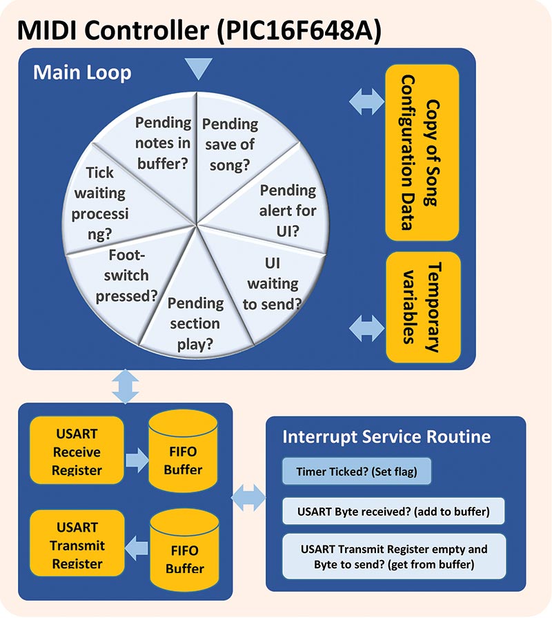
■ FIGURE 11. The MIDI controller chip — very busy PIC!
The USART (Universal Asynchronous Receiver-Transmitter) receives and transmits MIDI data via FIFO (First in First Out) buffers in internal RAM. The ISR (Interrupt Service Routine) handles the reading and writing to the buffers. Separate to this is the main program loop that runs a variety of tasks.
The thing that matters above all else in our system is that we must never ever lose any received data. The PIC16F648A has a one byte receive register in the USART that receives the MIDI data. As soon as this is filled, the byte must be transferred to the receive buffer in RAM. Otherwise, it will be overwritten.
Another essential is that any note messages are handled accurately and promptly. If they are being recorded, then they must be time-stamped ideally within 10 milliseconds of the ‘real’ time to maintain accuracy. If they are output (either echoed from the input or played back from recorded data), this must be fast to avoid noticeable delay. Technically speaking, there’s a need for low jitter and low latency.
All code has been carefully crafted and all unnecessary steps eliminated while keeping overall functionality. The ‘Pro’ (paid monthly) version of compiler-optimization is used in MPLAB to ensure maximum speed (and minimum code size). Tricks such as bit-shifting instead of slower multiply have been used. The PIC16F648A is driven at its maximum operating frequency of 20 MHz.
It was decided to write all software in fully-optimized C without any handwritten assembler. This was purely a practical decision, realizing that highly optimized code can still be extremely fast and much easier to write.
The MIDI protocol has a trick up its sleeve called running status that lets you only send a status byte when the status changes from the previous message. This means that, for example, you can send a string of ‘note on’ messages but only send one status message to indicate they are of type ‘note on.’ Running status can reduce note data by a third, so is fully utilized in this design.
The MIDI controller PIC not only processes MIDI messages, but also applies the logic of transposing, tempo management, and playable ranges. It adjusts recorded tempo using a timer1 pre-scalar lookup, plus it communicates data with SRAM and interfaces to the other microcontrollers! Because this chip is so busy and everything is time-critical, it must be the master.
Imagine being in a crowded restaurant with friends and placing an order for drinks. The waiter leaves, then later returns weaving between tables, holding the drinks on a tray above his head. It makes sense that he is in control, not you — even though you’re the customer. He judges the time-critical swerves and swoops to make it safely back to your table.
The UI controller PIC must request to send a message to the MIDI controller PIC, which when ready acknowledges with a handshake. The MIDI controller PIC controls the clock signal that ‘pulls’ in the message and will possibly interrupt reception to do other time-critical tasks.
Round-robin Scheduling with Interrupts
The type of scheduling used to manage tasks in the MIDI controller PIC is called round-robin with interrupts. This is a scheme that balances the need for simplicity against the demands of 'immediate' real time processing.
The main loop shown in Figure 11 can be thought of as a spinning wheel, where each task on the wheel is traversed in series (round-robin).
The ISR handles received and transmitted bytes, routing them to and from associated buffers. The tasks are simple and so critical that they are handled immediately in the ISR.
The ISR also sets a flag when the timer ‘ticks,’ plus sets the song position variable. However, the actual processing of the tick occurs in the round-robin loop.
Task Scheduling Strategies
In real time computing systems where a lot of tasks need to be performed, task scheduling is important. This is a complex subject with many variants. The simplest is what’s called round-robin where there’s a loop and each task in the loop is run one after the other; the loop then repeats over and over. At the other extreme is a real time operating system with complex features and operation aiming for the minimal possible delay in execution.
The middle ground contains a round-robin with interrupts. Interrupt routines deal with the very urgent needs of the hardware and then set flags. The main loop polls the flags and does any follow-up processing required by the interrupts.
An example might be incoming UART data that if left too long could be overwritten by the next incoming data byte. The time-critical task of retrieving the data is handled as soon as the interrupt fires by moving the data byte into a circular buffer. However, processing the data byte is usually what’s called a ‘soft’ real time requirement and can be handled later by the main loop when it gets around to it.
Although it’s useful to think of a robin hopping round each task, Wiki tells us that the term actually dates from the 17th century French ‘ruban rond’ (round ribbon), describing the practice of signatories to petitions against authority (usually government officials petitioning the Crown), appending their names on a document in a non-hierarchical circle or ribbon pattern.
Beware the Buffer
Buffers are admittedly essential in many systems to smooth demand peaks, but need to be used with caution in real time systems.
They smack of procrastination: Doing things when it suits you and alleviating the immediate stress. However, this doesn’t help when there’s a tight schedule!
Also, putting things off can just postpone throughput issues. If the rate of emptying water from a leaking boat is less than the rate of water being taken on board, then the boat will eventually sink!
The height of the boat is like the buffer size. In real time systems, we must design for a shallow boat to ensure tasks are completed promptly and must ensure we empty water from the boat quickly! It’s easy to think all we need to do is slap in big buffers to overcome real time issues.
Spreading the Load with Parallel Processing — Working as a Team
The MIDI controller PCB also has true parallel processing to improve throughput. Figure 12 gives an example of what each processor is doing at a snapshot in time; the MIDI controller is midway through processing a received note. At the same time, the foot-switch controller is listening for a foot-switch press; the metronome controller is listening for a ‘beat’ command; and finally, the UI controller is busy updating the display.
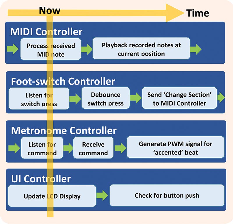
■ FIGURE 12. Spreading the load with parallel processing.
Parallel processing needs efficient inter-processor communication. This system uses three protocols (shown in Figure 13), each one carefully designed for their unique purpose.
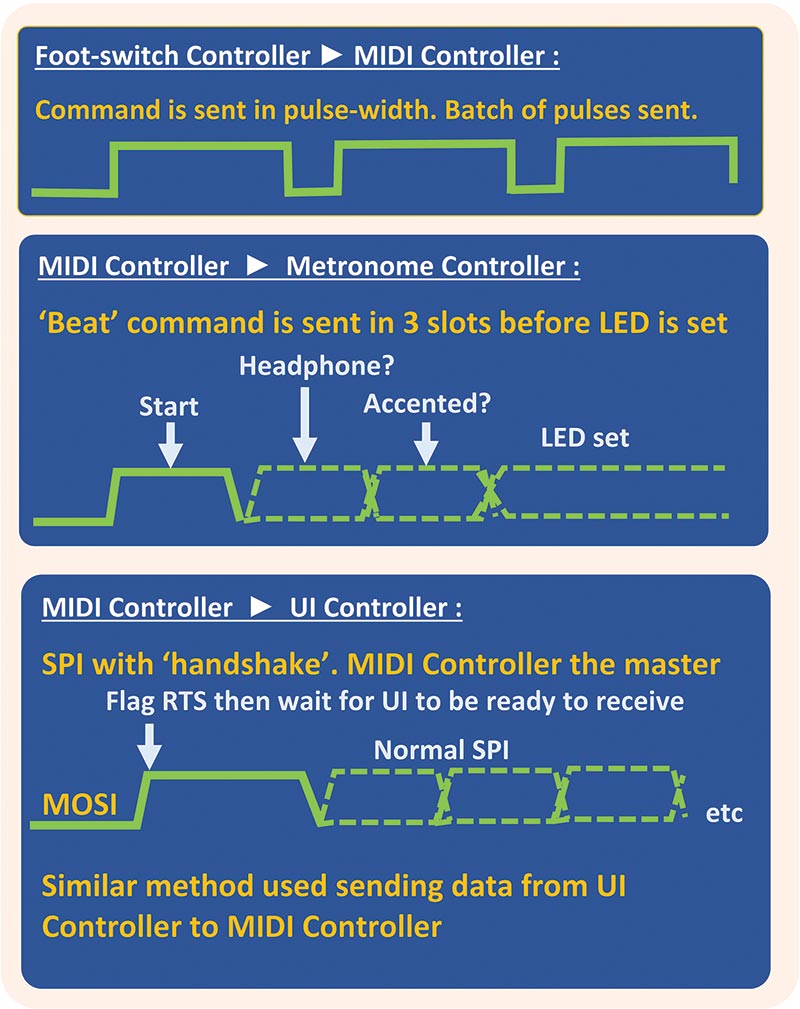
■ FIGURE 13. Three different command ‘languages.’
The foot-switch controller sends commands to the MIDI controller via a burst of pulses, with the pulse width representing the command. This is a single-pin solution without any handshaking. The presence of a pulse is polled by the MIDI controller. A batch of pulses is sent in sufficient number to ensure the MIDI controller always receives the command.
After reception, the MIDI controller doesn’t listen again for a while. This system works well for foot-switch presses because they are relatively infrequent.
The MIDI controller sends beat messages to the metronome controller. Because of pin shortages on the PIC16F648A, we cheekily piggy-back an LED pin. Because the ‘play’ LED is synchronized with the beat, we send a very short three-time-slot burst of signal at every beat transition. This signal is invisible to the eye.
Lastly, the MIDI UI controllers communicate using standard SPI (bit-banged) that has an additional initial handshake. Before comms start, the sending device flags that it wants to send, then waits for a handshake. The MIDI controller is always the SPI master.
SRAM and Dynamic Memory Allocation — The Memory Game
A movie theater can’t just allocate seats sequentially. If people cancel their bookings, the ‘holes’ must be filled if possible. The same goes for our SRAM data. We need what’s called Dynamic Memory Allocation (DMA).
Figure 14 gives an overview of how SRAM is used. If all we ever wanted to do is add data, then all would be easy. However, the reality is that we can delete songs plus change track recordings. DMA allocates memory to requesting processes and tries to re-use ‘holes,’ thereby making best use of limited memory resources.

■ FIGURE 14. The SRAM memory layout and Dynamic Memory Allocation.
There are many DMA methods. This design uses a simple fixed-block memory pool approach. Recorded note data is divided into blocks of 256 bytes in SRAM. Each block has a header byte to indicate: if the block is empty; if it’s the last block in a sequence; or the address of the next block in the sequence. Note events are stored sequentially inside a block.
This method is perfect for sequentially recorded MIDI events, but we must choose the block size carefully. Ideally, it’s a size that allows bit-shifting to calculate addresses (being faster); is big enough to ensure time spent processing block-headers is insignificant; and is small enough to minimize internal fragmentation.
Internal fragmentation is when a block is only partially used, and the unused bytes of the block are inaccessible and wasted. This isn’t ideal but is unavoidable. Reducing the block size reduces this wastage but increases the effect of block overheads.
The 23LCV512 SRAM chip can store 2,000+ note events. The capacity doesn’t equate to duration, in contrast to recording audio.
The 23LCV1024 is the 23LCV512’s big brother with double the memory. So, why don’t we use this instead? The answer is because of addressing and access times. The 23LCV1024 has 24 bits addressing whereas the 23LCV512 has 16 bits. The more memory, the longer the path to the data. Since memory is accessed, often in our solution we want to reduce access time. We compromise between memory size and speed.
Also, we use a simple algorithm to locate a free memory block. It scans all blocks until a free one is found. The more memory, the slower this process can be.
Track Pointers — Keep Things on Track
As this is a recording and playback system, we must know the current position for each track. Figure 15 shows how we make use of track pointers.
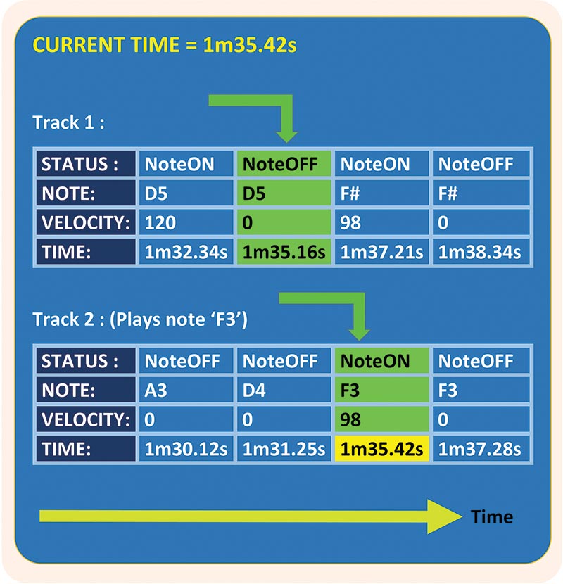
■ FIGURE 15. Track pointers for the current position.
When recording a song section, we can record up to four tracks simultaneously. Note data for each track is sequentially written to SRAM inside linked memory blocks. The actual amount of data stored for each track can be vastly different.
To find the current position of each track, we must scan the track events, comparing the event time-stamps to the overall song position. Pointers refer to the located positions.
The PIC16F883 User Interface Controller — the Second Fiddle

■ UI controller schematic.
This chip is on the UI controller PCB shown in Figure 16 and is the slave to the MIDI controller PIC; its tasks are less time critical. However, it still has much to do, managing user navigation and input, updating the LCD display, and setting LEDs. It uses a powerful menu-navigation technique to cram as much as possible onto the chip.
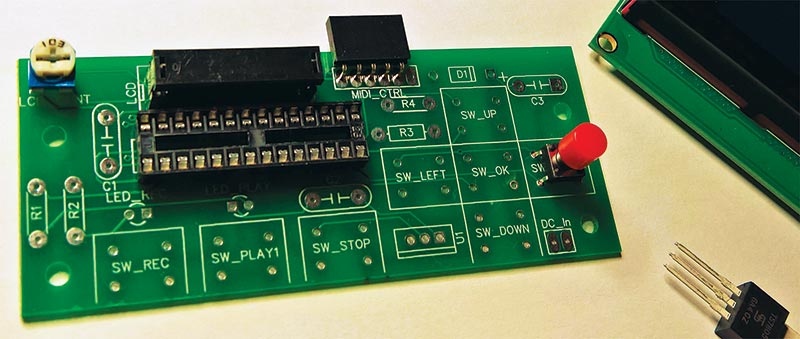
■ FIGURE 16. The UI controller PCB.
Many of the tasks are relatively simple in comparison to the complexity of the MIDI controller. The most difficult challenge is designing a menu system where values can be navigated and edited. The approach taken here uses a Value Navigation Table.
Figure 17 shows part of the display. The characters on the display are either background or part of value blocks. The background characters are held in EEPROM and are used as the basis of the display. The value blocks contain overlaid values.
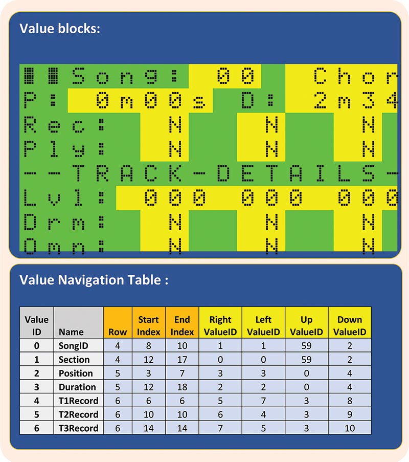
■ FIGURE 17. The user interface system.
Values are held in a data structure as integers. The Value Navigation Table contains information about the location and size of each value block, and the navigation between blocks.
Much code is written to translate raw integer values into different displayed types (whole number, percentage, time, note name, on/off blob, etc.). Values are edited using increment and decrement buttons, with the step size depending on the duration of the button press.
Figure 18 shows song 1 with the verse selected. The position is 0 seconds, the duration is 29.7 seconds, and track 2 is enabled for playback.
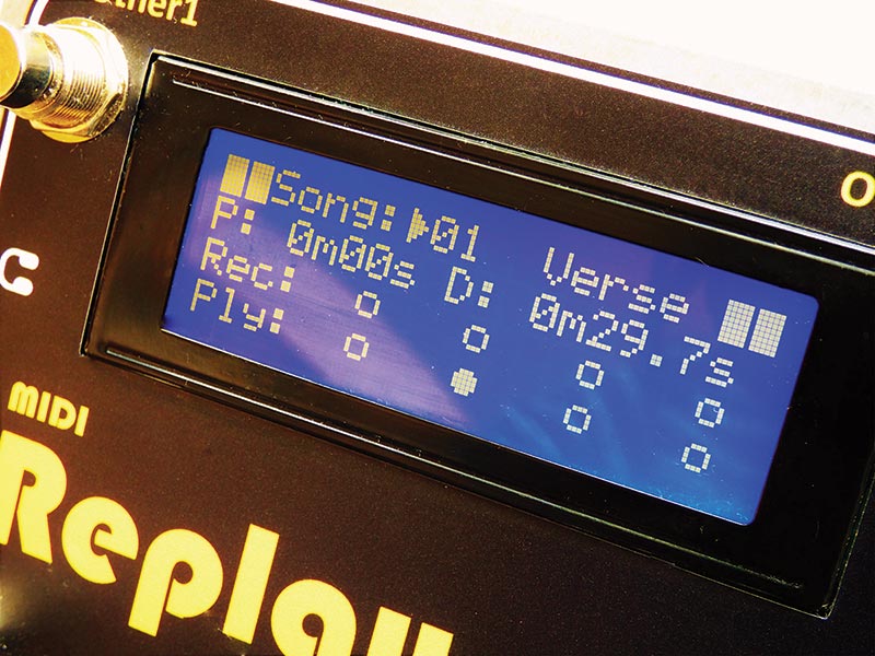
■ FIGURE 18. A close-up in Edit mode.
In Performance mode, the LCD digit size is made large by using custom characters and a ROM-based character map.
UI Controller Parts List
| Item |
Name |
Value |
Notes |
| C1, C2 |
Capacitor |
100 nF |
|
| C3 |
Capacitor-Polarized |
100 µF |
|
| D1 |
Diode |
1N4001 |
|
| LCD Display Module |
20x4 Alphanumeric LCD Display HD44780 |
|
There are many modules out there based on the HD44780 controller. Dimensions are important if using suggested Hammond enclosure. Module used is roughly 98 x 60 mm. Note that the design drives the display in parallel mode. |
| LCD |
IDC Connector to connect to LCD module |
IDC2X8M. 1565524 Multicomp Connector, PCB, Transition, IDC, 16-way |
|
| LCD_CONT |
Trimmer Pot for LCD Contrast. 6 mm Cermet Horizontal Variable Trimmer Potentiometer |
10K |
|
| LED_PLAY |
LED-3R_Green |
3 mm Round |
|
| LED_REC |
LED-3R_Red |
3 mm Round |
|
| MIDI_CTRL |
Header 6-pin |
|
|
| R1, R2 |
Resistor |
2K2 |
|
| R3 |
Resistor |
10K |
|
| R4 |
Resistor |
560 |
|
| SW_DOWN |
Tactile Switch |
6x6 mm Tactile Switch - Button Height 6 mm |
|
| SW_LEFT |
Tactile Switch |
6x6 mm Tactile Switch - Button Height 6 mm |
|
| SW_OK |
Tactile Switch |
6x6 mm Tactile Switch - Button Height 6 mm |
|
| SW_PLAY1 |
Tactile Switch |
6x6 mm Tactile Switch - Button Height 6 mm |
|
| SW_REC |
Tactile Switch |
6x6 mm Tactile Switch - Button Height 6 mm |
|
| SW_RIGHT |
Tactile Switch |
6x6 mm Tactile Switch - Button Height 6 mm |
|
| SW_STOP |
Tactile Switch |
6x6 mm Tactile Switch - Button Height 6 mm |
|
| SW_UP |
Tactile Switch |
6x6 mm Tactile Switch - Button Height 6 mm |
|
| U1 |
5V Power regulator IC |
7805 |
|
| UI_CONTROLLER |
UI Controller, Microcontroller |
PIC16F883_SP |
Recommend an associated DIL socket so that this chip can be reprogrammed if necessary. |
| Cable |
Ribbon cable 16-way (or more). Just tear off length as required. |
|
|
| Button Caps (Optional) |
Round Tactile Button Caps for 6 x 6 x 9.5 mm |
|
|
| 4 x PCB Spacers (Optional) |
PCB Round Spacer |
Outer Diameter: 6.3 mm; Inner Diameter: 4.2m; Overall Length: 10 mm |
Dimensions are just suggested and are not critical. Just need to ensure all components are held clear of metal enclosure! |
| Power Socket (Optional) |
Power Socket for the Enclosure |
Panel/Chassis Mount Connector with nut 5.55 mm bore 2.1 mm pin |
|
Seamless Transitions — The Smooth Operator
Foot-switch presses don’t change a song section immediately. Rather, they tell the Box that after the current section is finished playing, the clicked section is the next section to play. It’s more like a pending section change. As long as you have set the track durations accurately, this will result in beautifully smooth transitions between sections.
The sections are either looped or normal (not looped). When a looped section ends, it will either loop again, or if there is a pending section change, playback will hop to the new section. Normal sections will either stop when the end is reached or hop to a pending section change.
This makes operating the Box in Performance mode extremely simple. The only thing to worry about is telling the Box which section to go to next. You can tell it at any convenient point during the currently playing section.
How It Performs — The Grand Finale!
After considerable design and build effort, the result is a system that performs excellently! However, ‘excellent’ needs some quantifying.
In chaotic real time systems, it’s often best to use statistical Response-Time Analysis (RTA), which highlights probable performance rather than absolute performance.
Figure 19 shows a test measuring response to a spike load on the system. A batch of 18 note events is sent to the Box at the same time (simulated by a sequencer). In practice, this is very unlikely to happen and even a few milliseconds difference in ‘note on’ reception would alleviate the load on the microcontroller.
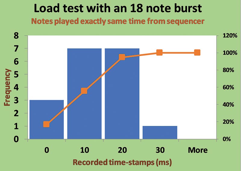
■ FIGURE 19. Load testing.
The histogram shows how the recorded notes are time-stamped. As we can see, virtually all are processed and stamped after 30 milliseconds, and over half within 10 milliseconds. This is good considering we are unlikely to ever notice a 10 millisecond delay!
Figure 20 shows a test measuring ‘Jitter’ when the system is under moderate load. A stream of ‘note on’ messages spaced 34 milliseconds apart is blasted at the Box.
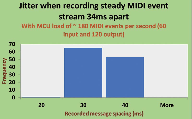
■ FIGURE 20. Measuring jitter.
The Box echoes this stream to its output on two channels — the overall load being in the order of 180 MIDI events per second. The recorded message spacing should be 30 milliseconds (the Box has a timing precision of 10 milliseconds). As we can see from the histogram, most are indeed recorded at this interval. However, almost half are recorded at 40 milliseconds. Considering this represents quite a hefty unrealistic load, even this result shows the system response is fully acceptable!
The Desktop App — Load and Go!
Figure 21 shows a screenshot of the MIDI Replay app for Windows™ that accompanies the Box.
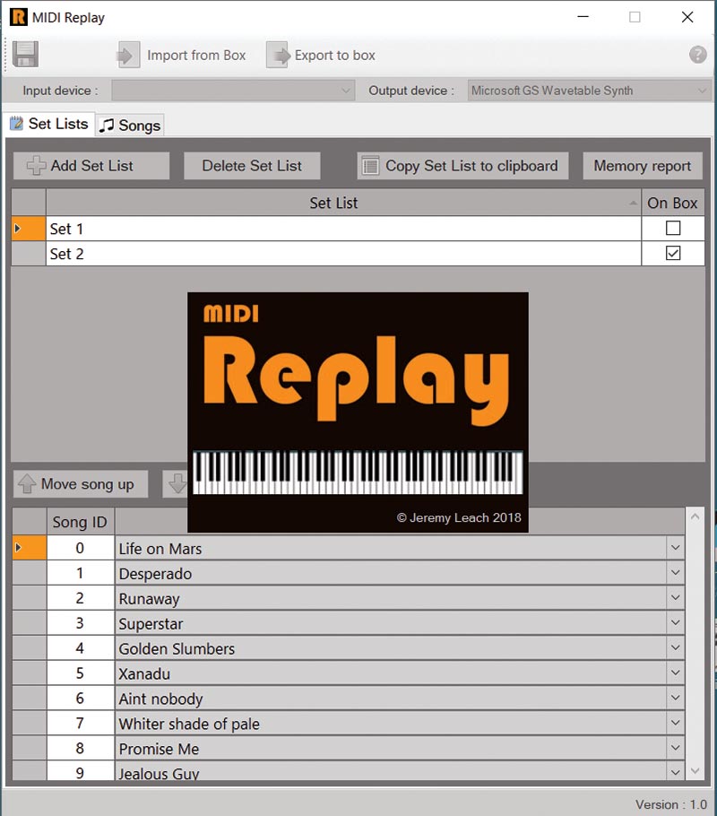
■ FIGURE 21. MIDI Replay desktop app.
The app is a fundamental part of the whole system, and acts as the bridge between the box and high-level song management and editing capabilities.
The app can be downloaded from https://collectany.blob.core.windows.net/midireplay/setup.exe.
Clicking this link downloads the setup.exe which you then run. Select ‘run anyway’ when the Windows protection screen is displayed (Microsoft recognizes this app as from an unknown publisher). You will automatically get updates to this app if any are made.
Song settings and recorded tracks are communicated to the app via MIDI ‘Sys-Ex’ data messages. Recordings are saved to standard MIDI files that can be edited by any Sequencer app.
The app lets you define songs and put songs into sets that can be synced with the Box. The keyboard player can load up a set before a performance and simply click and go at the gig!
The software is written in .NET and C# as a ‘WinForms’ application. The full solution and associated files are included with the article downloads.
Time to stomp on! NV
Resources
History of multi-track recording
https://en.wikipedia.org/wiki/History_of_multitrack_recording
Bruce Springsteen’s Nebraska albums made on a four-track Portastudio
https://tascam.com/us/support/news/481
Wiki’s comprehensive summary of MIDI
https://en.wikipedia.org/wiki/MIDI
SparkFun’s very readable summary of MIDI
https://learn.sparkfun.com/tutorials/midi-tutorial/all
Harmony Central’s fascinating history of MIDI
www.harmonycentral.com/articles/a-brief-history-of-midi
The MIDI Association’s summary of MIDI messages
https://www.midi.org/specifications-old/item/table-1-summary-of-midi-message
A review and overview of embedded scheduling techniques
https://www.embeddedrelated.com/showarticle/969.php
A general overview of memory management
https://en.wikipedia.org/wiki/Memory_management
A nice explanation of interfaces and ‘encapsulation’ that can be an analogy of MIDI talking to all sorts of devices
www.eeng.dcu.ie/~ee553/ee402notes/html/ch01s04.html
Kaiser Chiefs MIDI Tech tells of ‘MIDI Madness’ during live performance (at end of article)
https://www.soundonsound.com/people/roger-lyons-kaiser-chiefs-midi-tech
Hitachi HD44780 LCD controller
https://en.wikipedia.org/wiki/Hitachi_HD44780_LCD_controller
Parallel and distributed computing
https://en.wikipedia.org/wiki/Distributed_computing#Parallel_and_distributed_computing
A Statistical Response-Time Analysis of Real Time Embedded Systems
https://ieeexplore.ieee.org/document/6424817
Downloads
What’s in the zip?
Source Code
Datasheets
Schematics
Gerber Files
MP3 File