Editor's Note - This article specifies an IC that has become obsolete since it was originaly published. You MAY find a different source that has it in stock OR be able to build it using a substitute part, if you so desire. We felt that this discussion of voltage references was still of value, so please keep that in mind as you read.
Okay, you’ve wired up the latest whiz-bang sensor to your processor-controlled project. The sensor has been connected to the 12-bit A/D and now the moment of truth. You apply power and look at the data ... Hmmmm, the numbers don’t look quite right. After much head scratching, you measure the A/D voltage reference with your trusty DMM and get to thinking. A 12-bit A/D means the input signal is going to be represented by one of 4,096 possible codes; one part in 4,096 is approximately .024%. In other words, if you want to get 12 bits of absolute accuracy, the reference voltage must be within .024% of the desired value. This puts a heavy burden on the test equipment used to measure the reference voltage.
So, just how accurate is your DMM?
If you had a separate accurate voltage reference available, you could determine if your DMM is “telling the truth.” This is but one example of why you might want an accurate voltage reference. Other possible reasons include using one to calibrate your DMM, or to construct a precision voltage-to-frequency converter or current source.
The applications for a precision reference fall into two general categories: instrument (DMM, DVM) calibration/accuracy verification, or as a circuit component, such as the reference for an A/D converter.
The construction part of this article is geared towards voltmeter calibration and/or accuracy verification. However, the following discussion of various reference voltage parameters applies equally well to using a voltage reference as a circuit element.
I’ll quickly go through several voltage reference options, starting with inexpensive and fairly crude devices and progress up to a precision lab-quality circuit.
Zener Diodes
On the low end of the reference accuracy continuum, we have the lowly zener diode. It is readily available and 5% accurate devices are inexpensive. A 5.1V, 1N751A zener can be purchased for about a dime and is a good starting point for our discussion.
Zeners provide their stated breakdown voltage only with a particular test current, Iz, flowing through them. This means that the series-limiting resistor shown in Figure 1 must be sized to guarantee that this current will, indeed, flow.
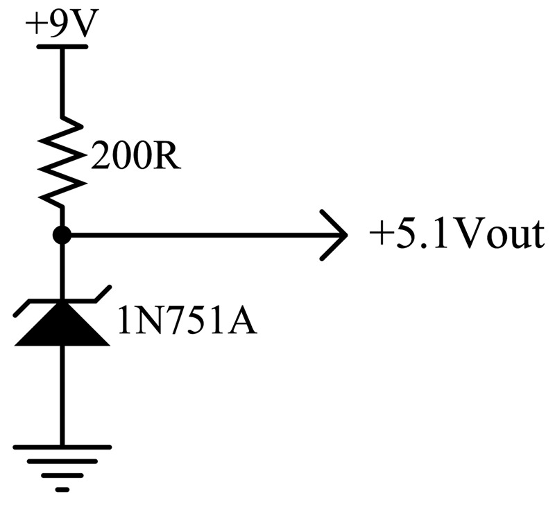
FIGURE 1. Inexpensive, 5% accurate, 5.1V reference.
For instance, with a 9V supply and a 1N751A which has a Iz of 20 mA, the resistor value is (9-5.1)/20 mA = 195 ohms. Note that the value of R1 will be different if anything other than a high impedance is placed across the zener.
I don’t want to dwell too much on the lowly zener but there is one point worth emphasizing. You may be asking, what is the advantage of using a zener if an accurate supply voltage and a precision resistor are needed to get the precise desired current flowing through the device? Well, fortunately, things are not as critical as they might first appear. The reverse impedance of the zener is quite low, which means that the current can vary quite a bit and the voltage will still remain relatively constant. As part of the research for this article, I tested five 1N751A zeners from Fairchild Semiconductor. I used a 200 ohm, 5% series resistor whose measured value was 197 ohms. When I varied the supply from 8V to 10V, the current through the least accurate zener of the group varied from approximately 14.3 mA to 24.3 mA, but the zener voltage stayed within 2.3% of 5.1V. The best of the five devices was within 0.2% of 5.1V! Not bad for such a simple and inexpensive component. Your mileage may vary.
Three-terminal Regulators
Next up, we have the common 7805 three-terminal regulator. The MC7805 from Fairchild (and others) costs about $.50, gives 4% accuracy under light load, is short-circuit proof, and can more easily accommodate wide swings in load current than the simple zener regulator. Higher accuracy devices are available such as the 2% KA7805AE for $.80. Figure 2 shows a typical application circuit.
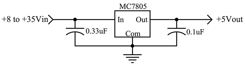
FIGURE 2. 4% accurate, short-circuit proof, 5V reference.
For 1% accuracy, you might want to consider the LM4040DIZ-5.0 from National Semiconductor. This device costs about a dollar and is a “shunt” reference similar in general concept to a zener except that it isn’t nearly as picky as to the current flowing through it. With a 1% accurate device at room temperature, the output voltage is 5.00V plus or minus 50 mV. If the current through the device varies from 1 mA to 15 mA, the voltage drop is guaranteed to change a maximum of an additional 10 mV. Figure 3 shows a typical circuit.
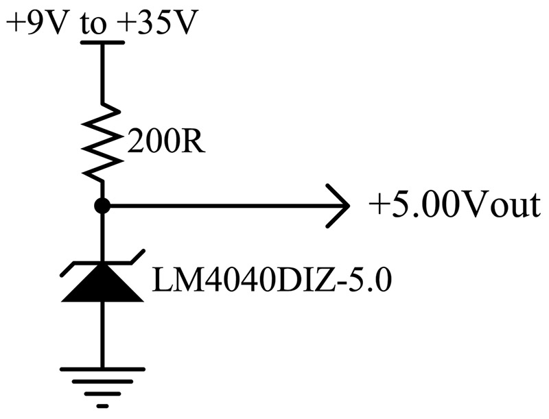
FIGURE 3. 1% accurate, 5V reference.
So far, accuracy has been stated as a percentage of the nominal voltage with no additional qualifying conditions. One such condition is temperature. Unfortunately, changes in ambient temperature will cause a change in the reference voltage, regardless if the device is a zener or a precision reference.
For instance, the LM4040 DIZ-5.0 has a worst-case temperature coefficient of 150 ppm/°C. This means that for every degree up (or down) from 25°C, the breakdown voltage of the device will change by 150/1,000,000 or .015%. Obviously the smaller the temperature coefficient, the better.
For general indoors lab work, the temperature coefficient will probably not be as important as it would be if the voltage reference were exposed to more extreme temperatures. Your specific application will determine if you need to use a device with a low temperature coefficient. As you might suspect, devices with a low temperature coefficient tend to cost more than those with a higher temperature coefficient.
Going Up the Accuracy Food Chain
Next up on the accuracy scale, you could try a LM4040AIZ-5.0; this device is accurate to 0.1% and has a moderate temperature coefficient of 100 ppm/°C. Now we are getting somewhere! But, as usual, you get what you pay for. This increased performance will approximately double the cost to a little over $2.
Next, we can consider the Analog Devices AD586L shown in Figure 4.
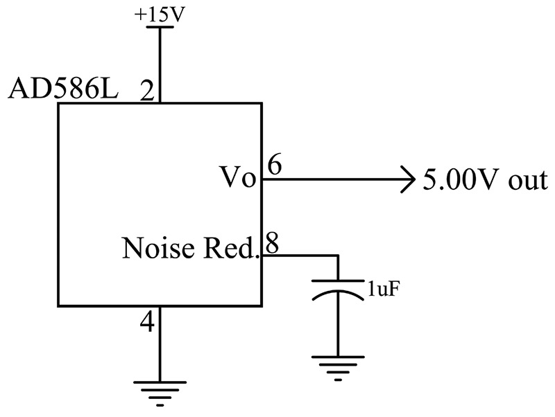
FIGURE 4. .05% accurate, 5 ppm, 5V reference.
This device provides 5.000V within 2.5 mV (.05% accuracy) and has a low temperature coefficient of 5 ppm/°C, an aging rate of 15 ppm/1,000 hours, and a supply current of 3 mA. It will cost you a little over $9, however.
At this point, I need to explain a little about aging rate — also known as long-term stability — specifies how the reference voltage will change over an extended period of time. In other words, even though the temperature, applied voltage, and load current may be constant, all voltage references will slowly drift over time. A 15 ppm/1,000/hour aging rate means that after 1,000 hours (about 42 days), the voltage can be expected to be 15/1,000,000 or .0015% higher or lower than its original value.
Now for the pièce de résistance! Intersil has recently come out with a series of voltage references that significantly improve upon the historical price/performance ratio. The series includes devices with 1.024V to 5V reference voltages with high accuracy, low temperature coefficient, low aging, and very low current consumption. The X60008C is used in the construction part of this article and costs about $7.50, provides 5.000V accurate to within 500 µV (.01%) , has a low temperature coefficient of 5 ppm/°C, low aging rate of 10 ppm/1,000 hours, and incredibly low supply current requirement of 800 nA. Figure 5 shows a schematic using this device.
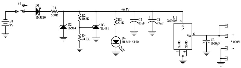
FIGURE 5. Schematic of the battery-powered, .01% accurate, 5.000V reference.
Circuit Description
The 5V precision reference is powered by a 9V battery. The circuit draws about 4 mA with a fresh battery, which results in a battery life in excess of 48 hours of continuous operation. Increased battery run-time can be achieved by applying power, letting the unit stabilize, making your measurement, and then turning the power off. D4, a TL431 “variable zener” whose breakdown voltage is set by R2 and R4, produces 6.5V to supply power to the X60008.
The .01% accuracy of the X60008 is specified with a supply voltage of exactly 6.5V; the 5.000V reference output can deviate as much as 100 µV per volt away from 6.5V. For example, if the supply is 7.5V, the 5.000V reference could be off as much as 600 µV(500 µV from the initial .01% tolerance plus another 100 µV from the supply being 1V from the ideal 6.5V); 1% resistors and a 0.5% TL431 are used to keep the 6.5V supply between 6.3V and 6.7V.
Diodes D1 and D2 prevent damage to the circuitry if the battery is installed backwards. A low current LED, D3, is used as a visual power-on reminder. I designed the circuit to function correctly with a battery voltage as low as 8.0V. However, I was pleasantly surprised when I measured the first couple of prototypes and found that the 5V reference voltage was within .01% with a battery voltage all the way down to 6.7V! Hopefully, you will get equally good results.
Besides supply voltage and component tolerances, there are two more potential error sources that need to be mentioned. Mechanical stress on the die inside the X60008 package can cause a voltage shift in the reference voltage. For instance, pressing down on the board and causing it to flex can cause stress. Looking at the photo in Figure 6, you will see two slits in the printed circuit board (PCB) on either side of the X60008. The purpose of these slits is to de-couple the X60008 from the rest of the board and make it more difficult for mechanical stresses to be transmitted to the reference.
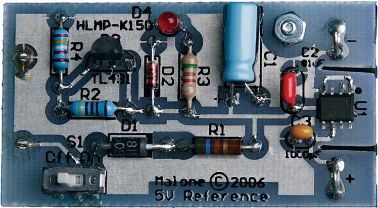
FIGURE 6. Photo of the completed reference. Note PCB slits adjacent to X60008.
Another potential error source is temperature stress. When soldering the leads of the X60008 to the circuit board, work quickly! It is stressful to the IC die to have one lead at an elevated temperature and other leads at a lower temperature. Leaving the soldering iron on a pad too long can result in the reference voltage permanently shifting to an out-of-spec value. If you have an adjustable temperature soldering iron, don’t turn it up beyond 600°F. Use of a flux pen can be very helpful.
The X60008 package has eight leads, but only four are used. I purposely left off the four PCB pads associated with the unused IC leads; this minimizes the number of leads that need to be soldered, which lowers the amount of thermal stress that the die is exposed to. If you aren’t confident in your soldering ability, you may want to have someone help you who is more skilled.
PARTS LIST
| Item |
Description |
Supplier/Part No. |
| B1 |
9V alkaline battery |
Duracell/MN1604 |
| B1 |
Battery holder |
Mouser/12BH611 |
| C1 |
4.7 µF 16V electrolytic capacitor |
Mouser/140-XRL16V4.7-RC |
| C2 |
0.01 µF ceramic capacitor |
Mouser/581-SR215C103KAR |
| C3 |
1,000 pF ceramic capacitor |
Mouser/80-C315C102K5R5TA |
| D1 |
1N5819 Shottky diode |
Mouser/625-1N5819-E3 |
| D2 |
1N914 signal diode |
Mouser/78-1N914 |
| D3 |
LM431CCZX variable zener |
Mouser/512-LM431CCZX |
| D4 |
HLMP-K150 low current LED |
Mouser/638-HLMPK150 |
| R1 |
560 ohm 5% 1/4W resistor |
Mouser/291-560-RC |
| R2 |
40.2K 1% 1/4W resistor |
Mouser/271-40.2K-RC |
| R3 |
5.1K 5% 1/4W resistor |
Mouser/291-5.1K-RC |
| R4 |
24.9K 1% 1/4W resistor |
Mouser/271-24.9K-RC |
| S1 |
Slide switch |
Mouser/688-SSSS22700 |
| U1 |
X60008CIS8-50 |
Digi-Key/X60008CIS8-50 |
| 1 ea |
2-56 x 3/8” screw |
Digi-Key/H130-ND |
| 1 ea |
2-56 nut |
Digi-Key/H212-ND |
| 1 |
Printed circuit board |
|
Assembly
To help keep the cost down, I decided on designing a single-layer PCB. Since the actual voltage reference IC is surface mount, this pretty much dictated that everything be soldered on the component side of the board. This is a little unconventional but no big deal, and as can be seen in Figure 7, results in a compact assembly. The PCB sits on top of the plastic 9V battery holder and is supported by small bosses on the holder that act as PCB standoffs. After component leads are inserted through the board and soldered, cut off the excess lead length flush with the bottom of the board.
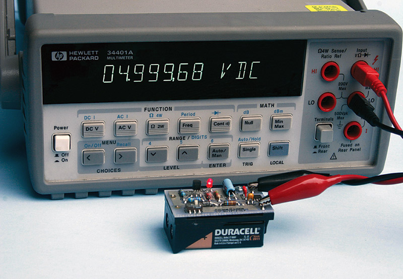
FIGURE 7. This photo shows the 9V battery and holder supporting the PCB.
Normal anti-static precautions need to be taken during assembly (anti-static work surface and wrist strap). Use a small tip on your iron and solder the X60008. As mentioned above, don’t apply more heat or time than is necessary to achieve a reliable connection. Place and solder the remaining components, saving the battery holder for last. Orient the LED properly by noting that the cathode lead is shorter than the anode and is inserted into the square pad on the PCB. To provide access for your soldering iron tip, space D3, D4, C2, and C3 up off the board a bit. Take a couple of cut-off resistor leads and form them into a “U” shape and insert them into the + and – 5V reference output pads.
After all the components are in place and their leads cut off flush with the bottom of the board, insert the two leads of the battery holder through the holes in the PCB. Next, use a 2-56 x 1/4” screw and nut to hold the PCB firmly against the battery holder. Finally, solder the battery holder wires to the PCB.
Test
Slide the power switch to the OFF position. Insert a fresh 9V alkaline battery into the holder and slide the switch to the ON position. The LED should light up; if not, look for proper polarity of all the diodes including the LED. Using your DMM, measure from the — output terminal to the cathode of D2. This voltage should be between 6.25V and 6.7V. Finally, put your meter across the + and – output terminals and you should see 5.000V displayed.
For highest accuracy, there are three things to keep in mind. First, the voltage reference should be used at temperatures as close to 25°C (77°F) as possible. A few degrees either way won’t make much difference, but you wouldn’t want to put the unit out in the sun and expect to get .01% accuracy. Secondly, allow the circuit to temperature stabilize for 30 minutes with power applied before use. Lastly, the X60008 can source and sink up to 10 mA, but for highest accuracy it should only be connected to a high impedance load such as a voltmeter.
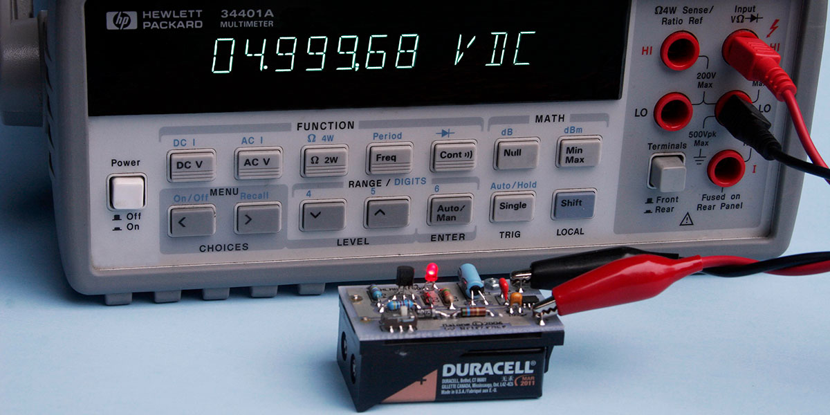
If higher current is needed, a buffer amplifier should be constructed; check the Intersil website (www.intersil.com) for sample circuits. Figure 7 shows a completed prototype with the reference voltage displayed on a recently calibrated, .003% accurate, 6.5 digit, Hewlett Packard 34401A DMM.
Parting Thoughts
The previous brief survey of voltage references mentions only a small fraction of the devices that are available. For additional products, check the web pages of Analog Devices, Intersil, Linear Technology, Maxim Integrated Products, National Semiconductor, On Semiconductor, Texas Instruments, and Zetex. These manufacturers also have application notes available that delve into the details of voltage references and will help insure that you have the knowledge to apply them properly. NV
NOTE: PCB patterns and artwork are available below in the downloads.
Downloads
What’s in the zip?
PCB pattern and layout.