Wouldn’t it be great to detect a flooding issue before it’s too late? Well, this device can detect when rising water occurs. The circuit shown in Figure 1 is a schematic for a flood detection alarm.
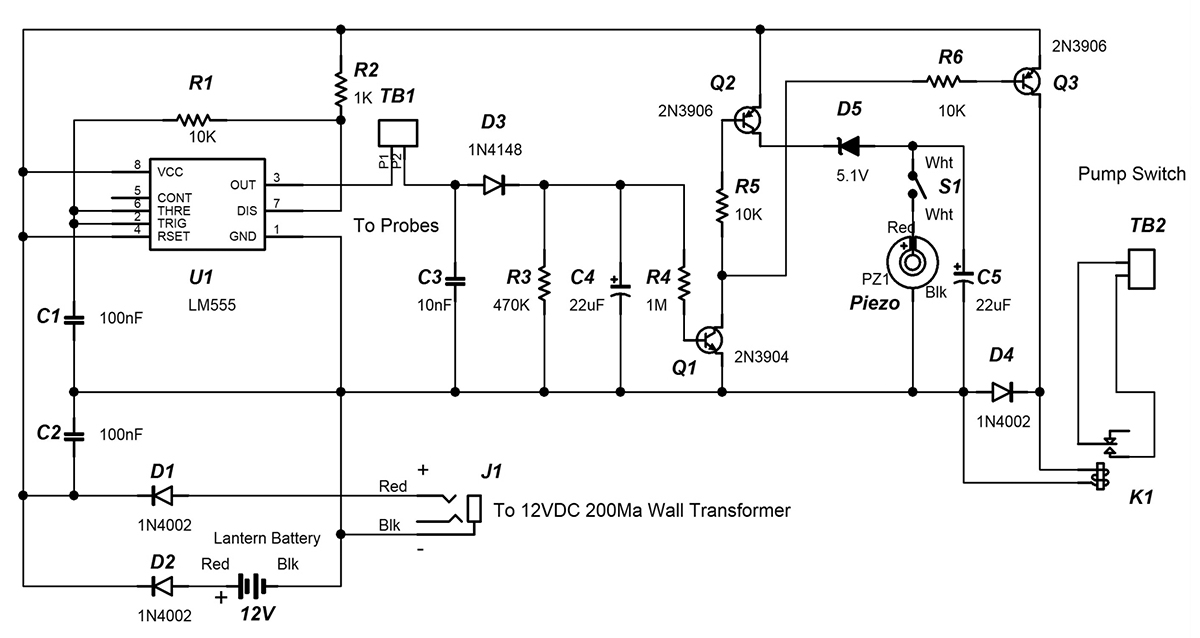 |
| FIGURE 1. |
This project consists of a box containing circuitry and the water probe assembly. When water touches the probe assembly, an alarm will sound. A relay is provided to switch on a water pump. As long as the probe assembly is in contact with the water, the pump switch will remain on. The alarm can be shut off with a switch once the flooding has been detected. Optionally, a 12V lantern battery can be used as a back-up power source if the power from the wall transformer is interrupted.
Circuit Description
The circuit in Figure 1 consists of a 700 Hz oscillator, rectifier, threshold detector transistors, and drive transistors. U1, R1, R2, and C1 form the 700 Hz oscillator. This drives probe P1 on TB1. When water touches probe P1 and P2, P2 picks up the square wave. The signal at P2 is rectified by D1 and charges C4. Q1 is used as a threshold detector. If the charge on C4 reaches a threshold of approximately 600 mV, Q1 turns on. When Q1 is on, driver transistors Q2 and Q3 are also on.
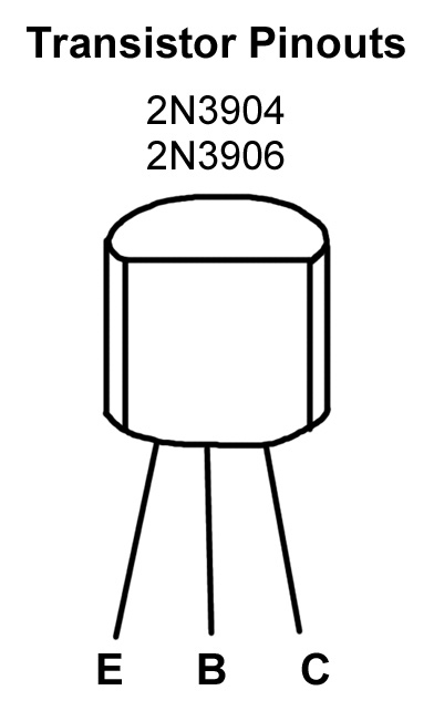 |
| FIGURE 2 |
Q2 drives the piezo alarm and Q3 energizes the pump switch relay coil. D4 is used to eliminate the back-EMF when the relay coil voltage is turned off. C4 remains charged when the probes detect water. If the water level falls below the probe tips, C3 discharges through R3, providing a time delay in turning off Q1. This means that the relay will not chatter when the probes are just barely in contact with water.
The unit is powered by a 12 VDC 200 mA wall transformer. However, the device can operate from a lantern battery as a backup power source (optional). The Water Detection Alarm (WDA) will draw power from the greater of the voltages at the anodes of D1 and D2. When power is applied from J1, the voltage at the anode of D1 will generally be greater than the 12V battery. If the voltage from the wall transformer fails, a lantern battery can power the circuit through D2.
Construction
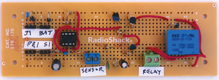 |
| PHOTO 1. |
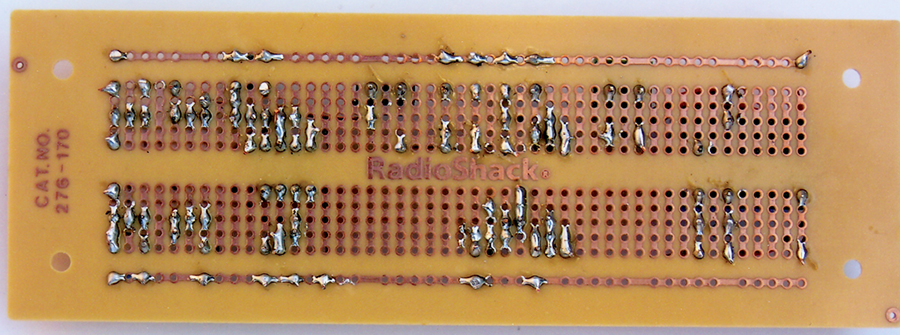 |
| PHOTO 2. |
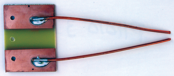 |
| PHOTO 3. |
Photo 1 shows the top side of the PCB (printed circuit board) and Photo 2 shows the reverse side of the PCB. The Parts List shows the component references. Be sure to use an eight-pin socket for U1. Install the parts on the perfboard. Transistor pinouts are shown in Figure 2. Attach 8” of red wire to the TIP terminal of J1, and 8“ of black wire to the RING terminal of J1. Then connect two 8” white wires to switch S1. Also connect a 12” red wire to the + terminal of the 12V battery and another 12” black wire to the – terminal of the battery. These wire colors are shown on the schematic in Figure 1.
The connections can be made by soldering the wires directly to the PCB, or they can be made using a female crimp housing connector mated to a .100” male header soldered to the PCB. Next, construct the probe assembly. Start with a 1.5“ by 2” piece of single sided, copper clad PCB. Put 3/4” pieces of tape on both sides and then etch. After etching, there should be copper foil as shown in Photo 3. (the probe assembly). Drill the three holes as indicated in the photo. Take two 4” lengths of 12 Ga wire and solder to the PCB. It may be necessary to use a 100 watt soldering iron to do this. Bend the wire at an angle such that they are separated by 1/8” at the tips. Next, make the cable that goes from TB1 to the probe assembly as follows. Cut two lengths of wire long enough to reach the case containing the circuit board from the probe assembly. Once these wires are cut, twist them together with a variable speed drill until they have about eight turns per inch. Then, strip about 1/2” of insulation from the end of each wire and tin.
One end of the twisted pair has ring tongue connectors soldered to them. These connectors are mounted to the probe assembly with two 4-40 1/4” long screws and two 4-40 nuts. The other end of the twisted pair is connected to terminals P1 and P2 of TB1 on the circuit board.
Testing and Assembly
Connect the unit to the 12V wall transformer. Then check the voltage between U1 pin 8 and U1 pin 1. The meter should read between 12 VDC and 18 VDC. If this reading is zero, check for proper installation of D1 and J1. When the voltage checks out, install U1 in its socket. Verify that the wires from the probe assembly are connected to P1 and P2. Then place the probe tips into water. The piezo alarm should sound. If the piezo is silent, flip the switch S1. If the alarm is still silent, check the installation of Q1, Q2, and Q3.
Once the alarm is working properly, mount the circuit board, J1, S1, and PZ1 in an appropriately sized case. Orient the switch S1 so that the piezo alarm is enabled when S1 is in the 12:00 position. Drill holes in the case to route the wires from TB1, TB2, PZ1, and the lantern battery. Also drill a hole to mount J1.
Use
Verify that the probe wires are connected to TB1. The TB2 terminal block is connected in series with the pump motor and the power source for the pump motor. The relay contact rating is 10A at 120 VAC. Once all of the necessary connections have been made, attach the lid to the case. When mounting the water detection alarm, care must be taken to install the unit, as well as the wall transformer in a place high above the expected flood level. The probe assembly should be placed such that the probe tips are exposed to water when flooding occurs. A 3/16” mounting hole on the probe assembly makes it easy to install. NV
PARTS LIST
|
| PART |
DESCRIPTION |
PART NO. |
SUPPLIER |
| U1 |
LM555CN |
LM555CNNS-ND |
|
| R1, R5, R6 |
10K 5% 1/4W |
10KQBK-ND |
|
| R1 |
1K 5% 1/4W |
1KQBK-ND |
|
| R2 |
470K 5% 1/4W |
470KQBK-ND |
|
| R4 |
1M 5% 1/4W |
1MQBK-ND |
|
| C1, C2 |
100 nF |
478-3187-ND |
|
| C3 |
10 nF |
478-2462-ND |
|
| C4, C5 |
22 µF 35V radial electrolytic |
P1188-ND |
|
| Q1 |
2N3904 |
2N3904FS-ND |
|
| Q2, Q3 |
2N3906 |
2N3906FS-ND |
|
| D1, D2, D4 |
1N4002 |
578-1360-1-ND |
|
| K1 |
10A SPST relay |
275-248A |
RS |
| J1 |
1/8” phone jack |
274-249 |
RS |
| PZ1 |
Piezo buzzer |
273-057 |
RS |
| TB1, TB2 |
PCB terminals |
276-1388 |
RS |
| S1 |
SPST toggle switch |
275-624 |
RS |
| Case |
|
270-1805 |
RS |
| Eight Pin Socket |
|
ED3308-ND |
|
| Terminals |
Ring tongue connector |
64-3032 |
RS |
| Four Standoffs |
4/40 1/2” Nylon standoffs |
1902CK-ND |
|
| Ten Screws |
4/40 1/4” screws |
Varies |
HWS |
| Two Screws |
4/40 3/8” screws |
Varies |
HWS |
| Four 4/40 nuts |
|
Varies |
HWS |
| Hookup Wire |
|
Varies |
HWS |
| Wall Xfmr |
12 VDC 200 mA transformer |
Varies |
|
| All part numbers are DigiKey except for RS part numbers (RadioShack) and HWS (your local hardware store). |